Journal of Applied Science and Engineering, Vol. 15, No. 2, pp. 187-196 (2012)
187
A Real-Time Object Recognition System Using Adaptive Resolution Method for Humanoid Robot Vision Development Chih-Hsien Hsia1*, Wei-Hsuan Chang2 and Jen-Shiun Chiang2 1
Department of Electrical Engineering, National Taiwan University of Science and Technology, Taipei, Taiwan, R.O.C. 2 Department of Electrical Engineering, Tamkang University, Tamsui, Taiwan 251, R.O.C.
Abstract The research of autonomous robots is one of the most important challenges in recent years. Among the numerous robot researches, the humanoid robot soccer competition is very popular. The robot soccer players rely on their vision systems very intensively when they are in the unpredictable and dynamic environments. This work proposes a simple and real-time object recognition system for the RoboCup soccer humanoid league rules of the 2009 competition. This vision system can help the robot to collect various environment information as the terminal data to complete the functions of robot localization, robot tactic, barrier avoiding, etc. It can reduce the computing complexity by using our proposed approach, adaptive resolution method (ARM), to recognize the critical objects in the contest field by object features which can be obtained easily. The experimental results indicate that the proposed approach can increase the real-time and accurate recognition efficiency. Key Words: Robot, RoboCup, Adaptive Resolution Method, Object Recognition, Real-Time
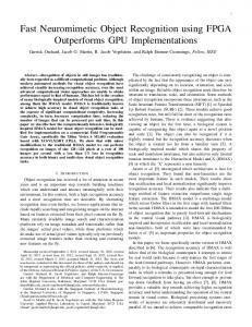
1. Introduction RoboCup [1] is an international joint project to stimulate researches in the field of artificial intelligence, robotics, and related fields. According the rules of RoboCup 2009 in the humanoid league of kid size, the competitions take place on a rectangular field of 600´400 cm2 area, which contains two goals and two landmark poles. A goal is placed in the middle of each goal line. One of the goals is colored in yellow and the other is colored in blue. The goal for the kid size field has 90 cm of height for the crossbar, 40 cm of height for the goal wall, 150 cm of width for the goal wall, and 50cm of depth for the goal wall as shown in Figure 1. The two landmark poles are placed in each side of the two intersection points between the touch line and the middle *Corresponding author. E-mail:
[email protected]
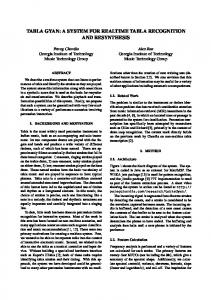
field line. The landmark pole is a cylinder and has a diameter of 20 cm. It consists of three segments of 20 cm height, stacked each other. The lowest and the highest segments have the same color as the goal of its left side, as shown in Figure 2. The ball is the standard size orange tennis ball. All of the above objects are the most critical characteristics in the field, and they are also the key features which we have to pay attention to. The functions of humanoid robot vision system include image capturing, image analyses, and digital image processing by using visual sensors. For digital image processing, it is to transform the image into the analyzable digital pattern by digital signal processing. We can further use image analysis techniques to describe and recognize the image content for the robot vision. The robot vision system can use the environment information captured in front of the robot to recognize the image by means of the technique of human vision system. An
188
Chih-Hsien Hsia et al.
The rest of this paper is organized as follows. Section 2 presents the related background such as the general color based object recognition method, low resolution method, and encountered problems. Section 3 describes the proposed approach, ARM. The experimental results are shown in section 4. Finally, the conclusions are outlined in section 5.
2. Background Figure 1. The goal information [2].
Figure 2. The landmark information [2].
object recognition algorithm is thus proposed to the humanoid robot soccer competition. Generally speaking, object recognition uses object features to extract the object out of the picture frame, and thus shape [3,4], contour [5-7], color [8,9], texture, and sizes of object features are commonly used. It is important to extract the information in real-time because the moving ball is one of the most critical object in the contest field. The complex feature such as contour is not suited to recognize in our application. The objects don’t have the obvious texture which is not suited to use in the contest field. However the object color is distinctive in the contest field, we mainly choose the color information to determine the critical objects. Although this approach is simple, the real-time efficiency is still low. Because there is a lot of information to be processed in every frame for real-time consideration, Sugandi et al. [10] proposed a low resolution method to reduce the information. It can speed up the processing time, but the low resolution results in a shorter recognizable distance and it may increase the false recognition rate. In order to improve the mentioned drawbacks, we propose a new approach, adaptive resolution method (ARM), to reduce the computation complexity and increase the accuracy rate.
2.1 Color Based Object Recognition Method An efficient vision system plays an important role for the humanoid robot soccer players. Many robot vision modules have provided some basic color information, and it can extract the object by selecting the color threshold. The RGB color model comes from the three additive primary colors, red, green, and blue. The main purpose of the RGB color model [11] is for the sensing, representation, and display of images in electronic systems, such as televisions and computers, and it is the basic image information format. The X, Y, and Z axes represent the red, green, and blue color components respectively, and it can describe all colors by different proportion combinations. Because the RGB color model is not explicit, it can be easily influenced by the light illumination and make people select error threshold values. An HSV (HSV stands for hue, saturation, and value) color model relates the representations of pixels in the RGB color space, which attempts to describe perceptual color relationships more accurately than RGB. Because the HSV color model describes the color and brightness component respectively, the HSV color model is not easily influenced by the light illumination. The HSV color model is therefore extensively used in the fields of color recognition. We can directly make use of H and S to describe a color range of high environmental tolerance. It can help us to obtain the foreground objects mask, M(x,y), by the threshold value selection as shown in (1). (1) where TH1, TH2, and TS are the thresholds of hue and threshold of saturation by manual setting. The foreground object mask usually accompanies with the noise, and we can remove the noise by the simple morpho-
A Real-Time Object Recognition System Using Adaptive Resolution Method for Humanoid Robot Vision Development
logical methods, such as dilation, erosion, opening, and closing. It needs to separate the objects by labeling when many objects with the same colors are existed in the frame. By using the above-mentioned procedure, the objects can be extracted. Although this method is simple, it is only suitable for low frame rate sequences. For a high resolution or noisy sequence, this approach may need very high computation complexity.
2.2 Low Resolution Method To overcome the above-mentioned problems, several approaches of low resolution method were proposed [10,12]. Several low resolution methods, such as the approach of applying 2-D discrete wavelet transform (DWT) and the using of 2´2 average filter (AF), were discussed. Cheng et al. [12] applied the 2-D DWT for detecting and tracking moving objects and only the LL3band image is used for detecting motion of the moving object (It is suggested that the LL3-band is a good candidate for noise elimination (the user can choose a suited decomposition level according to the requirement, and actually there is no need to do the reconstruction for these applications). Because noises are preserved in high-frequency, it can reduce computing cost for postprocessing by using the LL3-band image. This method can be used for coping with noise or fake motion effectively, however the conventional DWT scheme has the disadvantages of complicated calculation when an original image is decomposed into the LL-band image. Moreover if it uses an LL3-band image to deal with the fake motion, it may cause incomplete moving object detecting regions. Sugandi et al. [10] proposed a simple method by using the low resolution concept to deal with the fake motion such as moving leaves of trees. The low resolution image is generated by replacing each pixel value of an original image with the average value of its four neighbor pixels and itself. It also provides a flexible multi-resolution image like the DWT. Nevertheless, the low resolution images generated by using the 2´2 AF method are more blurred than that by using the DWT method. It may reduce the preciseness of post-processing (such as object detection, tracking, and object identification). In order to detect and track the moving object more accurately, we propose a new approach, adaptive resolu-
189
tion method (ARM), which is based on the 2-D integer symmetric mask-based discrete wavelet transform (SMDWT) [13]. It does not only retain the features of the flexibilities for multi-resolution, but also does not cause high computing cost when using it for finding different subband images. In addition, it preserves more image quality of the low resolution image than that of the average filter approach [10]. 2.2.1 Symmetric Mask-Based Discrete Wavelet Transform (SMDWT) SMDWT has many advanced features such as short critical path, high speed operation, regular signal coding, and independent subband processing [13]. The derivation coefficient of the 2-D SMDWT is based on the 2-D 5/3 integer lifting-based DWT. For computation speed and simplicity considerations, four-masks, 3´3, 5´3, 3´5, and 5´5, are used to perform spatial filtering tasks. Moreover, the four-subband processing can be further optimized to speed up and reduce the temporal memory of the DWT coefficients. The four-matrix processors consist of four-mask filters, and each filter is derived from one 2-D DWT of 5/3 integer lifting-based coefficients. In the ARM approach, we can select only the LL-band mask of SMDWT. The matrix coefficients of the LL-mask are shown in Figure 3 [13].
3. The Proposed Method 3.1 Adaptive Resolution Method (ARM) ARM takes advantage of the information obtained from the image to know the area of the ball and chooses the most suitable resolution. The operation flow chart is shown in Figure 4. After HSV color transformation, ARM chooses the most proper resolution by the situation at this moment in time. The high resolution approach brings a longer recognizable distance but with a slower
Figure 3. The subband masks coefficients of the LL-mask.
190
Chih-Hsien Hsia et al.
Figure 4. The flow chart of ARM.
running speed. On the other hand, the low resolution approach brings a lower recognizable distance but with a faster running speed. When we got the area information of the ball from the image last time, we could convert it as the “sel” signal through the adaptive selector to choose the appropriate resolution. The “sel” condition is shown in (2):
(2)
In (2), Athd1 and Athd2 are the threshold values for the area of ball. The relationship between the resolution and the distance of the ball is described in Table 1. According to Table 1, we can conclude that Athd1 and Athd2 are set to 54 and 413, respectively. The threshold selection is performed for each different resolution of working environment. The threshold value is used to produce the recognizable distance. If the ball disappears in the frame, the frame will change into the original size to have a higher probability to find out the ball. Since the sizes of other critical objects (such as goal and landmark) in the field are larger than the ball, they can be recognized easily.
3.2 Sample Object Recognition Method According to the above-mentioned color segmenta-
tion method, it can fast and easily extract the orange ball in the field, but it is not enough to recognize the goals and landmarks. The colors of the goals and landmarks are yellow and blue, and by color segmentation the extraction of goals and landmarks may not be correct. Therefore we have to use more features and information to extract them. Since the contest field is not complicated, a simple recognition method can be used to reduce the computation complexity. The landmark is a cylinder with three colors. Let us look at one of the landmark with the upper and bottom layers in yellow, and the center layer in blue; this one is defined as the YBY-landmark. The diagram is shown in Figure 5. The color combinations of the other one are in contrast of the previous one, and the landmark is defined as the BYB-landmark. The labels of the YBY-landmark can be calculated by (3). The BYB landmark is in the same manner as the YBYlandmark.
Figure 5. The diagram of the landmark.
Table 1. The relationship between the resolution and the distance of the ball Resolution
Level of DWT
Recognizable max distance of ball
*Area of ball
320 ´ 240 160 ´ 120 80 ´ 60
0 (original) 1 2
404.6 cm 322.8 cm 121.3 cm
18 pixels 54 pixels 413 pixels0
* The area means the pixel number in the original resolution.
A Real-Time Object Recognition System Using Adaptive Resolution Method for Humanoid Robot Vision Development
(3) According to the above-mentioned labeling procedure, we labeled all of the yellow and blue components in the frame and assigned the numbers to those components. Where LYi is defined the pixels of the i-th yellow component (Y), ymin and ymax the minimum value and the maximum value for the object i at y direction respectively, xc and yc the center point of the object at the horizontal and vertical direction respectively. The vertical bias value bY is set as 15. The landmark is composed of two same color objects in the vertical line, and the center is in different color. If it can find an object with this feature, the system can treat this object as the landmark and outputs the frame coordinate data. The result of landmark recognition is shown in Figure 6. Eq. (4) is used to define the label of the ball:
191
where LmB is the pixel of the m-th blue component in a picture frame. Since the blue goal is composed of the blue object, it is not a part of the YBY-landmark and BYB-landmark. The size of the goal in the field is the largest object, and therefore we set the parameter g as 50. The result of goal recognition is shown in Figure 8. The yellow goal is in the same manner as the blue goal.
3.3 Coordinate Transformation Because our proposed approach, ARM is using the different resolutions in the object recognition, we transform the coordinate into the original resolution by levelbased of DWT when the object information is outputted. The transform equation is defined in (6). (6) where O is the original image, LLn is the LL-band iamge after transformation, and n is the transformation level.
4. Experimental Results (4)
where LsO is the pixel of the s-th orange component in a frame. Since the ball is very small in the picture frame, in order to avoid noise, the ball is treated as the maximum orange object and with a shape ratio of height to width approximately equal to 1. Here a1 and a2 are set to 0.8 and 1.2, respectively. The result of ball recognition is shown in Figure 7. The goal recognition is defined in (5).
(5)
Figure 6. The result of landmark recognition.
In this work, the environment information is extracted by the Logitech QuickCam Ultra Vision. The image resolution is 320´240, and the frame rate is 30 fps (frame per second). For the simulation computer, the CPU is Intel Core 2 Duo CPU 2.1GHz, and the development tool is Borland C++ Builder 6.0.
Figure 7. The result of ball recognition.
Figure 8. The result of goal recognition.
192
Chih-Hsien Hsia et al.
This work is dedicated to the RoboCup soccer humanoid league rules of the 2009 competition. In order to prove the robustness of the proposed approach, many scenes of various situations are simulated to verify the high recognition accuracy rate and fast processing time. For the analyses of recognition accuracy rate, it is classified as a correct recognition if the critical object is labeled completely and named correctly such as the objects of Goal [B] and Ball shown in Figure 9(a). On the other hand there are two categories for false recognition, “false positive” and “false negative”. “False positive” means that the system recognizes the irrelevant object as the critical object, such as the Goal [Y] shown in Figure 9(b). “False negative” means the system cannot label or name the critical object, such as those balls shown in Figures 9(c) and (d).
4.1 Low Resolution Analysis Several low resolution methods, such as down-sampling (DS), AF, and SMDWT, were implemented and simulated in this experiment and the noise removing capabilities with these methods were analyzed. The input frame resolution is 320´240, and the resolution turns to be 160´120 after the low resolution processing. The noise numbers under different low resolution methods were counted. The contents of the simulated scene are obtained by turning the camera to left to see the YBYlandmark and keeping turning until the YBY-landmark disappeared from the camera scope. In this situation the background of the scene produces noise very easily. The
hue threshold values of the orange, yellow, and blue colors are set as 35~45, 70~80, and 183~193, respectively, and the saturation threshold of the orange, yellow, and blue colors values are all set as 70. The experimental results under different low resolution methods, DS, AF, and SMDWT, are listed in Table 2. According to Table 2, the DS approach has the worst noise removing capability; the 2´2 AF approach also has a bad noise removing capability for big noise block even though this method can make the image smoother. On the other hand, the SMDWT approach (using LL-mask only) has a better noise removing capability than the other methods, and it can retain the information of low-frequency component and remove the noise of high-frequency component in the image. In order to improve the noise removing capability of the whole system, we added the opening operator (OP) of mathematical morphology after labeling. The results after adding the opening operator are shown in Table 3. Compared with the results of Table 2, the noise numbers are reduced significantly after adding the opening operator, and it can reduce the unnecessary computation. The SMDWT approach has the best performance and the frame rate can be as high as 30 fps. Therefore this work adopts the SMDWT approach as the low resolution method.
4.2 Adaptive Resolution Method (ARM) Analyses In this experiment, we try to verify that ARM does not only retain high recognition accuracy rate, but also
Figure 9. The determination of recognition accuracy.
Table 2. The noise counts under different low resolution methods Method DS AF SMDWT
Total frame
Total noise number
*Average noise number
Average frame rate
153
4,133 3,191 2,670
27.01 20.86 17.45
42.24 fps 41.03 fps 38.13 fps
* Average noise number = (Total noise number) / (Total frame).
A Real-Time Object Recognition System Using Adaptive Resolution Method for Humanoid Robot Vision Development
193
Table 3. The noise counts under different low resolution methods with opening operator Method
Total frame
Total noise number
Average noise number
Average frame rate
153
408 334 60
2.67 2.18 0.39
38.01 fps 37.73 fps 30.95 fps
DS + OP AF + OP SMDWT + OP
can raise the system processing efficiency. The hue threshold values of the orange, yellow, and blue colors are set as 35~45, 70~80, and 183~193, respectively. The saturation threshold values of the orange, yellow, and blue colors are all set as 70. To verify the ARM approach, the camera is set in the center of the contest field. The scene tries to simulate that the robot kicks ball into the goal and the vision system will track the ball. The results under resolutions of 320´240, 160´120, 80´60, and ARM are shown in Table 4. According to Table 4, although the 320´240 resolution has a high accuracy rate, the processing speed is slow. The 80´60 resolution has the highest processing speed, but it has the lowest accuracy rate. By this approach, it gets high accuracy rate only when the object is close to the camera. On the other hand, the proposed ARM approach does not only have a high accuracy rate, but also keeps high processing speed. ARM uses the 80´60 resolution when the level is equal to 2 and uses the 160´80 resolution when the scale level is equal to 1. As the scale level is equal to 0, ARM selects the original input frame size (320´240).
4.3 The Critical Objects Recognition Analysis In this experiment, several scenes were simulated to improve the robustness of feature recognition approaches proposed in this work.
4.3.1 Landmark Recognition Analysis According to (3), the landmark is composed of two same color objects in the vertical line, and the bias value b is the key point to make sure whether this block is a landmark or not. A small bias value b will cause the missing recognition, however a large b may recognize an irrelevant block as a landmark. In this experiment, different values of b were set to test the effects. The scene is used for simulating that the camera captures a slantwise landmark when the robot is walking. The hue threshold values of the orange, yellow, and blue colors are set as 35~45, 65~75, and 175~185, respectively. The saturation threshold values of the orange, yellow, and blue colors are all set as 60. The results under values of b equal to 5, 10, 15, and 20. The experiment data of landmark recognition is shown in Table 5. According to this table, we can have a higher recognition accuracy rate when b is greater than 15. Generally speaking, the vibration of robot walking is not more intense than the simulation, and therefore b is set as 15 in this work. It will increase the chance of false recognition as a larger b is used. 4.3.2 Goal Recognition Analysis The goal is the largest critical object in the field, and hence the camera always captures the incomplete goal in
Table 4. The experimental results of the accuracy rate and average FPS under different resolutions and ARM Resolution
Total frame
320´240 160´120 80´60 ARM
Object frame
False positive
False negative
138
0 0 0 0
6 52 109 7
138
Accuracy rate Average frame rate 95.65% 62.32% 21.01% 94.93%
16.93 fps 31.46 fps 59.84 fps 21.17 fps
Table 5. The experimental results under different values of b b 5 10 15 20
Total frame
664
Object frame
Correct recognition
Accuracy rate
Average frame rate
664
304 545 637 631
45.78% 82.08% 95.93% 95.03%
20.02 fps 20.07 fps 20.15 fps 20.18 fps
194
Chih-Hsien Hsia et al.
the frame when the robot is walking in the field. It causes a false recognition easily by using the feature of the shape ratio to recognize the goal. We improve this drawback by using the proposed method in section 3.2 and the experimental results are shown here. The camera is set in the center of the contest field. The scene tries to simulate that the robot raises its head to see the goal and turns right to see the YBY-landmark and then turns left to see the BYB-landmark. The hue threshold values of the orange, yellow, and blue colors are set as 35~45, 70~80, and 183~193, respectively. The saturation threshold values of the orange, yellow, and blue colors are all set as 60. The results are listed in Table 6. According to the result, the system can make the correct recognition of goal even though the goal is occluded.
most influence to the result of the color-based recognition method proposed in this work. Before the robot soccer competition we usually have one day to prepare for the contest, and therefore we can regulate the threshold values easily by the graph interface according to the luminance of the field. The results under different luminance are shown in Table 8. The system cannot only recognize the critical objects under different luminance, but it can also accommodate the light changing suddenly. This experiment simulates that the robot recognizes the BYB-landmark and ball in the field under the light changing suddenly. The hue threshold values of the orange, yellow, and blue colors are set as 33~43, 67~77, and 175~185, respectively. The saturation threshold values of the orange, yellow, and blue colors are all set as 50. The results are listed in Table 9. According to the result, the proposed method has a good performance about environmental tolerance.
4.3.3 Ball Recognition Analysis For the ball recognition, the system determines the orange block which has the maximum pixels as a ball for preventing the influence of noise. In this experiment, two balls are used in the scene. One ball is static in the field, and the other one moves into the frame and then moves away from the camera. The hue threshold values of the orange, yellow, and blue colors are set as 35~45, 70~80, and 183~193, respectively. The saturation threshold values of the orange, yellow, and blue colors are all set as 60. The result is shown in Table 7.
4.5 Synthetic Analyses In this experiment, several scenes were simulated to compare the recognition accuracy rate and processing time between the 320´240 resolution and ARM. Scene 1: the ball is approach it to the camera slowly. Scene 2: the robot is approaching the ball after shooting the ball to the goal. Scene 3: the robot finds the ball and then tries to get approaching and kick it. Scene 4: the camera captures a blurred image when the head motor of the robot is rotating very fast. Scene 5: the robot localizes itself by see-
4.4 Environmental Tolerance Analysis The color deviation by luminance variation has the Table 6. The experiment data of goal recognition condition Goal Recognition
Total frame 328
Object frame False positive False negative Accuracy rate Average frame rate 297
0
7
97. 64%
21.98 fps
Table 7. The experiment data of ball recognition Condition Ball Recognition Ball Occlusion
Total frame
Object frame
274 289
274 289
False positive False negative Accuracy rate Average frame rate 0 3
0 0
99.99% 98.96%
30.93 fps 20.69 fps
Table 8. The threshold values used under different luminance Luminance
Hue_O
Sat_O
Hue_Y
Sat_Y
Hue_B
Sat_B
016 lux 178 lux 400 lux 596 lux 893 lux
03~13 13~23 17~27 17~27 23~33
10 60 50 50 50
118~128 119~129 61~71 57~67 57~67
50 60 50 50 45
220~230 205~215 190~200 180~190 180~190
96 96 50 50 50
A Real-Time Object Recognition System Using Adaptive Resolution Method for Humanoid Robot Vision Development
195
Table 9. The experiment data of light influence Condition
Total frame
Object frame
False positive
False negative
1,219
1,219
0
0
Light Influence
Accuracy rate Average frame rate 99.99%
31.14 fps
cessing, but also achieves high accuracy and efficiency with the functions of object recognition and tracking. It has a high accuracy rate of more than 93% on average and the average frame rate can reach 32 fps in indoor. Future works on this topic include the following: 1. The techniques used are fairly basic, relaying only on a set of thresholds on the HSV color space, followed by connected components labeling (CCL). In this work, we utilize the region-based tracking algorithm to track the moving object motion. Labeling is useful when the moving objects in the scene. In this paper, we are describing a convention approach for CCL. Modern approaches have a speed up on the solution they refer to [15]. 2. In this work, the threshold values are trying in the soccer humanoid league rules of RoboCup 2009 competition. Because, the lighting conditions depend on the actual competition site. Lighting temperature may differ significantly from previous years. The field is illuminated presuming a sufficient bright and constant lighting on the field. Thus, the optimal threshold parameters using fixed coefficients in experiment (Now day, user usually have abundant time to set up parameter before the game). In future work, Instead of manually changing thresholds for each scenario, it might be better to learn these thresholds automatically for robot vision. Learning process will provide optimized general thresholds for all scenarios.
ing the landmarks. The hue threshold values of the orange, yellow, and blue colors are set as 35~45, 70~80, and 185~190, respectively. The saturation threshold values of the orange, yellow, and blue colors are all set as 50. The experiment data of these scenes are shown in Table 10. According to the simulation results, our proposed method accommodates many kinds of scenes. It has the accuracy rate of more than 93% on average and the average frame rate can reach 32 fps. It does not only maintain the high recognition accuracy rate for the high resolution frames, but also increases the average frame rate for about 11 fps compared to the conventional high resolution approach. Furthermore, all of the experimental result videos mentioned in this section are appended in [14].
5. Summary An outstanding humanoid robot soccer player must have a powerful object recognition system to fulfill the functions of robot localization, robot tactic, and barrier avoiding. In this paper we propose an HSV color based object segmentation method to accomplish the object recognition. The object recognition approach uses the proposed adaptive resolution method (ARM) and sample object recognition method, and it can recognize objects more robustly. The experimental results indicate that the proposed method is not only simple and real-time pro-
Table 10. The experimental results of several kinds of scene simulation Scene 1 2 3 4 5 Total
Resolution 320´240 ARM 320´240 ARM 320´240 ARM 320´240 ARM 320´240 ARM 320´240 ARM
Total frame Object frame False positive False negative Accuracy rate Average frame rate 165
165
409
409
919
919
679
627
1,114
1,114
3,286
3,234
1 0 27 11 16 1 3 2 12 4 59 18
5 4 1 2 15 28 83 88 60 74 164 196
96.36% 97.58% 93.15% 96.82% 96.63% 96.84% 86.28% 85.65% 93.54% 93.00% 93.10% 93.38%
20.49 fps 23.31 fps 21.36 fps 29.88 fps 19.75 fps 28.48 fps 19.29 fps 27.31 fps 22.38 fps 40.58 fps 20.78 fps 32.25 fps
196
Chih-Hsien Hsia et al.
Acknowledgement This work was supported by the National Science Council of Taiwan, R.O.C. under grant number NSC 98-2218-E-032-003.
References [1] Kitano, H., Asada, M., Kuniyoshi, Y., Noda, I. and Osawa, E., “Robocup: The Robot World Cup Initiative,” IJCAI-95 Workshop on Entertainment and AI/ ALife, pp. 19-24 (1995). [2] RoboCup Soccer Humanoid League Rules and Setup for the 2009 competition, http://www.robocup2009. org/153-0-rules. [3] Chaumette, F., “Visual Servoing Using Image Features Defined on Geometrical Primitives,” IEEE Conference on Decision and Control (1994). [4] Jean, J.-H. and Wu, R.-Y., “Adaptive Visual Tracking of Moving Objects Modeled with Unknown Parameterized Shape Contour,” IEEE International Conference on Networking, Sensing and Control (2004). [5] Sun, S. J., Haynor, D. R. and Kim, Y. M., “Semiautomatic Video Object Segmentation Using V Snakes,” IEEE Transactions on Circuits System Video Technology, Vol. 13, pp. 75-82 (2003). [6] Kass, M., Witkin, A. and Terzopoulos, D., “Snakes: Active Contour Models,” International Journal of Computer Vision, Vol. 1, pp. 321-331 (1988). [7] Canny, J., “A Computational Approach to Edge Detection,” IEEE Transactions on Pattern Analysis and Machine Intelligence, Vol. 8, pp. 679-698 (1986). [8] Herodotou N., Plataniotis K. N. and Venetsanopoulos
A. N., “A Color Segmentation Scheme for ObjectBased Video Coding,” IEEE Symposium on Advances in Digital Filtering and Signal Processing (1998). [9] Ikeda, O., “Segmentation of Faces in Video Footage Using HSV Color for Face Detection and Image Retrieval,” International Conference on Image Processing, Vol. 2, pp. III-913-III-916 (2003). [10] Sugandi, B., Kim, H., Tan, J. K. and Ishikawa, S., “Real Time Tracking and Identification of Moving Persons by Using a Camera in Outdoor Environment,” International Journal of Innovative Computing, Information and Control, Vol. 5, pp. 1179-1188 (2009). [11] Gonazlez, R. C. and Woods, R. E., Digital Image Processing (2nd Ed), Addison-Wesley (1992). [12] Cheng, F.-H. and Chen, Y.-L., “Real Time Multiple Objects Tracking and Identification Based on Discrete Wavelet Transform,” Pattern Recognition, Vol. 39, pp. 1126-1139 (2006) [13] Hsia, C.-H., Guo, J.-M. and Chiang, J.-S., “Improved Low-Complexity Algorithm for 2-D Integer LiftingBased Discrete Wavelet Transform Using Symmetric Mask-Based Scheme,” IEEE Transactions on Circuits and Systems for Video Technology, Vol. 19, pp. 1-7 (2009). [14] The experiment result videos, http://www.youtube. com/view_play_list?p=3046A8B443052360. [15] Grana, C., Borghesani, D. and Cucchiara, R., “Optimized Block-Based Connected Components Labeling with Decision Trees,” IEEE Transactions on Image Processing, Vol. 19, pp. 1596-1609 (2010).
Manuscript Received: Apr. 25, 2011 Accepted: Sep. 26, 2011