Motion hands and fingers tracker and an AR marker. The system is capable of ... is used to determine the location of the Leap Motion sensor to help with consolidation of ..... is usually placed on the desk in front of the user. The Leap .... in Proceedings of the 18th ACM symposium on Virtual reality software and technology, pp ...
A real-time reconstructed 3D environment augmented with virtual objects rendered with correct occlusion Saad Khattak, Brent Cowan, Iuliia Chepurna, Andrew Hogue University of Ontario Institute of Technology Oshawa, ON - Canada {saad.khattak, brent.cowan, iuliia.chepurna, andrew.hogue}@uoit.ca
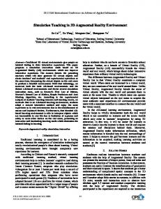
Fig. 1: Screenshots of the left view showing correct occlusion of the user’s hands and the virtual object (a 3D textured crate). The AR marker cannot be seen because it is directly behind the virtual object.
Abstract—In this work we present a novel framework for the real-time interaction with 3D models in augmented virtual reality. Our framework incorporates view-dependent stereoscopic rendering of the reconstructed environment together with user’s hands and a virtual object, and high-precision gesture recognition to manipulate it. Proposed setup consists of a Creative RGB-D camera, Oculus Rift VR head mounted display (HMD), Leap Motion hands and fingers tracker and an AR marker. The system is capable of augmenting the user’s hands in relation to their point of view (POV) using the depth sensor mounted on the HMD, and allows manipulation of the environment through the Leap Motion sensor. The AR marker is used to determine the location of the Leap Motion sensor to help with consolidation of transformations between the Oculus and the Leap Motion sensor. Combined with accurate information from the Oculus HMD, the system is able to track the user’s head and fingers, with 6-DOF, to provide a spatially accurate augmentation of the user’s virtual hands. Such an approach allows us to achieve high level of user immersion since the augmented objects occlude the user’s hands properly; something which is not possible with conventional AR. We hypothesize that users of our system will be able to perform better object manipulation tasks in this particular augmented VR setup as compared to virtual reality (VR) where user’s hands are
not visible, or if visible, always occlude virtual objects. Index Terms—depth sensor, Oculus Rift, Leap, augmented reality, hand tracking reconstruction, virtual reality
I. I NTRODUCTION For a user to successfully perform tasks in virtual reality environments (VREs), a certain level of immersion should be provided by the system [1], [2]. With the current advancements in the high resolution, realistic, stereoscopic 3D rendering and accurate tracking technologies, developers have been able to push the feeling of presence in virtual worlds further than ever before. High-fidelity stereoscopic rendering of 3D scenes has become possible with the introduction of affordable head mounted displays. One such display available to consumers is the Oculus Rift HMD. The emerging trend of employing natural user interfaces (NUIs) has lead to a shift from conventional interaction controllers, such as expensive data gloves and motion tracking setups towards low-cost highly accurate devices aimed to the mass consumer market. Sensors
similar to Microsoft Kinect are marketed to be low cost depth sensors that can be used to track users and reconstruct environments. Leap Motion controller is a small, high resolution, fast response hand and finger tracker. In this work we want to integrate the aforementioned components together to deliver an engaging and immersive user experience. The objective of proposed system is to provide an augmented virtuality (AV) interface for interaction with 3D models. Users interact with the system while seated at a table with the Leap Motion controller placed directly in front of them. The Leap Motion is capable of tracking hand and finger gestures, which allows for the manipulation of virtual objects without the need for a controller. The depth sensor is mounted on the HMD and is used to reconstruct not only the immediate surrounding environment but also the user’s hands which can then be rendered in the virtual environment using the Oculus Rift VR HMD. An augmented reality (AR) marker is placed near the Leap Motion controller at a known distance to ensure correct spatial positioning of the devices relative to the user’s point of view (POV) (Figure 3).
Fig. 3: Our setup includes the Leap Motion sensor, depth sensor and Oculus Rift HMD. The RGB-D sensor is mounted on the HMD. AR tags, shown in green, must always be visible to the RGB-D sensor. Users sit at approximately half an arms length from the Leap sensor. The Leap’s volume of interaction (blue) is displayed to the user in the HMD. Availability of the visual cues helps the user navigate within the VRE more efficiently. It has been shown that the selfembodiment of the user in a rendered scene by way of an avatar facilitates the perception of spatial characteristics of the virtual world [3]. The results of several studies indicated that users are able to judge distances more accurate with an avatar present in the virtual environment [3], [4]. A study using the rubber hand illusion has also shown that users are not able to accurately estimate the distance from their body to a specific point when exposed to a mock rubber hand instead of the direct vision of their real hand [4]. This paper is organized as follows. Related work is dis-
cussed in Section II. Details of the setup implementation and proposed solutions are presented in Section III. II. R ELATED W ORK Some research projects used Kinect in exergames where an instructor and their environment is replicated using the Kinect [5]. The information from the depth sensor is used to create a depth map, which, when used in conjunction with a standard RGB camera, can recreate a visualization of the environment that can be displayed in a 3D scene [6]. KinectFusion allows reconstruction of indoor scenes with a standard Kinect without any extra setup or calibration. The technique uses the depth measurements from the Kinect’s sensor to track the movement of the Kinect while reconstructing the environment using the iterative closest point (ICP) algorithm [7]. The 3D points provided by the Kinect are compared to the voxelized reconstruction to determine the Kinect’s new position and orientation. Once the sensors orientation is known, the points can be used to further refine the voxel representation. Compiling data from several frames captured from different angles allows KinectFusion to remove the noise that is inherent in Kinect’s depth samples. Kinect’s capabilities along with other hardware such as the Leap and Oculus Rift are also used in multiple other successful augmented reality projects [8], [9]. OmniKinect is a system that supports real-time volumetric data acquisition [10]. Up to twelve Kinects are rigidly mounted on a steel frame allowing objects to be viewed from several directions simultaneously. Objects within the viewing area may be voxelized in real-time which allows animating objects and people to be captured. The reconstructed objects and animations can be viewed from any angle using augmented reality. The accuracy and efficiency of OmniKinect was compared to KinectFusion revealing a small decrease in processing time and improved accuracy of the reconstruction [10]. Oculus Rift is a HMD developed by Oculus VR [11]. One of the defining features of the HMD is its high field of view (FOV) at 110 degrees (diagonal). The high FOV comes at the cost of distortion by the headset’s lenses which must be corrected in a post-processing step. The current version of the device has a relatively low resolution of 1280 × 800, with an effective resolution of 640 × 800 per eye. The newer version of the device has an increased resolution of 1920 × 1080 or 960 × 1080 per eye [11]. Leap Motion is an optical 3D sensor which gets the depth information from the environment based on the travel time of reflected infrared (IR) beams. It is designed to recognize and track hands, fingers and any object which can be treated as a pointer with high precision and speed with a reported accuracy of 0.2mm and 1.2mm for static and dynamic setups respectively [12]. Leap Motion, and other optical sensors, have limitations such as occlusion and overall sensor instability over time. There has been a number of successful projects using Leap Motion as a main or single controller. Some of the applications include: manipulation of 3D objects [13], point
clouds annotation [14], [15], control of a gripper robot [16], segmentation of volumetric medical data [17], facilitating collaboration on multi-touch tables for disabled users [18], therapy sessions with serious games [19], [20], modeling of the prosthesis socket [21] and even monitoring symptoms of amnestic mild cognitive impairment (MCI) for elderly people [22]. To the best of our knowledge, current work is the only one combining the following components: 3D scene reconstruction done by a single depth sensor, stereoscopic rendering with respect to user’s head orientation using Oculus Rift, free-hand spatial object manipulation with Leap Motion, and augmenting virtual reality with user’s hands extracted with the help of depth sensor. Here we briefly review the previous work sharing main components with our setup. One of the first fundamental studies combining most of the computer vision technologies conducted by Raskar et al. [23] was concerned with the prototype of the Office of the Future. Although breakthrough approaches were developed (e.g. rendering image on irregular surfaces with color and geometry compensation, unobtrusive capturing of 3D model of the room, real-time RGB data transmission for teleconferencing), rendering of the image from user’s point of view and usage of gestures were not addressed. Recent study by Corbett-Davies et. al. used AV for arachnophobia exposure treatment [24] and has presented very naturalistic interaction between virtual objects (spiders) and the real world. However, rendering was limited to a single regular display, and view didn’t change when user was moving around. Work proposed by Lu et.al. [25] aimed to provide a gesturebased interface for interaction with 3D models. The authors devised a relatively complex and expensive setup for head and fingers tracking consisting of data gloves, set of RGB cameras and ultrasonic sensor (in contrast, the work presented here makes use of Leap Motion for finger tracking), AR marker and Kinect. Immersion and interaction are crucial factors in the design and development of VR systems [26]. A wealth of prior work has been conducted in these areas. Clarke [27] produced a tabletop racing game using a depth-sensing camera. The main contribution of that work was the integration of the Kinect in an AR framework to provide the 3D information about the environment and to develop an environmentally aware AR application that would create a more immersive AR experience for the user. Another more closely related system is by Sabines et al. where immersive user experience was proposed with KinectFusion, Leap Motion and Oculus devices [28]. The proposed setup allowed tourists to visit cultural heritage sites in a realistic virtual setting. The authors found their system to provide a more immersive user experience than static setups. III. I MPLEMENTATION The setup of our framework is shown in Figure 3. The user is seated at the table wearing an Oculus Rift VR headset. The Leap Motion is placed in the center of the table in front of the
user so that their hands are in the sensor’s interaction volume. An RGB-D sensor (Creative Interactive Gesture Camera) is mounted on the HMD which allows the depth sensor to capture the user’s hands as well as the surrounding environment which includes the Leap Motion. An AR marker is placed at a known location near the Leap Motion controller. RGB data from the RGB-D sensor is used to track the AR marker allowing the system to calculate the world transformations of the augmented environment in relation to the Oculus headset and the Leap Motion sensor. We use the RGB-D sensor for several tasks: it calculates Leap’s position based on AR marker associated with it; it captures both static and dynamic parts of the scene – table top when the user is absent, and user’s hands if available in the frame. The RGB data from the sensor is used to track the AR marker, and Leap Motion – for monitoring movements of the hands. A rendered scene consists of the static scene (table), dynamic scene (user’s arms and hands), virtual room, spheres showing user’s fingertips, and a virtual 3D object to manipulate. The reconstructed environment is rendered in realtime by the Oculus Rift with respect to user’s head position and orientation. A. Creative RGB-D Sensor 1) Background: The depth sensor technology (also known as a RGB-D sensor) developed by PrimeSense can already be found in over 20 million households globally in the form of the Microsoft Kinect motion sensing input device for the Xbox 360, and Xbox One video game consoles [29]. The depth sensing capability of the Kinect has been combined with a human motion capturing algorithm to allow players to interact with games using full body gestures. The Kinect has generated a lot of interest from the research community due to its low cost when compared to stereo and time-of-flight (TOF) cameras [30]. Sensors similar to the Kinect contain an infrared laser that is split into multiple beams by way of a diffraction grating. A consistent pattern of dots called a speckle pattern is projected into the scene and captured by an infrared camera located next to the RGB camera. The speckle pattern is compared to a reference pattern which was captured at a known distance from the camera. The horizontal offset of each point in the scene is used to determine the distance at that point (or speckle) [31]. The space between points is filled based on the depth of the nearest point in order to complete the depth image. There are far more pixels in the 640 × 480 depth image than points in the speckle pattern which means that each depth point results in a group of several pixels. These groups of pixels overlap edges causing them to appear rough. Pixels near an edge may receive a depth value from a point that belongs to a different surface. In addition, the depth data returned by the points may be noisy, incorrect, or in some cases non-existent. A depth value of 0 is returned for points that could not be evaluated which means that no information is available for that portion of the map (holes). Reflections, transparent objects, and dark colored surfaces may cause holes in the depth map
or increase noise in the data [30]. Even under ideal conditions, noise is unavoidable causing depth values to change slightly from one frame to the next. This seemingly random noise is proportional to the squared distance between the depth sensor and the surface [31]. 2) Repairing the Depth Map: Due to the amount of noise and missing data, the depth maps often need to be repaired before they can be used. Filling holes in the depth image is generally accomplished by conducting a survey of neighboring pixels either spatially or temporally. In a static scene, depth values can be compiled over several frames of video. Averaging the non-zero depth values will fill many of the holes while removing most of the noise. For our implementation, we used the RGB-D data provided by the Creative sensor to render the user’s hands, so that the user is able to see their own hands in the virtual environment viewed using the Oculus Rift VR headset. The user’s hands will be moving throughout the experiment which excludes the use of temporal data for repairing the depth map. Our algorithm has been implemented using the GLSL shading language to repair each depth map before they are converted to a mesh and displayed to the user. A 7 × 7 kernel is used to compare the depth and color of the neighboring pixels to that of the center pixel. If the center pixel does not have depth data (a hole) than it is compared to its neighbors based on color only. Each neighbor is assigned a weight factor based on its similarity to the center pixel. The output depth is a weighted average of all of the neighbors. The algorithm removes surface noise and fills holes efficiently in one pass.
Fig. 4: The reconstructed environment using the RGB-D sensor. Once the environment has been reconstructed, its depth and color information is recorded. This information is then used instead of data from the sensor in cases where the user’s hand occludes the environment. 3) Rendering the RGB-D Data as a Mesh: A flat rectangular mesh is created from a 2D grid of vertexes measuring 640 × 480. Each vertex in the mesh corresponds to a pixel in
the depth map. A GLSL vertex shader is used to reposition each vertex based on the depth values provided in the map. The slope of each surface is also calculated by comparing the depth of neighboring vertexes so that surfaces that do not face the RGB-D sensor are removed (discarded in the fragment shader). If these surfaces were not removed, then objects in the foreground would have their outer edges extruded connecting them to objects in the background. An example of the mesh is presented in Figure 4.
Fig. 5: The reconstructed environment augmented with user’s hands. Notice that occlusion from the user’s hands does not produce holes in the environment. 4) Separating the Foreground from the Background: The static environment (table top and Leap motion controller) is captured and stored without the user present. During the study, the user (or at least their arms and hands) will be captured by the depth sensor at interactive rates. Only the closest surface to the sensor is captured for each pixel, hidden surfaces appear as holes in the rendered mesh. Without the static scene, the table would appear to have holes in it under the user’s hands. The mesh containing the user’s hands must be rendered with the table removed (see Figure 5), otherwise the two versions of the table would be rendered intersecting each other. Due to noise, the two surfaces would intersect randomly which may be visually distracting. The table is removed from the dynamically rendered scene by comparing the depth map with that of the static scene. All fragments in the dynamic scene with a similar depth to the static scene are discarded by the fragment shader. B. Oculus Rift head tracking The Oculus Rift [11] is an inexpensive HMD device with a high field of view and low latency targeted at consumers. The device returns accurate orientation of the user’s head but returns no positional data and is generally used in conjunction with other input devices, such as the mouse and keyboard.
1) Stereoscopic rendering: Stereoscopic rendering using a HMD is different than rendering to a stereoscopic display. The two main differences are: • •
the difference in distance between the eyes and display distortion compensation due to HMD’s lenses
Viewing a screen very close to the eyes limits the FOV of the user. The Oculus HMD avoids this limitation and provides a much higher FOV of 110 degrees (diagonal) by using lens magnification. This magnification results in pincushion distortion which must be corrected before the image is displayed on the device [11]. The distortion model performing this operation is as follows: (r, θ) 7→ (f (r)r, θ)
(1)
where r is the distance from lens center and θ is the angle to from a point in the image to center [11]. The scaling function given by the Oculus SDK is: f (r) = k0 + k1 r2 + k2 r4 + k3 r6
(2)
where k0 ...k3 control the distortion of a point in the image by manipulating its distance to center r [11]. The shader (modified from the original provided by Oculus SDK and converted to GLSL) for achieving this distortion with two fullscreen quads (as opposed to one full-screen quad split in two) can be seen towards end of this paper. An important note regarding the stereoscopic rendering is that although HMDs do not require off-axis or asymmetric projection (to define a convergence plane), the Rift still requires an offset or a skew in the z axis of the projection frustum which is very similar to normal stereoscopic projection. This is due to the distortion function and must be corrected by calculating the projection offset: P rojcof f = 4 ×
(Vc − Sh
Ld 2 )
(3)
where P rojcof f is the final projection offset, Vc is the horizontal view (screen) center, Ld is the lens separation distance (given by the SDK) and Sh is half the horizontal screen size [11]. Once P rojcof f is calculated, it can be substituted in the following transformation matrix and multiplied with the normal camera’s projection matrix for both the left and the right view cameras:
1 0 0 1 0 0 0 0
P rojcof f 0 1 0
0 0 0 1
C. Leap Motion Hand Tracking using AR markers The Leap Motion is a pocket-sized hand-tracking device that is usually placed on the desk in front of the user. The Leap Motion sensor is designed to track user’s hands and individual fingers (also any pointer-like objects) with the high precision and is capable of recognizing hand gestures in real-time. It was chosen in this project due to its lower cost and wider adoption by the Human Computer Interaction (HCI) and VR research community [16], [34]. 1) World Transformation of Leap Motion: The data from a Leap Motion device consists of finger positions and the direction vector of each finger. If the palm is detected then the orientation of the user’s hand is also returned. In this framework, the positions and direction vectors of each finger are displayed in the virtual environment with accurate spatial positioning relative to the user’s POV while wearing the Oculus HMD. The positions cannot be used directly as they must first be converted to world co-ordinates. In our case, the world origin is the RGB-D sensor. Our framework relies on OpenCV [32] and ArU co [33]. ArU co is a library for augmented reality applications which can detect predefined AR markers as well as an AR board. The board consists of several markers arranged in a grid pattern and can thus maintain a higher degree of accuracy especially in situations where the markers may be occluded or lit poorly. AR markers return transformation relative to the pose of the camera. Since the camera is mounted on the HMD, the transformation of the Leap Motion controller is calculated by offsetting the transformation given by the AR library by a known amount. The final transformation matrix of the Leap Motion controller is: � � RAR TAR + Lo (5) 0 1 where RAR is a 3 × 3 rotation matrix obtained from the AR tag, TAR is the transformation obtained from the AR tag and Lo is the offset of the Leap Motion controller relative to the AR tag. 2) Object Manipulation with Leap Motion: The Leap Motion SDK recognizes a variety of predefined gestures. In our experience, the gestures have a high degree of inaccuracy due to the relatively small interaction volume. Additionally, the gestures have to be performed carefully to avoid unintended movements as there is no visual or tactile feedback for the user to know that they are close to or have begun interacting with the device. IV. R ESULTS
(4)
Finally, the left and right view cameras are transformed in the right direction by ±Id /2 where Id is the interaxial (interpupillary) distance.
Figure 6 shows a user wearing the Oculus headset (D) with the Creative RGB-D sensor mounted on top (C). The Leap Motion sensor (A) is placed at a known position near the AR tag (B). The system is able to place the user’s POV and the Leap Motion sensor’s markers accurately using the transformations provided by the AR tags.
Fig. 6: A user interacting with our system using the Creative RGB-D sensor (C) while wearing the Oculus Rift VR headset (D). AR marker (B) is used to track the pose of the Leap Sensor (A) relative to the user’s head. Figure 7 shows a screenshot from the current version of our framework. The view is from Oculus HMD and appears distorted if viewed on a regular monitor. The user’s hands are encompassing a virtual object (crate) and the hands are correctly occluded by the virtual object. V. C ONCLUSION AND F UTURE W ORK In this paper we proposed a proof-of-concept of the novel VR-based setup for spatial data manipulation. To the best of our knowledge, this is the first prototype which integrates all of the well-known and widely used components of VR systems capable of providing a high level of immersion in a VR environment. We believe that the system can help a user to perform better while manipulating 3D objects, which can be particularly useful when analyzing multidimensional information. Our system is capable of rendering a 3D environment to the Oculus Rift HMD and augmenting the rendering with virtually reconstructed hands of the user by using the Creative RGB-D sensor. Accurate manipulation of 3D models is achieved by using the Leap Motion sensor. The system provides correct spatial positioning of the reconstructed environment relative to rendered virtual objects using an AR marker. In the near future we are planning to conduct a study that will quantitatively evaluate subjective user experience while using our system and objective performance when performing a set of predefined tasks. Our goal is to assess the overall usability and level of immersion delivered by the developed framework. We hypothesize that the presence of realistically rendered hands will significantly improve the overall experience of manipulating a virtual object as well as the success rate of performing specific tasks within the framework.
The experiment will be conducted as follows: • subjects will be given 3 to 5 minutes to familiarize themselves with controlling the objects using the Leap • they will be asked to perform a set of predefined tasks • the users will be evaluated based on how fast and accurately they perform the given tasks For this experiment, we will consider three different scenarios and will employ a between-subjects design to avoid any learning effects due to order of presentation. The order will be determined by a Latin Square. The three scenarios when interacting with the Leap Motion are: 1) no visual cues presented 2) only markers representing the fingertips shown 3) user’s hands, reconstructed using Kinect , shown In all three scenarios, the volume of interaction of the Leap Motion device will be shown as a transparent green object. After each test users will be asked to fill the Questionnaire for User Interaction Satisfaction (QUIS) [35] . In order to assess whether Leap Motion is causing user tiredness, subjects will also fill out the Borg Scale questionnaire [36]. The current system has some limitations that will be improved in future iterations. The camera frequently loses sight of the AR marker on the Oculus headset when the user’s head is rotated at extreme angle relative to the camera. Tracking can be improved by using a box with AR markers on each visible face. Currently, the framework uses exponential smoothing to reduce jitter produced by AR tracking. Future iterations of the system can use predictive tracking using SLAM which will also account for errors with AR markers. The single AR marker used in this paper can be replaced with an AR board which can provide higher accuracy and more robust tracking when the user’s hands occlude the markers. Implicit surfaces are more robust at repairing holes and thus improvements to the hole filling algorithm can be made by defining an implicit surface with the given depth values. Holes made by occlusion can also be repaired using existing implicit surface repair algorithms. VI. ACKNOWLEDGEMENTS We gratefully acknowledge the nancial support from NSERC for this research. R EFERENCES [1] D. A. Bowman and R. P. McMahan, “Virtual reality: how much immersion is enough?,” Computer, vol. 40, no. 7, pp. 36–43, 2007. [2] B. Laha and D. A. Bowman, “Identifying the benefits of immersion in virtual reality for volume data visualization,” in Immersive Visualization Revisited Workshop of the IEEE VR conference, 2012. [3] L. Phillips, B. Ries, M. Kaeding, and V. Interrante, “Avatar selfembodiment enhances distance perception accuracy in non-photorealistic immersive virtual environments,” in Virtual Reality Conference (VR), 2010 IEEE, pp. 115–1148, IEEE, 2010. [4] M. Kammers, F. de Vignemont, L. Verhagen, and H. C. Dijkerman, “The rubber hand illusion in action,” Neuropsychologia, vol. 47, no. 1, pp. 204–211, 2009. [5] K. Rector, C. L. Bennett, and J. A. Kientz, “Eyes-free yoga: an exergame using depth cameras for blind & low vision exercise,” in Proceedings of the 15th International ACM SIGACCESS Conference on Computers and Accessibility, p. 12, ACM, 2013.
Fig. 7: A screenshot of what the user in Figure 6 sees. There are two views for stereoscopic rendering. The views are distorted to compensate for the pincushion distortion due to Oculus’s lenses. The user’s hands are correctly occluded by the virtual object.
[6] S. Uzor and L. Baillie, “Investigating the long-term use of exergames in the home with elderly fallers,” in Proceedings of the 32nd annual ACM conference on Human factors in computing systems, pp. 2813–2822, ACM, 2014. [7] R. A. Newcombe, A. J. Davison, S. Izadi, P. Kohli, O. Hilliges, J. Shotton, D. Molyneaux, S. Hodges, D. Kim, and A. Fitzgibbon, “Kinectfusion: Real-time dense surface mapping and tracking,” in Mixed and augmented reality (ISMAR), 2011 10th IEEE international symposium on, pp. 127–136, IEEE, 2011. [8] A. Clark and T. Piumsomboon, “A realistic augmented reality racing game using a depth-sensing camera,” in Proceedings of the 10th International Conference on Virtual Reality Continuum and Its Applications in Industry, pp. 499–502, ACM, 2011. [9] K. Ikeuchi, T. Otsuka, A. Yoshii, M. Sakamoto, and T. Nakajima, “Kinecdrone: enhancing somatic sensation to fly in the sky with kinect and ar. drone,” in Proceedings of the 5th Augmented Human International Conference, p. 53, ACM, 2014. [10] B. Kainz, S. Hauswiesner, G. Reitmayr, M. Steinberger, R. Grasset, L. Gruber, E. Veas, D. Kalkofen, H. Seichter, and D. Schmalstieg, “Omnikinect: real-time dense volumetric data acquisition and applications.,” in Proceedings of the 18th ACM symposium on Virtual reality software and technology, pp. 25-32., ACM, 2012. [11] “Oculus rift website.” http://www.oculusvr.com/. Retrieved May 03, 2014. [12] F. Weichert, D. Bachmann, B. Rudak, and D. Fisseler, “Analysis of the accuracy and robustness of the leap motion controller,” Sensors (Basel, Switzerland), vol. 13, no. 5, p. 6380, 2013. [13] B. Fanini, “A 3d interface to explore and manipulate multi-scale virtual scenes using the leap motion controller,” in ACHI 2014, The Seventh International Conference on Advances in Computer-Human Interactions, pp. 258–263, 2014. [14] M. Cabral, A. Montes, O. Belloc, R. Ferraz, F. Teubl, F. Doreto, R. Lopes, and M. Zuffo, “Bi-manual gesture interaction for 3d cloud point selection and annotation using cots,” in 3D User Interfaces (3DUI), 2014 IEEE Symposium on, pp. 187–188, IEEE, 2014. [15] F. Bacim, M. Nabiyouni, and D. A. Bowman, “Slice-n-swipe: A free-
[16]
[17] [18] [19]
[20] [21]
[22]
[23]
[24] [25]
hand gesture user interface for 3d point cloud annotation,” in 3D User Interfaces (3DUI), 2014 IEEE Symposium on, pp. 185–186, IEEE, 2014. I. Zubrycki and G. Granosik, “Using integrated vision systems: Three gears and leap motion, to control a 3-finger dexterous gripper,” in Recent Advances in Automation, Robotics and Measuring Techniques, pp. 553– 564, Springer, 2014. B. Laha and D. A. Bowman, “Design of the bare-hand volume cracker for analysis of raw volumetric data,” in Immersive Volumetric Interaction (WIVI 2014), 2014 IEEE VR Workshop on, 2014. C. Creed, J. Sear, and R. Beale, “Using mid-air gestures to enhance collaborative experiences for disabled users on multi-touch tables,” R. Unnikrishnan, K. Moawad, and R. R. Bhavani, “A physiotherapy toolkit using video games and motion tracking technologies,” in Global Humanitarian Technology Conference: South Asia Satellite (GHTCSAS), 2013 IEEE, pp. 90–95, IEEE, 2013. J. Blaha and M. Gupta, “Diplopia: A virtual reality game designed to help amblyopics,” in Virtual Reality (VR), 2014 iEEE, pp. 163–164, IEEE, 2014. G. Colombo, G. Facoetti, C. Rizzi, and A. Vitali, “Socket virtual design based on low cost hand tracking and haptic devices,” in Proceedings of the 12th ACM SIGGRAPH International Conference on Virtual-Reality Continuum and Its Applications in Industry, pp. 63–70, ACM, 2013. I. Tarnanas, C. Mouzakidis, and W. Schlee, “Functional impairment in virtual-reality-daily-living-activities as a defining feature of amnestic mci: Cognitive and psychomotor correlates,” in Virtual Rehabilitation (ICVR), 2013 International Conference on, pp. 27–34, IEEE, 2013. R. Raskar, G. Welch, M. Cutts, A. Lake, L. Stesin, and H. Fuchs, “The office of the future: A unified approach to image-based modeling and spatially immersive displays,” in Proceedings of the 25th annual conference on Computer graphics and interactive techniques, pp. 179– 188, ACM, 1998. S. Corbett-Davies, A. Dunser, R. Green, and A. Clark, “An advanced interaction framework for augmented reality based exposure treatment,” in Virtual Reality (VR), 2013 IEEE, pp. 19–22, IEEE, 2013. G. Lu, L.-K. Shark, G. Hall, and U. Zeshan, “Immersive manipulation of virtual objects through glove-based hand gesture interaction,” Virtual Reality, vol. 16, no. 3, pp. 243–252, 2012.
[26] O. Grau, Virtual Art: From Illusion to Immersion (Leonardo Book Series). The MIT Press, 2004. [27] A. Clark and T. Piumsomboon, “A realistic augmented reality racing game using a depth-sensing camera,” in Proceedings of the 10th International Conference on Virtual Reality Continuum and Its Applications in Industry (VRCAI ’11), (Hong Kong, China), pp. 499–502, ACM, 2011. [28] S. Webel, M. Olbrich, T. Franke, and J. Keil, “Immersive experience of current and ancient reconstructed cultural attractions,” in Digital Heritage International Congress (DigitalHeritage), 2013, vol. 1, pp. 395– 398, Oct 2013. [29] “Primesense website.” http://www.primesense.com. Retrieved January 30, 2014. [30] J. Han, L. Shao, D. Xu, and J. Shotton, “Enhanced computer vision with microsoft kinect sensor: A review,” 2013. [31] K. Khoshelham and S. O. Elberink, “Accuracy and resolution of kinect depth data for indoor mapping applications,” Sensors, vol. 12, no. 2, pp. 1437–1454, 2012. [32] “Opencv website.” http://opencv.org/. Retrieved May 3, 2014. [33] “Aruco website.” http://www.uco.es/investiga/grupos/ava/node/26. Retrieved May 3, 2014. [34] J. Bolton, M. Lambert, D. Lirette, and B. Unsworth, “Paperdude: A virtual reality cycling exergame,” in CHI ’14 Extended Abstracts on Human Factors in Computing Systems, CHI EA ’14, (New York, NY, USA), pp. 475–478, ACM, 2014. [35] J. P. Chin, V. A. Diehl, and K. L. Norman, “Development of an instrument measuring user satisfaction of the human-computer interface,” in Proceedings of the SIGCHI conference on Human factors in computing systems, pp. 213–218, ACM, 1988. [36] G. Borg, “Perceived exertion as an indicator of somatic stress,” Scand J Rehabil Med, vol. 2, pp. 92–98, 1970.