A Realistic Variable Voltage Scheduling Model for Real-Time Applications: Technical Report 02-15 ∗ Bren Mochocki Xiaobo Sharon Hu Dept. of CSE University of Notre Dame Notre Dame, IN 46556, USA {bmochock, shu}@cse.nd.edu
Gang Quan Dept. of CSE University of South Carolina Columbia, SC 29208, USA
[email protected]
Abstract Voltage scheduling is indispensable for exploiting the benefit of variable voltage processors. Though extensive research has been done in this area, current processor limitations such as transition overhead and voltage level discretization are often considered insignificant and are typically ignored. We show that for hard, real-time applications, disregarding such details can lead to sub-optimal or even invalid results. We propose two algorithms that guarantee valid solutions. The first is a greedy yet simple approach, while the second is more complex but significantly reduces energy consumption under certain conditions. Through experimental results on both real and randomly generated systems, we show the effectiveness of both algorithms, and explore what conditions make it beneficial to use the complex algorithm over the basic one.
1 Introduction The demands for mobile and pervasive computing devices have made low power computing a critical technology. One of the most effective ways of reducing energy is to so called Dynamic Voltage Scaling (DVS), i.e., dynamically varying supply voltage and frequency (or speed) simultaneously. Several variable voltage processors are appearing in the market e.g., Intel’s XScale [8], AMD’s Mobile Athlon [1], and Transmeta’s Crusoe processor [6]. Several research groups have also developed their own variable voltage systems. Burd and Brodersen implemented a variable voltage system using the ARM8 core [2], while Pouwelse, Langendoen and Sips constructed a similar system using the SA1100 [19]. To effectively exploit the benefit provided by a variable voltage processor, careful selection of voltage levels and frequencies, often referred to as voltage scheduling, is crucial. While substantial research, e.g., [7, 9, 15, 21, 23, 10, 11, 12, 20, 18, 17, 22] has gone into developing efficient algorithms to utilize this emerging technology, often there is a sizeable gap between the simulated environment and an actual, tangible implementation. A dominating trend is to ignore seemingly insignificant implementation details during the research process to simplify the problem, e.g. [9, 10, 18, 17, 21, 22, 23]. One such detail is voltage transition overhead (or simply transition overhead for brevity), i.e., the time and energy overhead incurred whenever a voltage transition takes place. Another one is the discrete voltage levels, i.e., a variable voltage processor provides only a limited number of voltage levels. No quantitative analysis has been published regarding the validity of these simplifications. One potential problem is that scheduling algorithms that ignore this transition effect may produce sub-optimal or even completely invalid results, especially when applied to real-time systems, where missed deadlines could significantly degrade performance. Several researchers do address the timing overhead and/or discrete voltage level issues in their research. For example, in [11] and [12], Lee et al propose a time slicing method to dynamically schedule a set of periodic tasks. However, the energy overhead is ignored which can grow rapidly with the slicing granularity. Manzak et al [15] address the transition delay by literally increasing the total required execution time or decreasing the processor utilization. Such adjustment will mostly likely lead to either the deadline miss or over pessimistic design. Chandrasena et al [5] introduce a rate selection algorithm for variable voltage processor with limited voltage levels, but it provides no ∗ This
work is supported in part by NSF under grant numbers MIP-9701416, CCR-9988468 and CCR02-08992.
deadline guarantee for the tasks. In [7], Hong et al present a heuristic algorithm that includes the transition overhead during static scheduling, but requires both continuous control over the voltage level and that the processor continues executing instructions during the transition, neither of which is guaranteed in actual systems [1, 2, 6, 8, 12, 19]. The problem we are interested in is the off-line scheduling of real-time tasks while accounting for the practical limitations of currently available processors. In this paper, we show that transition overhead can cause deadlines to be missed and, if accounted for in a na¨ive manner, can be a considerable source of energy consumption above the optimal schedule. Then we present a simple, yet not intuitively obvious method of accounting for transition timing overhead. We further improve on this method to produce a better energy saving performance and integrate other practical considerations such as transition energy overhead and discrete voltage levels. Through experimental results, we demonstrate quantitatively that the transition overhead and discrete voltage levels can increase significantly the power consumption for a voltage schedule. We also how effectively our proposed algorithms can deal with these factors. To the best of our knowledge, this is the first work that accounts for transition overhead (both time and energy) and discrete voltage levels in the process of deriving voltage schedules for real-time applications. The remainder of this paper is organized as follows. Section 2 summarizes the relevant background material, including system models, motivation examples, and so forth. Section 3 describes a basic algorithm to deal with transition timing overhead. Section 4 improves upon the basic algorithm in terms of energy saving and accounts for energy overhead and discrete voltage levels, in addition to the timing overhead. Section 5 presents our experimental results, and section 6 concludes the paper.
2 Preliminaries The real-time system we are interested in consists of a set of jobs J = {J1 ...Jn }, each of which is characterized with release times ri , deadlines di , and worst case execution cycles, ci . The job set is scheduled with EDF scheme [13]. Throughout this paper, we will often make a reference to the optimal off-line scheduling algorithm (LPEDF) for an EDF priority system without transition overhead [23]. The general idea of the algorithm is to iteratively identify the critical interval, i.e., the interval that requires the highest speed in order to finish the jobs within it on time, and then squeeze the critical interval into one single point. We will breifly review LPEDF in Algorithm 1. Readers can refer to [23] for more details on LPEDF. Algorithm 1 [T] = LPEDF Without transition overhead (J ) 1: Input: The job set J . 2: Output: A valid voltage Schedule T . 3: while J is not empty do ci 4: Find the interval,T = [ts ,t f ] with the highest intensity, g(T ) = t f∑−ts , where the sum is taken over all jobs Ji with [ri , di ] ⊆ [ts ,t f ]. Call this interval the next critical interval T j = [ts ( j),t f ( j)]; 5: Insert the critical interval into T . 6: Remove T j and all jobs contained within the T j from J . 7: Squeeze T j down to a single time point, and adjust all neighboring jobs accordingly. 8: end while 9: Return T Algorithm 1 has several desirable properties. The algorithm is greedy in the sense that it always picks the most intense interval to schedule first. This selection is the optimal speed for the subproblem that includes the jobs in the identified critical interval, so those jobs will never have to be concidered again. Repeating these steps (find the critical interval, then remove it) until all the jobs are scheduled will yeild the optimal schedule, and the intervals will be sorted in a monotonically decreasing order. This algorithm assumes an ideal DVS processor without transition overhead. For the DVS processor used in our system, we assume that its power is a simple convex function of speed, i.e., P(s) ≈ s3 , and its speed is proportional to the voltage, i.e., s(V ) ≈ V (we use processor voltage and speed interchangeably because of their one-to-one correspondence.) These assumptions hold when V >> VT (VT is the threshold voltage) [4], which is usually true in practice. Also, the processor can work at a set of voltage levels, V = {V1, ...,Vm }. For simplicity, the processor voltage is normalized with Vmax = 1. During the scheduling process, a constant transition interval (denoted as ∆t) and a variable transition energy overhead(denoted as ∆E) which may vary depending on the start and ending voltage levels, are associated to each voltage transition. 2
Priority
(a)
J1 J2
C1 = 4 C 2= 4 C 3= 2
J3 0
Speed
(b)
5
6
10
12
Time
1 T2 0.75
T1
T3
6
0
10
12
Time
Speed
Figure 1: (a) An example set of jobs. (b) Optimal voltage schedule with LPEDF.
1.5 T3 1 0.9
T2 T1
0
5
6
10
11 12
Time
Figure 2: The voltage schedule from Fig. 1(b) modified by inserting transition overhead. A seemly true but misleading assumption for the variable voltage processor is that the time transition overhead ∆t is proportional to the difference between the starting and ending transition voltage. In several variable voltage systems the Phase-Locked Loop used to set the clock frequency requires a fixed amount of time to lock on a new frequency. This lock time is independent of the source and target frequencies, and is typically larger than the time it takes for the voltage to change [1, 19]. It is also possible that the maximum voltage change rate is asymmetric for rising and falling voltages [19]. A more reasonable assumption is therefore to assume that the transition time overhead as a constant ∆t, as we use in this paper. Another common assumption is that instructions can be executed during a voltage/speed transition. As pointed out by Burd and Broderson [2], designing a processor that can execute instructions during transitions can be quite difficult. In fact, for this reason, actual processors/systems, e.g., AMD’s mobile Athlon processor [1] and the SA-1100 based system in [19], often do not allow instructions to be executed during a transition. Simply ignoring this implementation detail can have a significant negative impact on resulting system performance, as we will show later. Hence, in this paper, we assume that no instructions can be executed during a transition interval. To see the possible impacts of ignoring the transition overhead, let us look at a simply example. Consider the task set in Figure 1(a), which contains three jobs (where 4 represents a job release time and 5 a job deadline). The optimal voltage schedule by LPEDF, assuming both ∆t and ∆E are zero, is given in Figure 1(b). Suppose the same set of jobs is to be scheduled on a variable voltage processor with ∆t = 1. One approach could be to simply insert a transition interval on both sides of T 2, the interval with the largest speed, and then adjust the speeds of T 1 and T 3 accordingly, as shown in Figure 2.
3
Speed
2
T3 1 T2 0.8
0
T1
5
6
10
11
12
Time
Figure 3: The voltage schedule obtained by simple modification of LPEDF. There are several problems with the schedule in Figure 2. First, S3’s speed has surpassed the normalized maximum of 1, so the required speed is unachievable. Second, J3 will miss its deadline even if the speed of 1.5 is possible. Note that the schedule in Figure 1(b) executes a part of J3 from t = 5.3 to 6. On the other hand, the schedule in Figure 2 requires that the same part of J3 be executed from t = 4.4 to 5, which is impossible since J3 is not released until 5. Given that T 2 is completed utilized by J2 , J3 can only be executed from t = 11 to 12, which requires the speed in T 3 be increased to 2! Obviously, the problem of accounting for transition overhead is not just a simple process of locally adjusting the optimal solution by LPEDF. Care must be taken during the voltage scheduling process to ensure that the generated schedules are valid. In the following, we will propose our approaches to solve this problem. To simplify our discussion, we will first assume that ∆E is negligible and processor can vary continuously. We will remove these assumptions later.
3 A Basic Algorithm To integrate the voltage transition timing overhead into LPEDF, a reasonable way is to extend the critical interval to accommodate the timing overhead and adjust its speed and the neighboring jobs accordingly such that the effect of fixing the critical interval can be propagated to the future critical interval construction. We propose the modification to LPEDF as follows: Instead of compressing just the critical interval, T = [ts ,t f ], down to a single time point, we compress the interval [ts − ∆t,t f + ∆t] and adjust the job sets accordingly. Applying this modified algorithm to the system in Figure 1(a), we obtain a new voltage schedule shown in Figure 3. Readers would immediately point out that the schedule in Figure 3 is still not valid since the required voltage is higher than the maximum available. Of course, such voltage overshoots must be eliminated. In general, our simple modification of LPEDF may lead to voltage schedules in which the voltage of a critical interval is higher than the voltage of another critical interval obtained in an earlier iteration. We will refer to this problem as monotonicity violation. Monotonicity violation occurs when less time is available to execute the instructions in jobs that overlap a transition interval. To guarantee that all the voltage speed is less than the maximal one and given that energy consumption increases faster for higher voltage levels, it is desirable to have monotonically non-increasing voltage levels for the subsequently identified critical intervals. To handle the above problem, we have observed that any critical interval that violates the monotonically non-increasing property must be adjacent to the critical interval identified in the immediately previous iteration. To handle the above problem, we have observed that any critical interval that violates the monotonically nonincreasing property must be adjacent to the critical interval identified in the immediately previous iteration. (Note that generally critical intervals found in subsequent iterations are not necessarily adjacent to one another). This observation is illustrated in Figure 4 and summarized in Lemma 1. Lemma 1 helps us in proposing an algorithm which will always produce a voltage schedule with monotonically non-increasing voltage levels. Lemma 1 Consider applying the modified Algorithm 1 to a set of jobs (i.e., squeeze [t s − ∆t,t f + ∆t] instead of [ts ,t f ]). Critical interval, Ti = [ts (i),t f (i)], may have a higher voltage than that of critical Ti−1 = [ts (i − 1),t f (i − 1)] (the
4
Speed
(a) si
si+1
Ti
(b) s' i+1 si
Ti t
Time
t
Priority
Figure 4: Possible configurations of the critical intervals about Ti (a) before and (b) after the insertion of transition overhead.
ti - t
ti
ti + t
Time
Figure 5: Job arrangements about the critical interval Ti squeezed down into a single time point ti, which will cause execution violations. interval found in the immediate previous iteration), iff Ti is adjacent to Ti−1 . Proof: The “if” part is rather straightforward as evidenced in Figure 3. We will prove the “only if” part below. By definition, the interval with the largest intensity is the critical interval and is found by Algorithm 1, Line 1. To remove critical interval Ti−1 , the modified Algorithm 1 squeezes the interval Ti−1 0 = [ts (i − 1) − ∆t,t f (i − 1) + ∆t] instead of Ti−1 = [ts (i − 1),t f (i − 1)]. The modification does not change the remaining workload distribution. The only change is that any interval adjacent to or overlapping with Ti−1 0 in the original Algorithm 1 is shortened by ∆t (or by 2∆t if Ti contains Ti−1 0 ). Since the original Algorithm 1 is guaranteed to produce monotonically non-increasing voltage levels, only those intervals that are adjacent to Ti−1 0 may experience an increase in speed/voltage in the next iteration. There is one additional complication with the simple modification introduced at the beginning of this section. Note that the transition interval is on the order of hundreds of microseconds, i.e., thousands of cycles. It is possible the executions of some jobs falls completely inside a transition interval. Moreover, some jobs may their release times fall in the left transition, and/or their deadlines fall in the right transition. These jobs are not correctly taken care of during the critical interval construction simply because they are not totally contained in interval [t s ,t f ]. We will refer to this problem as execution violation since the schedule will fail to execute such jobs. Possible arrangements that cause execution violations are illustrated in Figure 5. To solve these problems, we propose a more delicate algorithm as shown in Algorithm 2. The general idea of Algorithm 2 is thiat if a monotonicity violation is encountered, the previous critical interval is extended to include all jobs in the current interval, and the resultant interval may need to be extended further to cover all the jobs that would otherwise cause execution violation. Since ”squeezing” a critical interval will change the 5
Algorithm 2 [T] = LPEDF with transition timing overhead (J , ∆t, V ) 1: Input: The job set J , and time transition overhead length, ∆t. 2: Output: A valid voltage Schedule T . 3: i = 0; 4: while J is not empty do 5: i++; //The critical interval index 6: Find the next critical interval Ti = [ts (i),t f i] and its speed si ; 7: si = min{Vi ∈ V |Vi ≥ si } 8: if (i > 1 AND si > s(i−1) ) /* monontonicity violation */ then 9: J = Jbackup ; //Restore related job timing information 10: Adjust ts (i) and t f (i); 11: ts (i − 1) = min{ts (i),ts (i − 1)}; 12: t f (i − 1) = max{t f (i),t f (i − 1)}; 13: i − −; 14: end if 15: while (∃Ji ∈ J AND [ri , di ] ⊆ [ts (i) − ∆t,t f (i) + ∆t] /* Execution Violation */ do 16: ts (i) = min{ts (i), ri }; 17: t f (i) = max{t f (i), di }; 18: Remove all jobs in J that fall within Ti = [ts (i) − ∆t,t f i + ∆t]; 19: end while 20: Jbackup = J ; //Backup job timing requirements 21: Remove all jobs in J that fall within Ti = [ts (i) − ∆t,t f i + ∆t]; 22: Squeeze Ti into a single time point and adjust the rest of jobs correspondingly; 23: end while
timing parameters of the jobs, which are needed if this critical interval is to be extended for the following one, we use the variable Jbackup , to backup and restore the job information when necessary. It is worth pointing out that if any end point of a critical interval is the same time point into which some previous critical interval has been squeezed, it would be unnecessary to add another transition interval at that end since the voltage transition overhead has been accounted for by the previous critical interval. In the worst case, the entire schedule will run at the speed of the largest critical interval, which we know will meet all deadlines. The problem when using Algorithm 1 is that unnecessary energy may be wasted. Also, transition energy overhead and discrete voltage level considerations are not yet considered.
4 An improved algorithm In this section, we improve the energy efficiency of Algorithm 1 and incorporate discrete voltage levels and transition energy overhead.
4.1 Minimum Interval Unnecessary energy may be wasted when using Algorithm 1. Since energy consumption increases faster at a higher voltage levels, it is desirable that the length of the critical intervals be kept as short as possible, especially during the early execution stage of Algorithm 2. Unfortunately, Algorithm 2 takes a rather greed approach to identify the valid critical interval by simply extending to the earliest release time or the latest deadline (see line 14 to 17) of the jobs. More energy savings can be achieved if we can find a smaller time interval needed to complete the jobs under the given speed/voltage. We formalize the problem as follows. Problem 1 Given a set of jobs, J , and a predefined voltage/speed, s ∗ (s∗ is higher than the highest speed needed to complete the jobs by their deadlines), find the shortest interval in which all the jobs can be completed by their deadlines. The key to solving Problem 1 is to realize that we really only have one degree of freedom in the problem; how long we can delay the start of the interval, i.e., delay the use of higher speed. Of course, by delaying the interval we run the 6
risk of missing job deadlines. To prevent any deadlines from being missed, we next introduce the concept of the latest start time for a job set and an important lemma on how to compute it. Definition 1 The Latest Start Time for a job set J , tLS , is the latest time at which the set of jobs J can begin execution at speed s∗ and still meet all deadlines in J . Lemma 2 The job set J scheduled by EDF has the latest start time tLS as i
cj , i = 1..|J |}, ∗ j=1 s
tLS = min{tLS (i)|tLS (i) = di − ∑
where di is job Ji ’s deadline, s∗ is the given speed, c j is job J j ’s worst case execution cycles, and the set {J1 , ..., Ji } are the jobs having a greater (or equal) priority than Ji . Proof: (1) We will show how the above equation was derived. (2) We will prove that starting at a later time will cause Ji to miss its deadline. (3) We will prove that Ji will not miss its deadline if we start execution at or before tLS (i). (1) By EDF, all higher priority jobs must be executed before di , because they each have an earlier deadline. This means that there must be time to execute the cycles of Ji and all higher priority jobs before di . The total workload of these jobs is W = ∑ij=1 c j . The total time needed to execute this workload is T = W s∗ . The placement of tLS (i) above gives exactly this amount of time before di . The minimum tLS (i) will be the most restrictive latest start time of all jobs in J . (2) Because Ji and all higher priority tasks must be completed before di , it is trivial to see that starting later than tLS (i) will not give enough time to fininsh the required work. (3) Lets say that beginning execution at tLS (i) causes Ji to miss its deadline. This means that there must be idle time in the interval [tLS (i), di ] that delayed the execution of a higher priority job or Ji itself. Idle time occurs only because all the workload of currently released jobs was finished before the next release time of a lower priority job. Executing the jobs in J at any time earlier than tLS (i) will not alter the offending release time, so Ji must sill miss its deadline. This contradicts Problem 1, in that all the jobs in J executing at the speed s ∗ could not finish by their deadlines. After the jobs contained in a critical interval are identified (line 19 in Algorithm 2), Lemma 1 helps us to find the latest start time for these jobs, i.e., ts0 . Then, with a simple simulation of the execution (in linear complexity), we can find the finish time for these jobs, i.e. 0ft . With these observations, we are ready to construct the algorithm. The pseudo-code is given in Algorithm 3: Algorithm 3 [H] = Minimum Interval (J , s∗ ) 1: Input: The set of the jobs to be included in the minimum interval, J , sorted from highest to lowest priority, and the speed at which the jobs must execute, s∗ . 2: Output: The minimum interval H = [ts ,t f ]. 3: ts = ∞; 4: Sum = 0; 5: For(i = 1; i < |J |; i + +){ 6: Sum = Sum + sc∗i ; 7: tLS (i) = di − Sum; 8: ts = min{ts , tLS (i)}; } 9: t f = Simulate Execution Given Start(J , ts , s∗ ); 10: H = [ts ,t f ]; We can proove that [ts0 ,t 0f ] is the minimum-length valid critical interval for the execution of jobs removed in line 19 of Algorithm 2 with Lemmas 3 and 4. Lemma 3 Given a start time, Algorithm 3 will always find the minimum valid interval for job set J .
7
Proof: Algorithm 3 proceeds by executing the jobs exactly as they would be in a system using EDF priority (Algorithm 3, line 9). If the interval is smaller with a given start time, then either (1) the priority scheme being used is not EDF, (2) at least one job has not been completed, or (3) a job has been executed before its release time. All three of these situations indicate an interval that is not valid. Lemma 4 By choosing the minimum latest start time for all jobs as ts and then the earliest finish time when beginning execution at ts for t f , the resulting interval H = [ts ,t f ] will be minimized. Proof: There are two possible outcomes for H: (1) H has reached its lower bound, or (2) H has not reached its lower bound. (1) The lower bound on the size of H is the time it takes to complete the sum of the work of all jobs in J at s ∗ , with no idle time: |J | ci |H|min = ∑ ∗ i=1 s If (ts − t f ) = |H|min then we know H is minimized. (2) Otherwise, we know that there must be idle time within H. Based on this idle time, we will show that there is no other placement for either (a) ts or (b) t f that will yield a shorter interval. (a) Idle time occurs only when all previously released jobs have been completed at time t c , the next release time occurs at rnext , and tc < rnext . Lemma 2 states that ts cannot be moved beyond tLS because at least 1 job will miss its deadline, so it can only be moved back. The end of the interval, t f , must be larger than all job release times in order for all the jobs to be included in H. All release times, including r next , are fixed, so the times at which jobs released at and after rnext are completed are also fixed because jobs cannot be executed before their release times. The time t f is the time when the final job is completed. This job must be released after rnext , otherwise it would be executed during the interval [tc ,rnext ], which must be idle. Because t f is fixed, moving ts back will not allow t f to move, and H will become larger. Thus, there can be no benefit from moving ts . (b) By Lemma 3, t f already yields the minimum interval given a fixed starting time. Because ts is fixed from (a), moving t f will bring no benefit. Therefore, H = [ts ,t f ] is minimized. The placement of the minimum interval is not unique. Next, we will introduce an algorithm that can determine the range of the starting time of the minimum interval, based on Algorithm 3. The idea is that delaying execution of the interval eliminates idle time. Once all the idle time is eliminated, we know that we have found the earliest placement of the minimum interval. Algorithm 3 already gives the latest placement of the minimum interval, so it can start execution at any integer time step in the range [ts(early) ,ts(late) ]. Figure 6 illustrates this idea. The steps to find the range would be the following: 1. Simulate execution of the jobs, and track the sum of all the idle time, Tidle . 2. Run Algorithm 1 to find the latest placement of Hlate = [ts(late) ,t f (late) ]. 3. ts(early) = Tidle + (the earliest release time in J ) 4. If ts(late) ≥ ts(early) then we can begin the execution of J in the range [ts(early) , ts(late) ]. 5. Else, the best we can do is begin execution at ts(late) , because we cannot eliminate all of the idle time in H. The placement of the minimum interval may have a significant effect on the overall energy consumption of the system. Currently we have no effective heuristics for placing the minimum interval, so Algorithm 3 is be used to delay the interval as much as possible.
8
Priority
(a)
J1 C 1 = 2 C 2= 4
J2
C 3= 3
J3 0
2
4
6
J1
8
11
J2
J3
J2
J3
14 (b)
(c)
J1 2
J1 0
5
J2 7
(d)
J3 11
14
Time Figure 6: (a) A set of jobs to be executed at a speed of 1, (b) The normal execution by EDF. Note the idle time between J1 and J2 (c) The earliest placement of the minimum interval. (d) The latest placement of the minimum interval.
4.2 Discrete Voltage Levels Since current commercial variable voltage processors [1, 8, 6] only have a finite number of voltage levels, this factor must be integrated into voltage scheduling algorithms to provide a practical, valid, and energy efficient voltage schedule. One way to deal with discrete voltage levels is to round up the required voltage to some allowed levels. In [9], the authors proved that the two allowed levels immediate above and below the desired voltage value can be used for this purpose. However, the theorem is only true if the combination of the two allowed voltages can lead to an execution time interval that is the same as the original execution time interval and contains no idle time [24], which may or may not be the case. When considering jobs with both release times and deadlines, to guarantee the validity of the schedule, one can always use another post-processing strategy for the resultant voltage schedule, i.e., rounding up the required voltage to the next higher level. Unfortunately, this can be extremely pessimistic and energy inefficient, especially for many commercial processors with only a few voltage levels available [1]. We believe that, instead of simply rounding up the voltage for the final voltage schedule, it is more efficient to incorporate the discrete voltage level effects into the construction of critical intervals and let it be propagated to the future critical interval construction. Therefore, after a critical interval is identified in Algorithm 1, its speed is increased to the immediately higher available voltage level. Again, we can use Lemma 1 to find the minimal necessary interval with the given voltage. Note that, while this method would work, it can introduce a significant amount of unused idle time within the critical interval. A better method to utilize these idle times is to relax the requirement that all jobs originally found in the critical interval must run at the higher speed. Therefore, we keep only one of these busy intervals for the final voltage schedule, with the expectation that the rest of the jobs may benefit from the higher-than-necessary speed assignment for this interval and can be executed at a lower voltage level. Now the problem becomes how to select the busy interval to be kept. A good choice would directly lead to low computation cost and higher energy efficiency. There are a number of heuristics, such as always selecting (a) the first, (b) the last, (c) the shortest, or (d) the longest busy interval. Though each of these approaches has its intuitive advantages, none of them dominates the others in our experiments, due to the diversity of the patterns of jobs’ arrival times, deadlines, and execution cycles. For our results in Section 5, we always choose the first busy interval because it is the most computationally convenient. This process is illustrated in Algorithm 4.
9
Algorithm 4 [Ti ’,Ji ’,si ’] = Discrete (Ti , Ji , si , V ) 1: Input: The critical interval that must be matched to a discrete voltage level, Ti = [ts ,t f ], its speed, si , the set of jobs, Ji , that are executed in Ti , and the set of valid speeds, V . 2: Output: A valid critical interval, Ti ’ running at speed si ’ that executes the jobs Ji ’. Ti ’ is the first busy interval in Ti when Ji is executed at the speed si ’. 3: si ’ = min{V j ∈ V |V j ≥ si }; 4: Simulate Jobs Ji at the speed si ’, starting at ts , until idle time is found at t f ’; 5: Ti ’ = [ts ,t 0f ]; 6: Ji ’ = all jobs in Ji that have finished execution;
4.3 Transition Energy Overhead So far, we have ignored transition energy overhead in our voltage scheduling algorithms. One way to account for transition energy is to include a post-processing step. For example, given the length and speed of current interval, the energy transition overhead, and the expected speeds for both of its neighboring intervals, we can determine if the voltage transitions for current interval will indeed lead to energy saving, or we simply should merge it to one of its neighboring intervals. However, before we use the post-processing scheme, we can be more aggressive and take care of the transition energy overhead during the construction of critical intervals thus allowing the effect to be propagated to the rest of the critical intervals. Our idea is that, when a new critical interval is identified, whether this critical interval should be kept depends on whether the energy consumption by adopting its speed is smaller than that by simply merging it to one of its neighboring critical intervals. The problem, however, is how to precisely evaluate the resultant energy saving in each of the cases. Given a critical interval Ti = [ts ,t f ], its neighboring critical interval, T j = [ts0 ,t 0f ], can be in any one of the following forms: (i)t 0f < ts , (ii)t f < ts0 , and (iii)ts < ts0 ,t 0f < t f . If there exists one or more neighboring critical intervals for Ti , given the monotonicity property of the critical intervals, we know that the speed of Ti is always lower than its neighboring critical intervals already identified. One way to merge the interval to one of its neighbors is to extend its neighboring interval to cover this interval. Recall that Lemma 1 can help us find the minimal-length interval when a speed higher than necessary is applied for the jobs in the interval. Therefore, we can apply Lemma 1 find the minimal-length interval and hence the minimal energy consumption for executing the jobs in the merged interval. This information can greatly help to prevent the unnecessary voltage transitions and reduce the corresponding energy overhead.
4.4 The Improved Algorithm By combining the techniques from sections 4.1 - 4.3 with Algorithm 2, a valid voltage schedule with superior energy savings can be achieved while accounting for practical limitations of real-world DVS processors, including transition energy overhead and discrete voltage levels. The pseudo code is given in Algorithm 5.
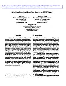
5 experimental results In this section, we quantify the energy consumption due to the transition overhead and discrete voltage levels and evaluate the energy saving performance of our proposed algorithms with both the randomly generated job sets and real-world examples. We first constructed and tested 100 randomly generated sets of 20 jobs each with our algorithms. The jobs are assumed to have worst-case execution time and release time uniformly distributed between [0,800] and [0,1000], respectively. The relative deadlines of the jobs are normally distributed with an average of 810 and a standard deviation of 280. We also assume that the transition energy overhead is ∆E = k|∆V | where k = 0.01. For each job set, we applied both Algorithm 1 and the improved algorithm (Section 4) with the overhead ranging from 0% (no overhead) to 100% of the average deadline of the jobs. A continuous voltage range between [0, 1] was used first to generate the comparison base. This process was repeated for a processor with 5 discrete levels (6 including idle) as with the AMD processor [1], and a processor with 14 discrete levels (15 including idle) as with the SA-1100 system [19]. The results were then normalized against the optimal voltage schedule without any overhead consideration (using LPEDF). The results are displayed in Figure 7. We also apply our algorithms to two real-world examples, i.e.,
10
Algorithm 5 Improved LPEDF with transition timing overhead 1: Input: The job set J , the time transition overhead length, ∆t, the energy transition overhead, ∆E, and the set of allowable speeds, V . 2: Output: A valid voltage Schedule T . 3: i = 0; // The critical interval index. 4: ins = 0; // The index of the most recently inserted interval. 5: while J is not empty do 6: i++; 7: Find the next critical interval Ti = [ts (i),t f (i)], its speed si , and the set of (references to) the jobs included in Ti , called Ji ; 8: [Ti ,Ji ,si ] = Discrete (Ti , Ji , si , V ) // Algorithm 4 9: if (i > 1 AND si > s(i−1) ) /* MONOTONICITY VIOLATION */ then 10: Undo changes in Bins ; //Restore related job timing information. 11: Jins = Ji ∪ Jins 12: Tins = Minimum Interval (Jins , sins ) // Algorithm 3; 13: J = J − Jins ; // Remove jobs in Jins from J 14: i − −; 15: end if 16: else ins = i; 17: while (∃Jk ∈ J AND [rk , dk ] ⊆ [ts (ins) − ∆t,t f (ins) + ∆t] /* EXECUTION VIOLATION */ do 18: Jins = Jins ∪ (all Jk ∈ J |[rk , dk ] ⊆ [ts (ins) − ∆t,t f (ins) + ∆t]); 19: Tins = Minimum Interval (Jins , sins ) // Algorithm 3; 20: J = J − Jins ; // Remove jobs in Jins from J 21: end while 22: Tneighbor = the set of all neighbors of Tins 23: changed = true; 24: while ∃Tk ∈ Tneighbor AND changed = true /* ENERGY OVERHEAD */ do 25: changed = f alse; 26: if (The combination of Tins with one of its neighbors, Tk ∈ Tneighbor consumes less energy than keeping Tins ) then 27: Jk = Jk + Jins 28: Tk = Minimum Interval (Jk , sk ) // Algorithm 3; 29: ins = k; 30: changed = true; 31: Tneighbor = the set of all neighbors of Tins 32: end if 33: end while 34: Bins = a record of timing changes to all jobs in J that intersect [ts (ins) − ∆t,t f (ins) + ∆t]; //Backup job timing requirements 35: Remove all jobs in J that fall within [ts (ins) − ∆t,t f (ins) + ∆t] from J ; 36: Squeeze [ts (i) − ∆t,t f i + ∆t] into a single time point and adjust the rest of jobs correspondingly; 37: end while
11
200
Base: Cont. Impr.: Cont. Base: 14 lvls Impr.:14 lvls Base: 5 lvls Impr.: 5 lvls
180
140
Above Optimal
Percent Increase in Energy Consumption
160
120 100 80 60 40 20 0 0
10
20
30
40
50
60
70
80
90
100
(Time Transition Overhead)/(Mean Deadline) x 100%
Figure 7: Energy consumption for randomly generated job sets. 70.0 Basic: Continuous Adv: Continuous Basic: 14 levels Adv: 14 levels Basic: 5 levels Adv: 5 levels
Percent Increase in Energy Consumption (above optimal)
60.0
50.0
40.0
30.0
20.0
10.0
0.0 0
100
200
300
400
500
600
Time Transition Overhead (
700
800
900
1000
s)
Figure 8: Energy consumption for CNC. CNC [16] and Avionics [14]. Our algorithms are tested with the transition timing overhead ranging from 5µs to 1ms for CNC job sets, and 5µs to 1.5ms for Avionics job sets. The results are shown in Figure 8 and 9, respectively. From Figure 7, 8, and 9, one can immediately notice that the transition overhead (both timing and energy) and discrete voltage levels can cause dramatic increase of energy consumption to the voltage schedule. And, as we expected, the energy consumption grows rapidly with the longer transition overhead and fewer available voltage levels. For example, from Figure 7, a processor model with 5 voltage levels and timing overhead as 5% of the average deadline will increase the total energy consumption by 24% comparing with the ideal processor model. Therefore, a valid and energy efficient voltage schedule scheme must take all these factors into considerations. Also, it is not difficult to see that our improved algorithm (Section 4) has a significant better performance than the basic one, 1.e. Algorithm 1. For example, in Figure 7, for the processor with 5 available voltage levels, our improved algorithm can save as much as nearly 50% of energy comparing with Algorithm 1 when the transition timing overhead is around 50% of the job deadlines. And the maximal energy saving can be as high as 17% for CNC example (Figure 8) and 82.5% for Avionics example (Figure 9).
5.1 AMD Mobile Athlon 4 Case Study In section 4.3 we explored various ways to account for energy transition overhead in our improved algorithm. In this section we explore the necessity of including this step by using the Moble Athlon 4 as a case study. 12
90.00 Base: Cont. Impr: Cont.
Percent In crease in Energy Above Op timal
80.00
Base: 14 lvls Impr:14 lvls Base: 5 lvls Impr: 5 lvls
70.00 60.00 50.00 40.00 30.00 20.00 10.00 0.00 0
200
400
600
800
Time Transition Overhead (
1000
1200
1400
s)
Figure 9: Energy consumption for Avionics. The Advanced Micro Devices’ Mobile Athlon 4 is a variable voltage processor using AMD’s PowerNOW! technology. It is representative of most current variable voltage systems in that it suffers from several practical limitations, such as energy and time transition overhead, and its performance levels are limited to several discrete levels, as shown in Table I from AMD’s PowerNOW! datasheet [1]. The actual power consumption for the maximum performance level and for the low-power stop-grant states are given in Table II from the same datasheet. Table I. Vlaid Voltage/Frequency Settings on the AMD Moblile Athlon 4. VCC CORE NOM Voltage 1.400 V 1.350 V 1.300 V 1.250 V Maximum Frequency 850 MHz 850 MHz 700 MHz 600 MHz 500 MHz 900 MHz 900 MHz 700 MHz 600 MHz 500 MHz 950 MHz 950 MHz 800 MHz 700 MHz 600 MHz 1000 MHz 1000 MHz 800 MHz 700 MHz 600 MHz 1100 MHz 1100 MHz 1000 MHz 800 MHz 700 MHz 1200 MHz N/A 1200 MHz 1000 MHz 900 MHz
1.200 V ≤ 500 MHz ≤ 500 MHz ≤ 500 MHz ≤ 500 MHz ≤ 600 MHz ≤ 600 MHz
Table II. Core Voltage and Current on the AMD Moblile Athlon 4. Frequency/State Voltage Maximum ICC Die Temperature (V) (A) (degrees Celcius) 850 MHz 1.40 15.71 95 900 MHz 1.40 17.14 95 950 MHz 1.40 17.14 95 1000 MHz 1.40 17.90 95 1100 MHz 1.40 17.90 95 1200 MHz 1.35 18.50 95 Halt/Stop Grant C2 1.20 2.00 95 Stop Grant C2 1.20 1.07 50 Stop Grant C3/S1 1.20 0.80 50 The equation Power = V I = Csw fV 2 gives a good approximation for the dynamic power consumption of a CMOS processor, neglecting short circuit and leakage power. Based on this equation and Tables I and II, the following table
13
of power characteristics can be derived: Table III. Power Characteristics of the AMD Moblile Athlon 4. Max Frequency Max Voltage Maximum ICC MaxPower (MHz) (V) (A) (W) 850 1.40 15.71 21.99 900 1.40 17.14 24.00 950 1.40 17.14 24.00 1000 1.40 17.90 25.06 1100 1.40 17.90 25.06 Transition 1.35 18.50 2.4
Csw (nF) 13.20 13.60 12.89 12.79 11.62 16.67
Whenever a performance transition is made, there are two 50 micro-second transitions that occur, whose ordering depends on whether the performance is being increased or decreased. For a performance increase, first the voltage is ramped up to the desired value, and then the frequency is adjusted, and for a decrease these steps are reversed. Together the transition takes 100 micro-seconds. During this time, the processor enters a stop-grant state. Note that it is unclear which stop-grant state power characteristics to use (it depends on the processor temperature), so the most pessimistic one from Table II, or 2 Amps at 1.2 Volts, was used for the transition row in Table III. The resulting energy overhead, if we assume this low power state for the entire transition of 100 micro-seconds, is given in (1): (1)
Energy(transition) = 100x10−6x2.4 = 2.4mJ
Based on the AMD model, this value is independent of the source and target voltage level/frequency. Of course, there will be some energy loss that is dependant on the two voltage levels, mainly from the DC-DC converter, but because the AMD’s system bus is not connected during a transition, this power is insignificant compared to the transition energy of the processor itself. For example, from the PhD Thesis of Thomas David Burd [3], the energy dissipation of their prototype voltage regulation system is given by the following equation: (2)
2 2 −VDD2 | ET RAN = η •CDD • |VDD1
Typical values given by Burd are η = 0.90 and CDD = 100uF. For the AMD processor, the maximum voltage switch would be 1.2 V to 1.4 V. Using these values, the max energy dissipation that is voltage level dependant would be: (3)
ET RAN = 0.9 • 100x10−6 • |1.42 − 1.22| = 0.0468mJ
This is the maximum energy consumption of the voltage regulator, and it is still less than 2% of the constant energy dissipated by the Athlon 4. For a typical real time system, where independent tasks are on the order of ms, the energy consumption for a transition from one interval to the next will be less than 1% of the total energy consumption. The following tables give the significance of the transition energy between constant voltage intervals of varying lengths using the 1100-MHz maximum-voltage Athlon 4. Table IV. Energy Overhead when the Transition length is 10% of Adjacent Voltage Intervals. Interval Interval Length Voltage Frequency Energy (uS) (V) (MHz) (mJ) T1 1000 1.2 700 11.72 Transition 100 0.24 T2 1000 1.3 800 15.71 TOTAL: 27.67 T1+T2 1875 1.3 800 29.74
14
14.000
EDF
Watts
13.000
12.000
AMD BASIC
11.000
AMD IMP
10.000
9.000
8.000
7.000
6.000 1 Task Set Random
Figure 10: Average power consumption of an AMD Moble Athlon 4 while executing randomly generated task sets.
Table V. Energy Overhead when the Transition length is 50% of Adjacent Voltage Intervals. Interval Interval Length Voltage Frequency Energy (uS) (V) (MHz) (mJ) T1 200 1.2 700 2.34 Transition 100 0.24 T2 200 1.3 800 3.14 TOTAL: 5.73 T1+T2 375 1.3 800 5.89
Table VI. Energy Overhead when the Transition length is 100% of Adjacent Voltage Intervals. Interval Interval Length Voltage Frequency Energy (uS) (V) (MHz) (mJ) T1 100 1.2 700 1.17 Transition 100 0.24 T2 100 1.3 800 1.571 TOTAL: 2.98 T1+T2 188 1.3 800 2.95 In the final case, where the intervals are the same size as the transition, combining the two intervals (T2’) will reduce the energy by 0.03 mJ. Cases where constant voltage intervals are on the same order as the transition interval are rare in practical examples, so implementing a complex algorithm to handle energy overhead (at least on the Athlon 4 and similar processors) may not be worth the effort. Using this model of the AMD Athlon’s power characteristics, we can find the average energy consumption in watts for our randomly generated task set. This is shown in figure 10. The Mobile Athlon 4 processor has a time transition overhead of about 100 microseconds, and power characteristics given in Table III. We can see that the difference between using the basic algorithm and the improved algorithm is about 7.4%, so the improved algorithm should be used in this case.
15
6 Summary In this paper, we studied the impact of practical limitations of current processors on voltage schedules. We have shown through examples and analysis that limitations such as transition overhead or discrete voltage levels can cause a theoretically optimal schedule to become invalid if not correctly accounted for during the scheduling process. Accounting for such limitations is not a trivial matter, as trying to make adjustments to the optimal schedule by inserting overhead between voltage intervals will likely cause jobs to miss their deadlines. We have presented two algorithms, which are guaranteed to yield a valid voltage schedule given an initially schedulable job set. The base algorithm offers a simple implementation, while the improved one can give significant energy savings over the base algorithm. Currently the optimality of our algorithms is not guaranteed, so further algorithm development may improve results even more. Also, for the scheduling process to give a practical voltage schedule for an even wider range of systems, other implementation details will need to be accounted for, including support for different transition models and other prioritization schemes, such as fixed priority scheduling. Future work must account for these limitations.
References [1] I. Advanced Micro Devices. Mobile AMD Athlon 4 Processor Model 6 CPGA Data SHEET. Publication #24319 Rev:E November 2001. [2] T. D. Burd and R. W. Brodersen. Design issues for dynamic voltage scaling. ISSCC, 2000. [3] T. D. Burd. Energy-Efficient Processor System Design. PhD Thesis, University of Berkley, Spring 2001. [4] A. Chandrakasan, S.S., and R. Brodersen. Low-power cmos digital design. IEEE Journal of Solid-State Circuits, 27(4):473–484, Apr 1992. [5] L. Chandrasena, P. Chandrasena, and M. Liebelt. An energy efficient rate selection algorithm for voltage quantized dynamic voltage scaling. ISSS, pages 124–129, 2001. [6] M. Fleischmann. Longrun power management: Dynamic power management for crusoe processors. RTSS, 1998. [7] I. Hong, G. Qu, M. Potkonjak, and M. B. Srivastava. Synthesis techniques for low-power hard real-time systems on variable voltage processors. RTSS, pages 178–187, 1998. [8] Intel. The intel xscale microarchitecture. Technical Summary, 2000. [9] T. Ishihara and H. Yasuura. Voltage scheduling problem for dynamically variable voltage processors. ISLPED, pages 197–202, Aug 1998. [10] W. Kim, J. Kim, and S. L. Min. A dynamic voltage scaling algorithm for dynamic-priority hard real-time systems using slack time analysis. DATE, 2002. [11] S. Lee and T. Sakurai. Run-time power control scheme using software feedback loop for low-power real-time applications. ASPDAC, 2000. [12] S. Lee and T. Sakurai. Run-time voltage hopping for low-power real-time systems. DAC, 2000. [13] C. L. Liu and J. W. Layland. Scheduling algorithms for multiprogramming in a hard real-time environment. Journal of the ACM, 17(2):46–61, 1973. [14] C. D. Locke, D. R. Vogel, and T. J. Mesler. Building a predictable avionics platform in ada: A case study. RTSS, 1991. [15] A. Manzak and C. Chakrabarti. Variable voltage task scheduling algorithms for minimizing energy. ISLPED, 2001. [16] N.Kim, M. Ryu, S. Hong, M. Saksena, C. Choi, and H. Shin. Visual assessment of a real-time system design: a case study on a cnc controller. RTSS, pages 300–310, Dec 1996.
16
[17] T. Okuma, T. Ishihara, and H. Yasuura. Real-time task scheduling for a variable voltage processor. ISSS, 1999. [18] T. Okuma, T. Ishihara, and H. Yasuura. Software energy reduction techniques for variable-voltage processors. IEEE Design and Test of Computers, 2001. [19] J. Pouwelse, K. Langendoen, and H. Sips. Dynamic voltage scaling on a low-power microprocessor. MOBICOM, pages 251–259, 2001. [20] J. Pouwelse, K. Langendoen, and H. Sips. Energy priority scheduling for variable voltage processors. ISLPED, 2001. [21] G. Quan and X.S.Hu. Energy efficient fixed-priority scheduling for real-time systems on variable voltage processors. DAC, pages 828–833, 2001. [22] Y. Shin and K. Choi. Power conscious fixed priority scheduling for hard real-time systems. Design Automation Conference, pages 134–139, 1999. [23] F. Yao, A. Demers, and S. Shenker. A scheduling model for reduced cpu energy. FOCS, pages 374–382, 1995. [24] Y. Zhang, X. Hu, and D. Chen. Task scheduling and voltage selection for energy minimization. Design Automation Conference, 2002.
17