information services beyond voice, such as telecommuting, video conferencing, interactive media, real-time Internet games, etc., at anytime, anywhere. To satisfy ...
A Resource Allocation Framework With Credit System And User Autonomy Over Heterogeneous Wireless Networks Zhu Han, Z.Jane Wang, and K.J. Ray Liu, Electrical and Computer Engineering Department, University of Maryland, College Park. Abstract— Future wireless networks will support the growing demands of heterogeneous services. Dynamic resource allocation is essential to guarantee quality of service (QoS) and enhance the network performance. We propose a novel resource allocation framework to cope with the time-varying channel conditions, co-channel interferences, and different QoS requirements in various kinds of services. We define a QoS measurement for delay sensitive applications. We introduce a credit system, where users have their autonomy to decide when and how to use their resources, and users can borrow or lend resources from the system. We also develop a simple feedback mechanism to report the system with the users’ QoS satisfaction levels and channel conditions. Then the system will adapt its resource allocation strategy according to the users’ feedbacks to favor the users with the bad QoS satisfaction levels or the good channels. We develop adaptive algorithms at both the user and system levels. From simulations, the proposed algorithms efficiently allocate the resources to different types of users. The users’ delay constraints are satisfied and the links can survive under a long period of bad channels.
operates are explained as follows: 1. Micro User Level: The goal is to let each user have the autonomy to decide when and how to use his resources according to the channel conditions and his application type. A credit system is constructed, where each user can borrow and lend resources from the system to transmit his information during different periods of times. By doing so, his resources can be “water filled” in time during the transmission, which not only guarantees the QoS, but also ensures the survival of link during the long period of bad channel conditions. 2. Macro System Level: The goal is to create an environment to improve the overall network performance under the users’ QoS constraints. It receives the feedbacks from the users to adapt the strategy for the environment, so that the user with the bad QoS satisfaction level or good channel condition can be allocated with more resources. Moreover, the system should encourage some users to sacrifice their performance temporarily, so that the overall network performance can be improved. These users may have the incentive to sacrifice in hope for the long-term payback. 3. Feedback Mechanism: The goal for feedback mechanism is to provide a simple but efficient way for each user to report his level of QoS satisfaction and channel condition, on which the system will be based to modify the optimization strategies.
I. Introduction The future wireless systems are expected to provide other information services beyond voice, such as telecommuting, video conferencing, interactive media, real-time Internet games, etc., at anytime, anywhere. To satisfy the growing demand of heterogeneous applications, one of the key objectives is to deliver flexible, variable rate services with high spectral efficiency. The time-varying channel conditions, co-channel interferences (CCI), and different quality of service (QoS) requirements are the potential challenges for the system design. Dynamic resource allocation is a general strategy to enhance the system performance. Current wireless systems choose single-to-interferencenoise ratio (SINR) as the QoS measure for voice communications. The resource allocation problem in the context of voice communications becomes power control problem [1], [2], [3], [4], [5], where the transmitted powers are constantly adjusted to achieves the users’ target SINR. It has been shown in [6], [7], [8], [9], [10] that jointly considering power control and adaptive modulation can provide a variable rate and variable power ability to combat with the time varying channel and CCI. In this paper, we concentrate on the resources such as the transmitted powers and throughput of MQAM modulation. The goal of this paper is to develop a framework of dynamic resource allocation with credit system and user autonomy for heterogeneous types of users, based on a QoS measure for delay sensitive applications. We view the problem at two levels: the macro system level and the micro user level. We also develop a feedback mechanism between the two levels. The motivations and how the framework
GLOBECOM 2003
The rest of the paper is organized as follows: In Section II, we give the system model and MQAM modulation throughput approximation. In Section III, we explain our resource allocation framework. In Section IV, we have numerical studies. In Section V, we offer the conclusions. II. System Model and Approximation For the purpose to illustrate the idea and performance of our proposed framework, we consider a K-user uplink Direct-Sequence CDMA system in a single cell where each user is assigned with a signature sequence and an antenna array of L elements is employed at the base station (BS). For simplicity, we assume a synchronous system with processing gain H. For uplink, over one bit period, the received signal vector of the antenna array at the BS is: y(t) =
K � �
Pk Gk bk sk (t)ak + n0 (t)
(1)
k=1
where Pk , bk , and sk are the transmit power, bit, and signature of user k, respectively, Gk is the uplink gain from user
- 977 -
0-7803-7974-8/03/$17.00 © 2003 IEEE
2. Macro System Level: The system employs adaptive algorithms to optimally assign different users their shares of resources according to their throughput ranges and other constraints such as the system feasibility [9], [10] and the maximum power. We assume perfect estimations of channel conditions. The problem is given by:
k to the BS, the spatial signature ak is the array response vector of user k, and n0 (t) represents the white Gaussian noise vector. We apply the chip rate filtering and sample at the chip rate. The sampled output is represented as: Y=
K � �
Pk Gk bk sk aTk + N0
(2)
k=1
where Y has the size H-by-L, whose lth column represents the outputs of the lth antenna element, sk is the signature sequence of user k, and N0 represents the space and time white noise with zero mean and variance σ 2 . Suppose we apply a two-dimensional temporal-spatial linear filter Xi to decode the bit bi in the MMSE sense [8]. The filter Xi with size H-by-L is: 2 Xi = arg min E[|tr(XH i Y) − bi | ] Xi
max γi ,Pi
T 2 Pi Gi |tr(XH i si ai )| . H T 2 H 2 k�=i Pk Gk |tr(Xi sk ak )| + σ tr(Xi Xi )
−c2
Γi 2Ti −1
i
(4)
i
B. User Satisfaction Factor
(5)
where c1 ≈ 0.2 and c2 ≈ 1.5 for MQAM when BER is small. From (5), for a specific BER, the ith user’s throughput is � � (6) Ti = log2 1 + ci3 Γi ci
2 where ci3 = − ln(BER i . i /c ) 1
III. Resource Allocation Framework
In this subsection, we will address how to quantify the USF which shall help adjust the resource allocation strategies, i.e., the system adapts its algorithms so that the resources are more likely to be allocated to the unsatisfied users in the future. Due to the concerns on bandwidth and real-time feature, only limited feedback is allowed, therefore, the USF should be represented efficiently, for example, by a simple real value. Suppose that data stream is transmitted in frames. Each frame has the length of M . In this paper, the USF represents whether or not a user can transmit its frame within the desired time. We define N as the the transmit time with the strictest delay constraint. The time when the frame is completely transmitted is n� and n� ≥ N . The current time is n. For each user, a parameter α is selected when he is admitted to the network, where α depicts the tolerance of delay for this user. We assume at each time n ≥ N , the user has probability of 1 − α to finish the current frame. Then we can depict the probability for the total frame transmit time n� as a geometric distribution:
A. Problem Formulations In order to implement the proposed ideas and the framework for resource allocation, we propose to formulate and solve the problems heuristically at the micro user level and the macro system level as:
Pr (n� = N + i) = (1 − α)αi , i = 0, 1, . . . .
(8)
Different types of payloads have different delay tolerances, which are categorized as:
1. Micro User Level: According to the transmission history, the users calculate user satisfaction factor (USF) for their QoS. The users’ tolerance for delay will affect the value of USF. At time n, according to the USF and his current channel condition, the ith user feedbacks the system with an acceptable throughput range [Timin (n), Timax (n)]. The problems include how to define USF and how to update the acceptable throughput range.
GLOBECOM 2003
(7)
where P = [P1 . . . PK ]T , u = [u1 . . . uK ]T with ui = H T 2 γi σ 2 tr(XH i Xi )/(Gi |tr(Xi si ai )| ), γi is the targeted SINR such that Γi ≥ γi , D = diag{γ1 . . . γK }, and 0 if j = i, T 2 [Fij ] = Gj |tr(XH i sj aj )| if j �= i. Gi |tr(XH si aT )|2
(3)
Adaptive modulation provides the system with the ability to adjust the effective bit rate (throughput), according to the interference and channel conditions. MQAM is a modulation method that has high spectrum efficiency. Without loss of generality, we assume that each user has the unit bandwidth and the throughput is continuous. Let Ti denote the ith user’s throughput, which is the number of bits sent within each transmitted symbol. The BER can be approximated as a function of the received SINR and throughput [6], [7], [8], [11] given by: BERi ≈ c1 e
Ti (n)
i=1
Feasibility: (I − DF)P ≥ u, Throughput: Timin (n) ≤ Ti (n) ≤ Timax (n), s.t. Maximum Power: Pi ≤ Pmax ,
where tr(·) is the trace operation. The ith user’s SINR at the output of the joint temporal-spatial filter is given by: Γi = �
K �
- 978 -
1. Strict Delay Constraint: In this case, α = 0, P (n� = N ) = 1, which means the frame must be transmitted before or at time N . It fits the voice payload. 2. Soft Delay Constraint: Here 0 < α < 1, the estimated time to transmit the frame is N = N − 1 + 1/(1 − α). It fits the video/image or data payload. 3. No Delay Constraint: α = 1, so P (n� = N + i) = 0, ∀ i ≥ 0, which means the user can suffer arbitrary transmission delay. It fits some generic data payload that is not time sensitive.
0-7803-7974-8/03/$17.00 © 2003 IEEE
In the traditional wireless network, when a user is admitted to the system, his parameters are predefined to the system. Then the system assigns the resources to the user, according to his parameters. There is no feedback from the user to the system during the transmission to reflect whether or not the user really gets the desired QoS, even if the wireless channels may fluctuate. So we need to define USF for user’s real QoS satisfaction such that the system can adapt its resource allocation � scheme under different n−1 conditions. Define Tihis (n − 1) = j=1 Ti (j). We define the ith user’s proposed USF at time n as: USFi (n) = α th
2.5
i
Tmax(n) and Tmin(n)
3
i
2
1.5
1
0.5
.
(9)
1. USF > 1: user can finish transmission even before time N and is over satisfied. He can use a lower rate to transmit during the rest of times. 2. USF = 1: in this case, user’s QoS is exactly satisfied. If he uses the average rate M/N , he can finish the frame at time N . 3. 0 ≤ USF < 1: when USF becomes smaller, the user becomes more unsatisfied and has to transmit more in the rest of times.
0.4
0.6
0.8
1
1.2
1.4
1.6
1.8
2
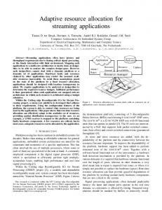
Fig. 1. Throughput Range vs. USF for different κi
The physical meaning of κi (n) is the ratio of the most current throughput at time n−1 over average desired throughput, which can represent the relative channel condition. In the micro user level, the ith user’s goal is to report the system with the current acceptable throughput range [Timin (n), Timax (n)], according to his USF and channel condition. If USF ≥ 1, there is no need for the user to transmit at the rate larger than M/N . So we have Timin (n) = 0. We assume the USF is uniformly distributed from [1, ∞] and we select exponential function for Timax (n) as: Timax (n) = (M/N )e−(USFi −1)/κi (n) . (11) So the average Timax (n) for this USFi is equal to the throughput Ti (n − 1). If 0 ≤ USF < 1, we use power function to determine the throughput as:
C. Credit System, User Autonomy, Resource Awareness Similar to the economy system, we introduce concepts of credit system, user autonomy, and resource awareness to resource allocation. At a specific time, since the channel varies, the user may transmit more or less than the desired throughput. A credit system is constructed to allow lending or borrowing resources and record user’s transmission history. If the user experiences a bad channel, he will be more aggressive to transmit in the future when the channel becomes better. In the proposed approach, the user will provide a higher acceptable throughput range to demand more resources. On the other hand, if the channel is still bad, he will delay requesting resources until the channel becomes better. So the user has his own autonomy to decide when and how to use the resources. In order to optimize the users’ autonomy for resource usages, the users need to know their current channel conditions, i.e., they have resource awareness. If the channels are good, users prefer to spend more resources for transmission, else they will wait until the channels become better. Suppose Tˆimax and 0 be the maximum and minimum allowable throughput provided by the system for the ith user. To quantify the resource awareness, we define:
GLOBECOM 2003
0.2
i
the If the i user maintains the average rate his = M (n−1)/T estimated time to finish the frame is nest i i . So the physical meaning of USF is the probability that if nest ≥ N . If nest < the user can transmit after nest i i i N , the user is over satisfied and USF > 1. The value of USF represents the user’s QoS satisfaction level and has the following implications:
Ti (n − 1) . M/N
0
USF
Tihis /(n − 1),
κi (n) =
κ i = 0.5 κ i= 1 κ i= 2
3.5
0
M (n−1) −N ) ( T his i
Tmax (n),Tmin (n) vs. USFi for different paramenters i i
4
(10)
Timax (n) = Tˆimax − (Tˆimax − M/N )(USFi )κi (n)
Timin (n) = (M/N )(1 − (USFi )κi (n) ).
(12)
(13)
In Fig. 1, we give an example on how the throughput ranges change with different USF and channel conditions. Here M/N = 2, Tˆimax = 4, and κi = 0.5, 1, 2 respectively. By jointly considering the USF and channel condition κi (n), the adaptive algorithm for each user is given by: Micro User Throughput Range Algorithm 1. Factors Calculation: calculate USFi (n), κi (n). 2. Throughput Range Calculation: Update acceptable throughput range. 3. Feedback: report the range [Timin (n) Timax (n)] to the macro system level for optimization. 4. Transmit Data: According to the rate Ti (n) assigned by the system. D. Adaptive Algorithm for Macro System Level At the macro system level, the goal is to select the best throughput allocation method to different users to generate the maximum overall system throughput under the constraints. In [10], we developed a projected gradient method. In this paper, we will develop a much faster barrier method by using the idea from semi-definition programming [12].
- 979 -
0-7803-7974-8/03/$17.00 © 2003 IEEE
The basic idea for the barrier method is to add barrier functions to the optimization goal such that the sum approaches negative infinity if the constraints are not satisfied. On the other hand, if the constraint is satisfied, the barrier function doesn’t affect the optimization goal. The barrier function is commonly approximated by logarithmic barrier functions given by: Iconstraint ≈ Φ1 + Φ2 + Φ3 + Φ4
(14)
where Φ1 is for Ti (n) > Timin (n), Φ2 is for Ti (n) < Timax (n), Φ3 is for feasibility, and Φ4 is for Pmax :
� ln(Ti (n) − Tmin (n)), Ti (n) > Tmin (n), Φ1 = (15) −∞, otherwise.
� ln(Tmax (n) − Ti (n)), Ti (n) < Tmax (n), Φ2 = (16) −∞, otherwise.
ln det (I − DF), if (I − DF) > 0, Φ3 = (17) −∞, otherwise.
�K i=1 ln (Pmax − Pi ), if Pi < Pmax , Φ4 = (18) −∞, otherwise. The approach for barrier method is to solve the constrained optimization problem by a sequence of unconstrained problems. We rewrite (7) as: max f = t˜ γi ,Pi
K �
Ti (n) + Iconstraint
IV. Simulation Results We assume a linear array of omni directional antennas with L = 4 elements equispaced at half a wavelength. All K = 80 users are uniformly distributed within the range of [r0 , r] with r0 = 50m being the closest distance and r = 1000m being the cell radius. H = 64. The mobile users move in arbitrary directions with speeds uniformly distributed in the range [0, 40] kph. We consider three phenomena in the propagation model: the path loss factor is 3.5 and a constant factor is chosen to yield a 30dB loss at 1m; the slow shadowing fading is modelled as a lognormal distribution with 3dB standard deviation; three paths with equal power Rayleigh fading with negligible delay spreads are considered. The fading is generated by the Jakes model with a π/10 angle spread. The update is taken every 10ms. In Fig. 2 and Fig. 3, we show the throughput and USF for different types of users at different transmission times. Here the packet size M = 30, Tˆimax = 4, Tˆimin = 0, ∀i, and N = 15. We assume user 1 to 20 have α = 0, user 21 to 40 have α = 0.9, user 41 to 60 have α = 0.95, and user 61 to 80 have α = 1. The figure is brighter when the throughput is large and USF is large. The behaviors of different types of users are summarized as: 1. α = 0: USF is equal to 0 or 1 and the transmission rate is always high because each user has to transmit his frame before the strict deadline. 2. 0 < α < 1: The transmission rate is determined by the channel condition. When the users with good channel conditions finish their frames early, their USF will be high so that they demand less throughput in the future. 3. α = 1: USF is always equal to 1. The transmission is concentrated when the system is less busy. For example, the throughput is high around time 50 when most of users from No. 21 to 60 finish their transmissions.
(19)
i=1
where t˜ is a value that increases from iteration to iteration. The barrier functions become more and more like the ideal barrier function, when t˜ is increasing. So the solution is more and more close to the optimal solution. Within each iteration, we use Newton method [12] to solve the unconstrained optimization problem. The algorithm is given by: Barrier Method for Macro Throughput Maximization 1. Initial: Γ = any feasible value, t˜ = t0 > 0, β > 1, δ > 0. 2. Repeat: • Start at Γ, compute Γ∗ by maximizing f , using Newton Method: 1. Compute Newton step vnt and decrement λ2 . vnt = − �2 f −1 � f λ2 = �f T �2 f −1 � f 2. quit if λ2 is stable. 3. Line search: compute step size t� by backtracking line search. 4. Update: Γ=Γ−t � ∗vnt . • Γ=Γ∗ , calculate P. • if m/t˜ < δ, return Γ and P. • t˜ = β t˜. where m is the iteration number for barrier method, δ determines the accuracy of the proposed algorithm, t� is the optimal step for the Newton method, t0 is the initial value for barrier function, whose value determines the convergence rate of the first iteration, and β is the constant that t˜ is multiplied in each iteration.
GLOBECOM 2003
From the simulation results, we can see that the proposed algorithms allocate system resources according to the service types, USF, and channel conditions. Fig. 4 shows typical delay spreads for three schemes: our proposed scheme, Round Robin [13], and greedy scheduling (Traditional scheduling to maximize system throughput with Ti (n) ∈ [0, Tˆimax ], ∀i). We order the users from the best channel to the worst. M = 100, N = 55, and α = 0.9. Round Robin is a strict fair scheduling, but it has the poorest performance. Scheduling has the highest system throughput, but the users suffer arbitrary delays. While in the proposed scheme, the delays are more strict around the desired value. In Fig. 5, we show the throughput loss for different types of services and different α. If all the users have arbitrary delay constraint α = 1, system will have the largest average throughput and we use this value to compare with the other situations. When all the users have the same delay constraint (0%), if α is too small, the system will be infeasible. This is because the links can not survive in the long bad channel conditions. When α > 0.83, the users can
- 980 -
0-7803-7974-8/03/$17.00 © 2003 IEEE
GLOBECOM 2003
- 981 -
0-7803-7974-8/03/$17.00 © 2003 IEEE