applied sciences Review
A Review of Distributed Fibre Optic Sensors for Geo-Hydrological Applications Luca Schenato
ID
National Research Council, Research Institute for Geo-Hydrological Protection, Corso Stati Uniti 4, I-35127 Padova, Italy;
[email protected]; Tel.: +39-049-829-5812 Academic Editor: Miguel González Herráez Received: 5 August 2017; Accepted: 27 August 2017; Published: 1 September 2017
Featured Application: Distributed fibre optic sensors for geo-hydrological applications: a comprehensive review about methodology, weaknesses, and strengths. Abstract: Distributed optical fibre sensing, employing either Rayleigh, Raman, or Brillouin scattering, is the only physical-contact sensor technology capable of accurately estimating physical fields with spatial continuity along the fibre. This unique feature and the other features of standard optical fibre sensors (e.g., minimal invasiveness and lightweight, remote powering/interrogating capabilities) have for many years promoted the technology to be a promising candidate for geo-hydrological monitoring. Relentless research efforts are being undertaken to bring the technology to complete maturity through laboratory, physical models, and in-situ tests. The application of distributed optical fibre sensors to geo-hydrological monitoring is here reviewed and discussed, along with basic principles and main acquisition techniques. Among the many existing geo-hydrological processes, the emphasis is placed on those related to soil levees, slopes/landslide, and ground subsidence that constitute a significant percentage of current geohazards. Keywords: distributed optical fibre sensors; landslide; soil erosion; subsidence; levees
1. Introduction The era of optical fibre sensors (OFSs) started 50 years ago with the granting of the Fotonic sensor (U.S.03327584; 27 June 1967) [1], almost together with the advent of fibre-optic communication technology. The many features offered by OFSs that make this technology surpass conventional ones have been widely addressed by several review papers, and include the immunity to electromagnetic interference, minimal invasiveness and lightweight, multi-parameters sensing, ease of multiplexing, and remote powering/interrogating capabilities. Furthermore, it is the only technology that enables the distributed monitoring of some physical fields (e.g., strain, temperature) along the fibre (i.e., with spatial continuity of the measurands). This particular type of OFS is called a distributed optical fibre sensor (DOFS) and exploits scattering processes occurring in the fibre. The features mentioned above along with this unique ability of DOFSs made them perfect candidates for sensing applications in harsh environments characterised by large geographical extension and requiring a high spatial density of sensing points like geo-hydrological monitoring. Early applications of DOFSs into geo-hydrological monitoring can be dated to more than 25 years ago, first with distributed temperature measurement campaigns in soil levees and embankments, but other examples regarding slope stability and landslide monitoring by distributed strain sensing soon followed. In the following sections, the application of DOFSs to some critical geo-hydrological processes will be presented and discussed. A great effort has been undertaken to include as many significant
Appl. Sci. 2017, 7, 896; doi:10.3390/app7090896
www.mdpi.com/journal/applsci
Appl. Sci. 2017, 7, 896
2 of 42
papers as possible, but at the same time, we are aware that many others have been published about these topics. Ultimately, the included references have been carefully chosen to support the understanding of key issues and potentials of DOFS technology in this field and with the aim of offering a comprehensive review of the use of DOFSs in practical geo-hydrological applications, both in-situ and in physical models. Firstly, the fundamental principles at the basis of distributed optical fibre sensing are introduced with a brief review of the acquisition techniques that are currently implemented in DOFSs. In particular, the three different processes employed in DOFSs—namely Raman, Brillouin, and Rayleigh scattering—are addressed separately, discussing their respective weaknesses and strengths. In the second part of the paper, the application of DOFSs to geo-hydrological monitoring is reviewed and discussed. The review is about the monitoring of levees, slope and subsidence processes causing the main common geomorphic hazards. Other minor applications are not considered in this review. Similarly, the paper includes neither approaches where distributed techniques are used only to interrogate concatenations of single point sensors [2,3] nor transducers inducing losses at discrete points along the fibre (e.g., employing bending) [4,5]. 2. Distributed Optical Fibre Sensors The common assumption that enables the sensing feature in optical fibres is that the surrounding environment affects the local properties of the fibre itself. As mentioned above, at the basis of all the DOFSs, there are the following three scattering processes: Rayleigh, Raman, and Brillouin scattering [6]. Despite the different scattering processes, the sensing mechanism is the same for all of them: the back propagating light generated when an optical signal is fed into the fibre is used to probe the local properties of the fibre, and therefore to figure out the changes in the surrounding environment. Regarding Raman and Brillouin scattering, environmental conditions directly affect the corresponding backscattered signals used as probes. For example, the fibre’s local temperature intrinsically affects the intensity of the anti-Stokes Raman scattered signal, and this dependence has been successfully exploited to implement distributed temperature sensors (DTSs). Similarly, local temperature and strain intrinsically influence frequency and intensity of Brillouin-scattered signal, and Brillouin scattering is used to implement distributed temperature and distributed strain sensors (DSSs). Conversely, Rayleigh-based distributed sensing is less straightforward: Rayleigh scattering is in fact intrinsically independent of almost any external physical fields that may affect the surrounding environment. Therefore, rather than the scattering process per se, Rayleigh scattering is used to measure environment-dependent propagation effects. Attenuation/gain, as well as phase interference and polarisation rotation, are among the propagation effects that are currently detected to implement Rayleigh-based DOFSs. Of course, Raman and Brillouin scattering can also be used in principle to measure these propagation effects, but direct sensing mechanisms are preferred due to their simplicity and effectiveness. In the following sections, the principle of distributed sensing for the three scattering processes are briefly overviewed: for an extensive description of working principles and recent research achievements (which are outside the scope of this paper), we direct the reader to some excellent reviews and resources [7–11]. 2.1. Rayleigh-Based Distributed Sensing Rayleigh scattering is an elastic process resulting from local variations of refractive index due to heterogeneity and density fluctuation of the material [12,13]. Because of that heterogeneity, a small portion of the incident light is scattered at specific points called scattering centres. These scattering centres are randomly distributed along the fibre and act as weak reflectors, reflecting the light in all directions. However, only the fraction of the scattered light falling within the angle of acceptance of the fibre in the opposite direction is captured by the guiding structure of the fibre itself, and back-propagates to the input.
Appl. Sci. 2017, 7, 896
3 of 42
The backscattered signal has peculiar properties [14]: first of all, the intensity of incident light backscattered at a scattering centre is attenuated over the round-trip length (i.e., from the fibre input to the centre’s position). Furthermore, on average, each portion of fibre illuminated at any time by a single pulse is expected to radiate the same backscattered intensity broadly. This effect can be easily revealed with a broadband pulsed incident light. However, when a narrowband laser is used, each scattering centre illuminated by the same probe pulse contributes coherently to the backscattered light. Overall, the intensity and phase of the light reflected all along the fibre are determined by the vector sum of all electric fields radiated by the scattering centres, and therefore depend on the amplitude and position of scattering centres along the fibre. Both the amplitude and position are randomly distributed but fixed in time as long as the relative phase difference (i.e., optical distance) among illuminated scattering centres does not change [15]. In the case of broadband sources, these coherent effects still present, determining only a tiny fluctuation around the average scattering intensity. At the basis of all Rayleigh DOFSs, there is the detection of the counter-propagating signal, and in turn, of the attenuation along the fibre. To this aim, two main approaches can be followed: • •
To determine the attenuation in the time domain, with pulse signals (i.e., to determine the roundtrip impulse response of the fibre), known as optical time domain reflectometer (OTDR). To characterise the attenuation in the frequency domain, with a frequency-modulated continuous wave signal (i.e., to determine the roundtrip frequency response of the fibre), known as optical frequency domain reflectometer (OFDR).
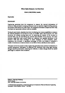
Notably, the intensity of the backscattered signal in single-mode fibres is rather small (approximately 55 dBs lower than that of the probe light), and this represents one of the main challenges to the implementation of Rayleigh-based DOFSs—either in time or frequency domain. 2.1.1. Optical Time Domain Reflectometry Historically speaking, OTDR was developed almost simultaneously by two independent research groups: Barnosky and Jensen at Hughes Research Laboratory [16] and Personick at Bell Telephone Laboratories [17]. In particular, Parsonick applied the technique directly to installed links and firstly provided an expression for the received signal levels. The first ever proposed DOFS was indeed based on a polarisation-sensitive OTDR scheme (POTDR) [18,19], while the original setup of Barnesky, Jensen, and Personick was proposed as a distributed sensor only in 1983 by Hartog et al. [20]. Figure 1 shows the working principle of conventional OTDRs. In that implementation, a broadband source is used to generate light pulses; a circulator (or a coupler) separates the forward path from the backward one; a photodetector measures the light intensity; and dedicated electronics drive the devices, process the data, and record the measurements. In standard OTDR, the best spatial resolution that can be obtained is half the length of the pulse, but in real applications, other factors (e.g., low signal-to-noise ratio, SNR) may impair the performance and make the resolution worse. An overall reduction of SNR is indeed observed for reduced pulse lengths, as less energy is injected in the fibre: overall, in conventional OTDR, the SNR is roughly proportional to the square of the spatial resolution [9]. To circumvent this limit, other time-domain techniques were proposed over the years, exploiting correlation [21,22], pulse coding [23,24], or photon-counting (ν-OTDR) [25–27]. Another time-domain approach uses the coherent nature of Rayleigh backscattering originated by a narrowband light source: as mentioned above, the backscattered signal is the coherent vectorial sum of fields generated at scattering centres and encodes the information about their position. Like in a distributed multi-path interferometer, the received backscattered signal experiences speckle noise known as Rayleigh fading [28,29]. Despite the randomness distribution of centres’ positions and corresponding relative optical phases, the resulting “interference pattern” represents a snapshot of scattering centres’ positions along the fibre. If the fibre is perturbed (e.g., strained or heated/cooled), the relative positions of scattering centres change (i.e., the relative optical phase difference), causing
Appl. Sci. 2017, 7, 896
4 of 42
the interference pattern to change. This change can be tracked, and the mechanism is exploited—also commercially—to implement DOFSs for dynamic strain and vibration detection (distributed vibration sensor, DVS or distributed acoustic sensor, DAS) with spatial resolution comparable to that of conventional OTDRs. This time-domain solution is called phase-OTDR (or φ-OTDR) [30–34]. Incident Circulator pulsed light
Rayleigh Scattering
Light source (*)
Sensing Fibre
(*) for OTDR: Pulsed laser; for I-OFDR: intensity modulated Mainframe
Photodiode
CW laser with swept RF frequency
Figure 1. The principle of operation of the OTDR and I-OFDR schemes (CW: continuous wave; OTDR: optical time domain reflectometer; I-OFDR: incoherent optical frequency domain reflectometer; RF: radio frequency). Modified from [9].
2.1.2. Optical Frequency Domain Reflectometry As discussed above, optical frequency domain reflectometry aims at characterising the frequency response of the fibre under roundtrip propagation. Instead of using a pulse signal, the source is modulated either in intensity or frequency. Optical frequency domain reflectometry comes in two variants: • •
Incoherent OFDR or I-OFDR , obtained by modulating the optical intensity with radio frequency (RF) signals; Coherent OFDR, obtained by sweeping the optical frequency.
In these two variants, the sensing information is encoded on an RF or an optical carrier, respectively. The basic setup of an I-OFDR is similar to that of a conventional OTDR (Figure 1), where the pulsed source is replaced by a continuous wave light modulated in amplitude by an RF signal. The RF signal frequency is linearly swept in a given bandwidth to probe the frequency response of the fibre [35,36]. Similar to conventional OTDR, I-OFDR spatial resolution is inversely proportional to the system bandwidth, here corresponding to the bandwidth swept by RF modulation. Nonetheless, owing to the RF modulation, this approach can benefit from electrical heterodyne detection, in general resulting in better performance compared to OTDR [37,38]. Despite that, at the moment there are no commercial implementations of Rayleigh-based I-OFDR, probably due to the outstanding performance achieved by the coherent counterpart. The basic setup of coherent OFDR is shown in Figure 2. The light from the source—which is optical frequency-modulated—interferes coherently with the light that was emitted a short time before and scattered back from a certain distance along the sensing fibre [39]. If one assumes that the sweep is linear, the frequency difference between these two light signals is proportional to the propagation time delay along the sensing fibre, and therefore, to distance. This means that the instantaneous beat frequency measured at the detector is mapped to a specific position along the fibre.
Appl. Sci. 2017, 7, 896
5 of 42
Mainframe
frequency
Optical
Swept Laser
Local Oscillator
Sensing Fibre Time
Figure 2. The principle of operation of the coherent OFDR scheme.
The spatial resolution δz is in this case determined by the wavelength scanning range ∆λ (or, equivalently, by the frequency scanning range, ∆ f ). It reads δz = c/(2n∆ f ) = λs λ f /(2n∆λ), where c, n, λs , and λ f are the speed of light, the effective refractive index of the fibre, and lower and upper wavelengths of the frequency scan, respectively [40]. At the same time, if the sweep time is slow enough, the electrical bandwidth needed to manage the frequency sweep can be reasonably modest, down to some MHz. Indeed, the expression of maximum beat frequency, f max , is given by f max = L/(δz tsweep ) = γτmax , where L, tsweep , γ, and τmax are the length of the fibre, the frequency sweep duration, the slope of the frequency sweep (Hz/s), and the maximum fibre delay, respectively. This means that a 1 km-long fibre can be sampled with 10 cm of spatial resolution by sweeping the frequency over 1 GHz in 1 ms (γ = 1 THz/s) and with a maximum beat frequency of 10 MHz. These values show the advantage of coherent OFDR over other time-domain techniques: high spatial resolution is achieved with a wavelength sweep of some tens of nanometres and a relatively small electric bandwidth. From early OFDR implementations over short fibres more than 30 years ago [41], it took a while to reach longer distances, mainly due to the need for coherent sources capable of very linear frequency sweep [42]. To circumvent the issue of the nonlinearity of the frequency sweep, schemes integrating an additional reference interferometer were proposed [43]. The problem of lack of coherence of the source—which limits the measurement range—was also tackled (e.g., by introducing phase-compensation techniques) [44]. Furthermore, the introduction of balanced photodiodes in polarisation diversity scheme determined a further improvement of the sensitivity of heterodyne detection. The resolution of some centimetres over tens of kilometres [45], or millimetres over a few kilometres [46] are now possible—at least in laboratory setups. Moreover, very recently, a commercial polarisation-sensitive OFDR (POFDR) appeared in the market, mainly for birefringence measurements and devices characterisation. To conclude this section, we report the performance of some commercial Rayleigh-based interrogators (Table 1). Please note that the table includes only devices that manufacturers specifically intended for sensing applications.
Appl. Sci. 2017, 7, 896
6 of 42
Table 1. Performances of some commercial Rayleigh-based interrogators (sources: producers’ datasheets, technical notes, and scientific papers). Type
Fibre Type
Sensing Range
Measurand Spatial Measurand Resolution Resolution
Acquisition Time
ν-OTDR (*)
SMF/ MMF/POF
40 km (SMF)
10 cm
n/a
n/a
minutes
φ-OTDR
SMF SMF
100 km up to 40 km
5m 4m
Vibration
n/a (1 Hz–2.5 kHz) n/a n/a (0.1 Hz–20 kHz) 20–500 µs
1 cm 3 cm 5.2 mm 5.2 mm 1.3 mm
0.1 °C/1 µε Temperature >0.5 °C/>4.1 µε /