International Journal of Power Electronics and Drive System (IJPEDS) Vol. 6, No. 3, September 2015, pp. 554~566 ISSN: 2088-8694
554
A Review of the DTC Controller and Estimation of Stator Resistance in IM Drives Naveen Goel, R.N. Patel, Saji Chacko Electrical & Electronics Department, Shri Shankaracharya Group of Institutions, Junwani, Bhilai (CG), 490020, India
Article Info
ABSTRACT
Article history:
In recent years an advanced control method called direct torque control (DTC) has gained importance due to its capability to produce fast torque control of induction motor. Although in these systems such variables as torque, flux modulus and flux sector are required, resulting DTC structure is particularly simplistic. Conventional DTC does not require any mechanical sensor or current regulator and coordinate transformation is not present, thus reducing the complexity. Fast and good dynamic performances and robustness has made DTC popular and is now used widely in all industrial applications. Despite these advantages it has some disadvantages such as high torque ripple and slow transient response to step changes during start up. Torque ripple in DTC is because of hysteresis controller for stator flux linkage and torque. The ripples can be reduced if the errors of the torque and the flux linkage and the angular region of the flux linkage are subdivided into several smaller subsections. Since the errors are divided into smaller sections different voltage vector is selected for small difference in error, thus a more accurate voltage vector is selected and hence the torque and flux linkage errors are reduced. The stator resistance changes due to change in temperature during the operation of machine. At high speeds, the stator resistance drop is small and can be neglected. At low speeds, this drop becomes dominant. Any change in stator resistance gives wrong estimation of stator flux and consequently of the torque and flux. Therefore, it is necessary to estimate the stator resistance correctly. This paper aims to review some of the control techniques of DTC drives and stator resistance estimation methods.
Received Feb 19, 2015 Revised Jul 20, 2015 Accepted Aug 5, 2015 Keyword: Artificial neural network Adaptive neuro fuzzy Direct torque control Inference system Space vector modulation
Copyright © 2015 Institute of Advanced Engineering and Science. All rights reserved.
Corresponding Author: Naveen Goel, Departement of Electrical & Electronics, Shri Shankaracharya Group of Institutions, Junwani, Bhilai (CG), 490020, India. Email:
[email protected]
1.
INTRODUCTION D.C. motors have been used widely during the last century in applications where variable-speed operation was needed, because its flux and torque can be controlled easily by means of changing the field and the armature currents respectively. DC motors have basically two drawbacks, which are the existence of commutators and brushes. These disadvantages imply not only periodic maintenance but also affect the efficiency of the machine. Induction motors are widely used in many industrial applications due to their mechanical robustness and low cost. Induction motors are the most widely used motors among different electric motors because of high level of reliability, efficiency and safety.The ac drives are broadly classified [1-2] as (i) Scalar Controlled and (ii) Vector controlled.
Journal homepage: http://iaesjournal.com/online/index.php/IJPEDS
555
ISSN: 2088-8694
Scalar Control: scalar control is based on steady-state relationship with magnitude and frequency only without space vector orientation. In V/f scalar control scheme terminal voltage is proportional to the frequency, which results in an approximately constant stator flux. Vector Control: In vector controlled drives voltage, current and flux space vectors are controlled both in steady state and during transients. Coordinate transformation (3 phase to d-q axis) to new field coordinates is a key component of standard giving a linear relationship between control variable and torque. Vector control techniques can be classified as indirect or feed forward method and direct or feedback method depending on the method of unit vector generation for vector rotation. F. Blaschke [3] invented the Direct Vector control method. In this method the unit vector is generated from the flux vectors which are estimated using machine terminal voltage and current [4].
2.
DIRECT TORQUE CONTROL A type of performance enhanced scalar control called DTC control was proposed by Takahashi [5] and M. Depenbrock [6] in 1980s. It is a high performance technology which is developed after the Vector Control [7]. Torque and flux of a DTC- based drive are controlled in a closed-loop manner without using current loops in comparison with the conventional vector controlled drives. The DTC based drives require the knowledge of stator resistance only, thereby decreasing the associated sensitivity to parameter variations [8]. The control gives fast response. It is simple to implement due to absence of close loop current control, traditional PWM algorithm and vector transformation. The electromagnetic torque and stator flux linkage are estimated in stator reference frames using the measured stator voltages and currents. The machine model is dependent on stator resistance only, the stator q and d axis flux linkages φqs, φds can be obtained through the integration of the difference between the phase voltage and the voltage drop in the stator resistance as below [9-10] ∅
ʃ
and ∅
ʃ
Where, as the flux linkage phasor magnitude and angle are: ∅
∅ tan
∅ ∅ /∅
In terms of stator flux, electromagnetic torque is given by: 3 2
2
∅
∅
Two different hysteresis comparators for flux and torque are used to generate control signals as shown in figure 1. Flux hysteresis comparator is two level type while torque comparator is three level type. These comparators use flux and torque instantaneous error value as input and generate control signals as output. In the conventional DTC drive as shown in figure 1, the flux and torque pulsation can be high if the switching frequency of the inverter is not adequate. There is sluggish response during start up or during a change of flux or torque error and also the flux position. There is no method to distinguish between very large and small errors. Thus, the switching vectors chosen for large errors are the same as the switching vectors chosen for time control during normal operation. A number of implementation of the scheme has been made depending on how the currents and voltages are measured & estimated.
IJPEDS Vol. 6, No. 3, September 2015 : 554 – 566
IJPEDS
ISSN: 2088-8694
556
Figure 1. Block Diagram of DTC
3.
DIFFERENT CONTROL TECHNIQUES OF DTC There are different control techniques for DTC, which have evolved over the years.
3.1. Modified DTC In conventional DTC there are high torque and flux ripples. In most of the works [11-17] the authors rectified these drawbacks with the usage of SVM technique. SVM technique can be classified in two ways, (a) Modified DTC scheme-I:in this scheme flux torque controllers are replaced by PI controllers and SVM technique (Figure 2) and, (b) Modified DTC scheme –II: in this scheme the torque error and flux error are made as sliding mode controllers (Figure 3). Both the schemes result in less ripples with less switching frequency but modified DTC scheme-II is superior in terms of robustness to parameter variations. But, it has a drawback of chattering in slide mode control.
Figure 2. Modified DTC Scheme- 1 Block Diagram
Figure 3. Modified DTC Scheme-2 Block Diagram
A Review of the DTC Controller and Estimation of Stator Resistance in IM Drives (Naveen Goel)
557
ISSN: 2088-8694
Figure 4. System Diagram of the Modified DTC IM Drive Tang L. et al. [18] propose system where in place of switching table and hysteresis controllers, a PI controller and reference flux vector calculator are used to find out the reference stator flux linkage vector as depicted by Figure 4. A space vector modulator is used to generate the control signals for inverter. A special SVM pattern is used to reduce the switching frequency. The current harmonics are greatly reduced in modified DTC. The response time of the basic DTC is shorter than that of modified DTC. Modified DTC features low torque ripple, low flux ripple and almost fixed switching frequency. Kumsuwan et al. [19-20] propose that the performance of DTC can be improved by application of voltage modulation by replacing the lookup table of voltage vector selection. This voltage modulation is based on SVM with constant switching frequency. In this paper DTC is based on decoupled control of both stator flux and torque which is different from DTC SVM. This technology used the relationship between torque slip angular frequency and rotor angular frequency for controlling stator flux angle. The drawback of the estimation of the stator flux based on voltage model using open loop integration is dc drift and saturation problem. In this paper improved stator flux estimation by integrating algorithm with an amplitude limiter in polar coordinates is used to overcome these problems. 3.2. DTC with Two Level or Multilevel Inverter Srinivasa Rao S. and Vinay Kumar T. [21] propose switching state algorithm for cascaded two level inverters (Figure 5). In proposed DTC method applied voltage space vector is a function of rotor speed. The proposed method is implemented for low speed (25-50% of rated speed), very low speed (less than 25% of rated speed), high speed (above 50% of rated speed) and for optimum flux and torque ripple. The drawback of this type of converter is the voltage imbalance produced in the capacitors of the DC link. Xavier del Toro Garcia et al. [22] and Cirrincione M. et al. [23] designed three level voltage source inverter as shown in Figure 6, which increases the number of voltage vectors so that the torque & flux ripples are reduced. This VSI has advantages like lower dv/dt, less harmonic distortion and lower switching frequency. The drawback of this type of converter is the voltage imbalance produced in the capacitors of the DC link. Three level inverter is having a disadvantage of more complexity in the circuit and is more expensive, but it cuts the cost of filters.
IJPEDS Vol. 6, No. 3, September 2015 : 554 – 566
IJPEDS
ISSN: 2088-8694
558
Figure 5. Three level inverter configuration using cascading of two level inverter
Figure 6. Three level neutral point clamped voltage source inverter
3.3 DTC with Current Source Inverter Selvam N. Panneer et al. [24] present CSI fed induction motor drive with DTC. The torque and stator flux linkages are estimated using measured stator voltages and currents. This estimation is dependent only on stator resistance. CSI fed drives as shown in Figure 7, find applications in high power drives such as fan drives, where fast dynamic response is not needed, because of the advantages of inherent four quadrant operation and reliability. The stator resistance is compensated as shown in Figure 8 using stator current phase error. PI adaptive compensator is used for measured stator current only.
A Review of the DTC Controller and Estimation of Stator Resistance in IM Drives (Naveen Goel)
559
ISSN: 2088-8694
Figure 7. Basic scheme of DTC CSI-fed IM drive
Figure 8. Block diagram schematic of the adaptive stator resistance compensator
3.4 Fuzzy Control Scheme Abdalla T.Y et al. [25] and Zalman M. and Ivica Kuric I. [26] used fuzzy controller is in which torque error and stator flux angle are taken as input variables and duty ratio control (s) as output variable as shown in Figure 9. By the implementation of fuzzy controller torque and current ripples are reduced in transient and steady state response.
Figure 9. Block diagram of fuzzy duty ratio control Soliman H.F.E. and Elbuluk M.E. [27] compare the basic DTC with PI and DTC with fuzzy controller as shown in Figure 10. The value of Kp changed according to the operating conditions, hence the authors suggest replacing the PI controller with the fuzzy logic controller.
IJPEDS Vol. 6, No. 3, September 2015 : 554 – 566
IJPEDS
ISSN: 2088-8694
560
Figure 10. DTC system with PI and FLC controller for speed loop The fuzzy input vectors are motor speed variations Δw and the acceleration d/dt(Δw); while fuzzy output is the change in reference torque. The Simulink results show better dynamic performance of induction motor when using DTC with fuzzy logic in comparison with fixed PI controller. Abdalla T.Y et al., [28] deliberate that the PID controller may not provide the control performance during the variations in plant parameters & operating conditions. The fuzzy based PI controller is the self adaption PI controller as shown in Figure 11. In this method scaled values of speed error and change of speed error are used by the fuzzy controller to update the values of Kp and Ki.
Figure 11. Fuzzy PI-Controller based DTC Sayeed Mir et al. [29] find the relationship between the change in stator resistance and stator current (Figure 12). PI and fuzzy logic controllers are used to compensate the changes in stators resistance. The fuzzy estimator gives better performance. At low speed also fuzzy resistance estimator is able to operate the controller.
Figure 12. Direct torque control with fuzzy resistance estimator A Review of the DTC Controller and Estimation of Stator Resistance in IM Drives (Naveen Goel)
561
ISSN: 2088-8694
Zidani F et al., [30] describe the stator resistance estimation using fuzzy logic. This approach is based on the phase and magnitude error between the estimated stator flux and the filtered one. For kth sampling interval the errors are as noted below which serve as input having three triangular member functions each. e1 (k)= │φs(k)│-│φsf(k)│ e2 (k)=phase (φsf) - phase (φs) The limitations of conventional DTC and AI used DTC like torque ripples, ripples in flux and error in stator resistance estimation at low speed were overcome by estimating the changes in stator resistance due to temperature change. By observing the results it could be concluded that the estimator performs well under dynamic operating condition also.
4.
ESTIMATION OF STATOR RESISTANCE The stator resistance changes due to change in temperature during the operation of machine. At high speeds, the stator resistance drop IsRs is small and can be neglected. At low speeds, this drop becomes dominant compared to Vs. Therefore, any change in stator resistance gives wrong estimation of stator flux and consequently of the torque and flux. Therefore it is necessary to estimate the stator résistance. Different techniques are used for the estimation of stator resistance. The advantage of MARS is its simple implementation requirement. The technique proposes calculation of the parameter value to be identified in two different ways. The first value is calculated from reference inside the control system. The second is calculated from measured signal. One of the two values should be independent of the parameter which is to be estimated.
Figure 13. MARS based stator resistance estimation scheme The difference between the two values is an error signal as shown in Figure 13 and is used to drive an adaptive mechanism either using a PI, I controller, Fuzzy logic, ANN or ANN and Fuzzy logic. Ozkop E. and Okumus H.I. [31] and Yingfei W et al. [32] propose a model reference adaptive system to estimate the stator resistance for direct torque controlled induction motor. The main idea of MRAS is that the equation with no estimated parameter is taken as reference model, and the equation with estimated parameter is taken as the regulated model. The two models have the different outputs with the same physical significance. The errors of the two outputs are used to frame the adapter laws to regulate the parameter of the regulated model and output of object is controlled to follow the output of reference model. The voltage model is taken as reference model to obtain the rotor flux. The current model is taken as the regulated model to obtain the rotor flux. Bilal A et al. [33] used a reactive-power based reference model derived in both motoring and generation modes but one of the disadvantages of this algorithm is its sensitivity to detuning in the stator and rotor inductances. Blaha P. and Vaclavek P. [34] present a stator resistance identification algorithm for AC induction motor. During the operation of the motor the Rs is determined from the RMS value of the voltage, current &actual active power. The disadvantage is the dependency of the estimate on the level of magnetic IJPEDS Vol. 6, No. 3, September 2015 : 554 – 566
IJPEDS
ISSN: 2088-8694
562
flux excitation. The offline measurement of stator inductance on excitation current is proposed to solve this problem. Change in Rs is due to change in temperature. There are three types of Rs estimation. First one is zero sequence model based Rs estimation by solving least squares minimization problems. In this method, the access to neutral of the stator winding is needed for current injection. It has the disadvantage of heating of the winding. The second one is based on DC model. In this method, the input impedance of the motor is directly equal to Rs for DC signal. The third method requires knowledge of induction motor model. This paper presents third method. This algorithm operates online and requires no external excitation. The following are the different methods for estimation of stator resistance of induction motors for vector controlled drives: Estimation of Stator Resistance using PI Estimation of Stator resistance using Fuzzy Logic Mamdani Type fuzzy logic controller Estimation of Stator resistance using ANN Estimation of Stator resistance using Fuzzy Logic and ANN Change in Stator resistance due to temperature variations Estimation of Stator resistance using EKF Estimation of Stator resistance using Lunberger Obsever Technique 4.1 Estimation of Stator Resistance using PI Lee Byeong-Seok and Krishnan R. [35] present a solution to track the stator resistance so that the performance degradation and a possible instability problem can be avoided. Proportional-Integral (PI) adaptive compensator using only the measured stator currents is applied. An analytic expression to evaluate the stator current command from the torque and stator flux linkage commands is derived and presented. This scheme requires two filters and one PI controller apart from the existing electromagnetic torque and stator flux linkages calculator in the drive controller. A signal proportional to stator resistance change is developed using the error between the reference and actual stator current phasor. This error is processed through a PI controller for application in the controller. Stator resistance parameter adaptation results in restoring the precise and accurate estimation of stator flux linkage magnitude and its position in the controller. 4.2 Estimation of Stator Resistance using Fuzzy Logic In DTC if the stator resistance varies due to heating, the performance of the system will suffer because the actual flux does not match with the calculated flux. Zhong L et al. [36] describe an online fuzzy observer for the stator resistance estimation. The fuzzy model is used with three inputs current, speed & operation time. It was verified with experiment that fuzzy observer estimates the variation of the stator resistance quite well, with error less than 6.3%.The difference between DTC and DSC is the shape of the path along which the flux vector is controlled to follows. In DTC the path is circle and in DSC it was a hexagon. Chauhan S et al. [37] describe that large torque ripples are produced in DTC due to torque errors. To reduce the torque ripple the errors have to be divided into several intervals. In conventional DTC it is not possible; hence fuzzy control is associated with SVM technique. The space vectors are generated by two fuzzy logic controllers. First one is for flux and second one is for torque control. The usage of fuzzy controllers instead of PI controllers permits a faster response and more robustness. The use of SVM technique which provides a constant inverter switching frequency results in small torque ripple and current distortion. But, because the number of rules is too high, the speed of fuzzy reasoning will be affected. Korkmaz F et al. [38] propose a fuzzy based stator flux estimator that optimizes itself to regulate the stator flux reference value regarding to the motor load. Adaption of flux to load variation can be done in 3 ways (i) flux control as a function of torque (ii) flux control based on loss model and (iii) flux control by a minimum loss search controller. Authors propose the first way i.e. flux controlled as a function of torque without need of any motor parameters by using fuzzy algorithm. Fuzzy stator flux optimizer uses just torque error and change on torque error with any motor parameter. Simulation results shows that the proposed system with optimized stator flux has much smaller ripple in torque with respect to time than the conventional DTC at all working conditions. Ebrahimi A. and Farshad S. [39] developed Mamdani type fuzzy direct torque controller first and then rules are modified using stator current membership function. Stator current is chosen as the control parameter. During startup or during changes in reference flux & torque, a fuzzy logic based switching vector process is developed. In Mamdani type fuzzy three inputs are flux error, torque error and the position of the stator flux space vector i.e. A Review of the DTC Controller and Estimation of Stator Resistance in IM Drives (Naveen Goel)
563
ISSN: 2088-8694
Flux error (eΦ) ∆ds = ds* –ds Torque error (eT) ∆Ts = Ts* -Ts Stator flux space vector is Φs. In the improved system one more input, stator current is introduced to reduce the over current problem. 4.3 Estimation of Stator Resistance using ANN Cabrera L.A et al. [40] used ANN for on line tuning of stator resistance. For the estimation of stator resistance ANN inputs are current error and change in current error output of neural that gives ∆Rs (k) which is added to the previous value of Rs (k-1) to give an estimate for the actual value of Rs. ∗
∆ ∆ Where
∗
1 the stator is command current and
I k
i
k
i
is the actual current, with
defined as:
k
Figure 14. On-line set up for training the neural network
The results show that the large neural network gives more accurate results (Figure 14). The only drawback of using more neurons in the hidden layers is the increased in number of weights so the calculation is more complicated and lengthy. 4.4 Estimation of Stator Resistance using Fuzzy Logic and ANN Jalluri S R. and Ram B .V .S. [41] improved conventional DTC using ANN and fuzzy logic (as shown in Figure 15). ANN is used for speed estimation. A fuzzy system is used to tune the PI of the speed controller and an ANN estimates the stator resistance. This method of AC drive system is intended for an efficient control of the torque & flux without changing the motor parameters. The sensitivity of the DTC is eliminated by on line estimation of stator resistance. The DTC is based on the evaluation of two quantities that are stator flux and torque. Exact evaluation of Vs requires accurate measurement and good evaluation of Rs. The value of Rs which varies with temperature needs either an accurate thermal model or an evaluation and estimation method.
IJPEDS Vol. 6, No. 3, September 2015 : 554 – 566
IJPEDS
ISSN: 2088-8694
564
Figure 15. DTFC functional block diagram
Figure 16. Block diagram of stator resistance estimation using ANFIS estimator
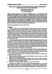
The input – output training data is used by the ANFIS (Figure 16). Inputs are stator current and stator winding temperature with respect to time and output is the stator resistance.
5.
CONCLUSION
Direct torque control (DTC) of induction motors (IMs) requires an accurate knowledge of the magnitude and angular position of the controlled flux. In DTC, the flux is conventionally obtained from the stator voltage model, using the measured stator voltages and currents. This method utilizes open loop pure integration suffering from the well known problems of integration effects in digital systems, especially at low speed operation range. An attempt is made in this paper to review some of the existing identification techniques for control techniques of DTC. Often Parameter values that are used within the drive controller are identified offline i.e. at the stage of drive initialization, but inevitably they vary during the drive operation thus deteriorating performance. This has led to the development of online parameter estimation. An attempt is made in this paper to review some of the existing identification techniques. Knowledge of actual stator resistance plays an important role in the performance of DTC.
REFERENCES [1] [2] [3] [4]
Bose B.K. High Performance Control and Estimation in AC drives. 23rd International Conference on Industrial Electronics, Control and Instrumentation (IECON 97). 1997; 2: 377-385. Kerkman R.J, Skibinski G.L., Schlegel D.W. AC drives: year 2000 and beyond. Fourteenth Annual Applied Power Electronics Conference and Exposition (APEC '99). 1999; 1: 28-39. Blaschke F. The principle of field orientation as applied to the new trans-vector closed loop control system for rotating field machines. Siemens Review XXXIX. 1972; 5: 217–220. Finch J.W., Damian Giaouris D. Controlled A.C. Drives. IEEE Transactions on Industrial Electronics. 2008; 55(2): 481-491.
A Review of the DTC Controller and Estimation of Stator Resistance in IM Drives (Naveen Goel)
565 [5] [6] [7] [8] [9] [10] [11] [12] [13] [14] [15] [16] [17] [18] [19] [20] [21] [22] [23] [24] [25] [26] [27] [28] [29] [30] [31]
ISSN: 2088-8694
Takahashi I., Noguchi T. A New Quick-Response and High-Efficiency Control Strategy of an Induction Motor. IEEE Transactions on Industry Applications. 1986; I A-22(5): 820-827. Depenbrock M. Direct Self-Control (DSC) of Inverter-Fed Induction Machine. IEEE Transactions on Power Electronics. 1998; 3(4): 420-429. Wang Yingfei, Cheng Qiming, Cheng Yinman, Hu Xiaoqing, Xue Yang. Simulation Research on Speed Sensorless Direct Torque Control System Based on MRAS. Journal of Computational Information Systems. 2011; 7(9): 30703076. Ebrahimi A., Farshad S. Speed Control in Fuzzy Direct Torque Control Induction Motor Drives. World Scientific and Engineering Academy and Society, Proceedings of the 8th WSEAS International Conference on Electric Power Systems, High Voltages, Electric Machines (POWER '08). 2008: 47-54. Korkmaz F., Cakir M. F., Korkmaz Y., Topaloglu I. Fuzzy Based Stator Flux Optimizer Design for Direct Torque Control. International Journal of Instrumentation and Control Systems. 2012; 2(4): 41-49. Lee Byeong-Seok, Krishnan R. Adaptive Stator Resistance Compensator for High Performance Direct Torque Controlled Induction Motor Drives. Industry Applications Conference, Thirty-Third IAS Annual Meeting Conference Record of the 1998 IEEE, Missouri USA. 1998; 1: 423-430. Babu P.S., Ushakumari S. Modified Direct Torque Control of induction motor drives. Recent Advances in Intelligent Computational Systems (RAICS). 2011: 937-940. Buja G., Casadei D., Serra G. Direct stator flux and torque control of an induction motor. Theoretical analysis and experimental results in Proc. IEEE (IECON' 98). 1998; 1: T50-T64. Lascu C., Boldea I., Blaabjerg F. A modified direct torque control for induction motor sensor less drive. IEEE Transactions on Industry Applications. 1998; 36(1): 122-130. Habetler T.G., Profumo F., Pastorelli M., Tolbert L. M. Direct torque control of induction machines using space vector modulation. IEEE Trans. on Industrial Applications. 1992; 28: 1045-1053. Lai Y. S., Shihn T. Y., Kuan Y. S., Huang H. C. A novel inverter control technique for direct torque control drives. Power Electronics Technology, (in Chinese). 1997; 39: 71-77. Lai Y.S., Chen J.H. A new approach to direct torque control of induction motor drives for constant inverter switching frequency and torque ripple reduction. IEEE Transactions on Energy Conversion. 2001; 16: 220-227. Casadei D., Serra G., Tani A. Implementation of a Direct Torque Control Algorithm for Induction Motors Based on Discrete Space Vector Modulation. IEEE Transactions on Power Electronics. 2000; 15(4): 769-777. Tang L., Zhong L., Rahman M.F, Hu Y. An investigation of a modified direct torque control strategy for flux and torque ripple reduction for induction machine drive system with fixed switching frequency. Industry Applications Conference, 2002. Conference Record of the 37th IAS Annual Meeting. 2000; 2: 837-844. Kumsuwan Y., Srirattanawichaikul W. and Premrudeepreechacharn S. Reduction of Torque Ripple in Direct Torque Control for Induction Motor Drives Using Decoupled Amplitude and Angle of Stator Flux Control. ECTI Transactions on Electrical Engineering, Electronics, and Communications. 2010; 8(2): 187-196. Rajendran R., Dr. Devaranjan N., A comparetive performance analysisof torque control schemes for induction motor drives. International Journal of Power Electronics and Drive System (IJPEDS). 2012; 2(2): 177-191. Srinivasa Rao S., Vinay Kumar T. Direct torque control of induction motor drives for optimum stator flux and torque ripple. IEEE Ninth International Conference on Power Electronics and Drive Systems (PEDS). 2011: 952955. Xavier del Toro Garcia, Antoni A., Marcel G. Jayne, Phil A. Witting, Vicenç M. Sala and Jose Luis Romeral. New DTC Control Scheme for Induction Motors fed with a Three-level Inverter. AUTOMATIKA – 46. 2005; 1(2): 73– 81. Cirrincione M., Pucci M., Vitale G. A novel direct torque control of an induction motor drive with a three-level inverter. IEEE Bologna Power Tech Conference Proceedings. 2003; 3: 7. Selvam N. Panneer , Prasanna M. Arul, Raj I. Gerald Christopher, Dr. Rajasekaran V. On-Line Stator Resistance Tuning of DTC Control CSI Fed IM Drives. International Journal of Power Electronics and Drive System (IJPEDS). 2012; 2(2): 225-231. Abdalla T.Y., Hairik H.A, Dakhil AM. Minimization of torque ripple in DTC of induction motor using fuzzy mode duty cycle controller. 1st International Conference on Energy, Power and Control (EPC-IQ). 2010; 7(1): 237-244. Zalman M., Ivica Kuric I. Direct torque and flux control of induction machine and fuzzy controller. Journal of Electrical Engineering. 2005; 56(9): 278–280. Soliman H.F.E., Elbuluk M.E. Direct Torque Control of a Three Phase Induction Motor Using a Hybrid PI/Fuzzy Controller. Industry Applications Conference 2007, Conference Record of the IEEE 2007 42nd IAS Annual Meeting. 2007: 1681-1685. Abdalla T.Y., Hairik H.A, Dakhil AM. Direct torque control system for a three phase induction motor with fuzzy logic based speed Controller. 1st International Conference on Energy, Power and Control (EPC-IQ). 2010; 6(2): 131-138. Sayeed Mir, Malik E. Elbuluk, Donald S. Zinger. PI and Fuzzy Estimators for Tuning the Stator Resistance in Direct Torque Control of Induction Machines. IEEE Transactions on Power Electronics. 1998; 13(2): 279-287. Zidani F., Diallo D., Benbouzid M.E.H., Nait-Said R. Direct Torque Control of Induction Motor with Fuzzy Stator Resistance Adaptation. IEEE Transactions on Energy Conversion. 2006; 21(2): 619-621. Ozkop E., Okumus H.I. Direct Torque Controlled Induction Machine with MRAS Based Stator Resistance Estimation. 3rd International Conference on Electrical and Electronics Engineering (ELECO 2005).
IJPEDS Vol. 6, No. 3, September 2015 : 554 – 566
IJPEDS
ISSN: 2088-8694
566
[32] Yingfei W., Cheng Q., Cheng Y., HU X., Xue Y. Simulation Research on Speed Sensorless Direct Torque Control System Based on MRAS. Journal of Computational Information Systems. 2011; 7(9): 3070-3076. [33] Bilal A., Umit O., Aydin E., Mehrded E. A Comparative Study on Non- Linear State Estimators Applied to Sensorless AC Drives: MRAS and Kalman Filter. 30th Annual Conference of the IEEE Industrial Electronics Society. Busan, Korea. 2004. [34] Blaha P., Vaclavek P. AC Induction Motor Stator Resistance Estimation Algorithm. 7th WSEAS International Conference on Electric Power Systems, High Voltages, Electric Machines, Venice, Italy. 2007: 86-91. [35] Lee Byeong-Seok, Krishnan R. Adaptive Stator Resistance Compensator for High Performance Direct Torque Controlled Induction Motor Drives. Industry Applications Conference, Conference Record of the 1998 IEEE Thirty-Third IAS Annual Meeting, Missouri USA. 1998; 1: 423-430. [36] Zhong L., Rahman M.F., Lim K.W., Hu, Y.W., Xu, Y. A fuzzy observer for induction motor stator resistance for application in direct torque control. International Conference on Power Electronics and Drive Systems. 1997; 1: 91-96. [37] Chauhan S., Topno Pretty N., Vyas Dhaval R. Minimization of Torque Ripple of Induction Motors using Fuzzy Direct Torque Control. IJCA Proceedings on International Symposium on Devices MEMS, Intelligent Systems & Communication (ISDMISC). 2011; 7: 11-15. [38] Korkmaz F., Cakir M.F., Korkmaz Y., Topaloglu S. Fuzzy based stator flux optimizer design for direct torque control. International Journal of Instrumentation and Control Systems (IJICS). 2012; 12(4): 41-49. [39] Ebrahimi A., Farshad S. Speed Control in Fuzzy Direct Torque Control Induction Motor Drives. Proceedings of the 8th WSEAS International Conference on Electric Power Systems, High Voltages, Electric Machines (POWER '08). 2008: 47-54. [40] Cabrera L.A., Elbuluk M.E., Husain I. Tuning the Stator Resistance of Induction Motors Using Artificial Neural Network. IEEE Transactions on Power Electronics.1997; 12(5): No779-787. [41] Jalluri S.R., Dr. Ram B.V.S. Direct torque control method Using fuzzy logic for Induction Motor Drives. International Journal of Advanced Research in Electrical, Electronics and Instrumentation Engineering. 2012; 1(4): 275-281.
BIOGRAPHIES OF AUTHORS Naveen Goel was born in Haridwar (U.P.), India in 1968. He received his Bachelor degree in Electrical Engineering from Jiwaji University, Gwalior (M.P.) in India in 1992 and Masters in Electrical Engineering (Power Electronics) from Shri Govind Ram Sakseria Institute Technology and Science, Indore, M.P, India in 2006. He is a faculty of Electrical and Electronics Engineering at Shri Shankaracharya Technical Campus, Bhilai, C.G, India and is currently pursuing his PhD from Swami Vivekanand Technical University, Bhilai C.G., India. He is the author of 3 International Journal and Conference and 5 National conferences. His area of research interest is Power Electronics and drives, Custom power devices, application of soft computing techniques for estimation and fault detection in Electric Drives. R. N. Patel did his Ph. D. in the area of Power Systems from the Indian Institute of Technology (IIT) New Delhi, INDIA in the year 2003. Prior to this he obtained his M. Tech. from IIT Delhi and graduate degree in Electrical Engineering from SGSITS Indore. Dr. Patel served as a Faculty in the Electrical Engineering department at IIT Roorkee from the year 2003 to 2006. He has also served in Faculty position at the Birla Institute of Technology and Science, Pilani. Presently he is working as Professor in the department of Electrical and Electronics Engineering at SSGI (Shri Shankaracharya Technical Campus), Bhilai, INDIA. Dr. Patel has many publications in various international journals of repute, presented his research at various international conferences and has also organized many national Workshops and Conferences. He is a recipient of prestigious ‘Career Award for Young Teachers’, from AICTE-New Delhi, INDIA. Dr. Patel has successfully handled many research projects, sponsored (/funded) by AICTE, New Delhi and Department of Science and Technology (DST), Govt. of INDIA, New Delhi. Saji T Chacko was born in Chattisgarh,(C.G), India in 1968. He received his Bachelor degree in Electrical Engineering from Pt. Ravishankar University Raipur,(C.G),India in 1990 and Masters in Electrical Engineering (Power Electronics) from Samrat Ashok Technological Institute, Vidisha ,M.P, India in 2005. He is a faculty of Electrical and Electronics Engineering at Shri Shankaracharya Technical Campus, Bhilai, C.G, India and is currently pursuing his PhD from Maulana Azad National Institute of Technology, Bhopal, M.P, India. He is the author of 3 International Journal and Conference and 5 National conferences. He is an elected member of the Electrical Engineering Board of Institution of Engineers (IE), India. His area of research interest is Power Electronics and drives, Custom power devices, application of soft computing techniques for estimation and fault detection in Electric Drives
A Review of the DTC Controller and Estimation of Stator Resistance in IM Drives (Naveen Goel)