Advances in Computational Sciences and Technology ISSN 0973-6107 Volume 9, Number 1 (2016) pp. 11-23 © Research India Publications http://www.ripublication.com
A review on image enhancement and color correction techniques for underwater images S. S. Sankpal1 and S. S. Deshpande2 1
Assistant Professor, Department of E&Tc, PVPIT Budhagaon, Maharashtra, India, E-mail:
[email protected] 2 Professor, Department of Electronics Engg, WCE, Sangli, Maharashtra, India, E-mail:
[email protected] Abstract Degradation of underwater images is different from normal images. In underwater imaging light interact with water in two ways, scattering and absorption. The scattering and absorption together is called attenuation of light in water. This attenuation is wavelength dependent. Because of scattering and absorption, underwater images are affected by back scattering, forward scattering and absorption of light in water. As a result of which the images are degraded, and also dominated by green or blue color. Water is not only source of degradation, but underwater images are also affected by suspended particles and dissolved compounds in water. The degradation also depends upon depth of water, day time, geographical location, source of light and physical properties of water etc. Many underwater applications need clear underwater images. Clear underwater images can be achieved by image enhancement and restoration techniques. The image enhancement techniques are simpler and faster than restoration processes because it does not require any prior knowledge about the parameters of water, where image has been captured. Underwater image enhancement techniques includes contrast enhancement, non uniform illumination correction, and color correction techniques. Among these very few researchers attempted a problem of non uniform illumination correction. Some image enhancement and color correction techniques for underwater images are reviewed in this paper. The quality metrics used to test the image quality are also discussed in the paper. Keywords: underwater image enhancement, color correction, non uniform illumination correction, haze removal, back scattering, forward scattering, absorption.
12
S. S. Sankpal and S. S. Deshpande
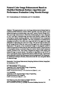
1. Introduction Development of autonomous underwater vehicles, advancement in underwater infrastructure and curiosity about underwater world has increased research opportunities in underwater image and video processing. Image of any object is created by reflection of incident light (artificial light or sunlight) from the object. In case of underwater imaging the light is interacted with water when it is travelled from source to object and back to the camera. This causes degradation of image. As water is 800 times denser [1] than air, the degradation problem of underwater images is different from normal images. Underwater image degradation is caused by three phenomena, absorption, back scattering and small angle forward scattering of incident and/or reflected light [2]. These three components of responsible degradation are shown in figure 1. The first problem is absorption of light, which is wavelength dependent. Red is attenuated most and blue least. As light travels deeper and deeper the colors are dropped off. First red color is diminished, then orange, yellow and so on but the blue color travels longest. So the underwater images are dominated by blue color [3]. Second problem encountered is backscattering. In this scattering the light is reflected back without reaching the object. This scattering is caused by reflection of light in backward direction by particles in water and water itself. As this reflected light is in the field view of camera without reaching the object, it does not contribute to image and degrade the image contrast [2]. Third problem is small angle forward scattering. This is forward scattering of incident and/or reflected light by small angle. Which introduce serious resolution loss [2]. All the above three components are function of distance of the object from camera, depth of the object and characteristics of water (like turbidity, salinity, pH value etc.) [2,3]. Underwater imaging is having many applications like, Study of underwater biodiversity, Marine biology research, Maintenance of in-sea installation [3], Long range search [3], Vision system of aquatic robots etc. Most of these applications required clear underwater images, so that objects in the image are clearly visible and can be recognized using their shape and color. This can be achieved by either image restoration or image enhancement techniques [3].
Fig. 1: Scattering and Absorption of light in water
A review on image enhancement and color correction techniques
13
But image restoration techniques required model of degradation, which required model parameters like attenuation coefficient, turbidity, time, depth, etc [3]. These parameters are scarcely available with captured images and without which the restoration is impossible. Whereas image enhancement techniques do not require any such parameters, so it is simpler and faster than restoration techniques. 2. Underwater Image Enhancement Techniques The characteristics of water are varying with depth of water, with geographical location, day time etc, and it is difficult to measure all the parameters of water. So these parameter values are scarcely available with the captured images. Underwater image enhancement techniques do not require any prior knowledge about these parameters of water. Because of this reason image enhancement techniques are simpler, faster and preferred for many applications. Some of the underwater image enhancement techniques are discussed here. Mortazavi et al [4] used multispectral images and extract underwater objects by subtracting back scattering from the image. The image model given by equation (1) I (x,y)=b (x,y) + a (x,y)*F (x,y) (1) where b (x,y) is back scattered component, a (x,y) is attenuation factor and F (x,y) the scene in clear condition at a specific wavelength at spatial pixel position (x,y). Recovery of the intensity of pixel Ῑ (x,y) can be achieved by rearranging equation (1) as Ῑ (x,y) (2)
In the above equation b (x,y) is estimated by statistical model based on minimization of cost function presented by Oakley and Bu[5]. But in this method back scattering in the image is considered constant which not true. Then the algorithm of cost function is extended to a variable spatial distribution of optical backscatter. Zhang et al [6] considered water as imaging object. The water object is removed using Zadeh-X gray/chroma transform given as (3) Where CH = 0,1,2 for red, green and blue, k is expansion or contraction factor, here k=255, Theta and Delta values are transformation parameters, T(CH,x,y) and O(CH,x,y) are chroma values at (x,y) pixel. The image optimization is done by completing Zadeh-X transformation with Delta = f(ALL) * ALL, here f(ALL)=2 the method is called removing water-attenuation compensation-optimization in short RCO method. Yussof et al [7] presented Contrast Limited Adaptive Histogram Equalization (CLAHE) to overcome the noise amplification problem caused by histogram equalization. The algorithm combines two images of CLAHE that are applied on to two color models, RGB and HSV. CLAHE limits the amplification by clipping the histogram. In RGB model CLAHE is applied only on R (red) channel and in HSV model CLAHE is applied on S and V channel. HSV image is then converted into RGB and integrated using Euclidean norm.
14
S. S. Sankpal and S. S. Deshpande
Huimin Lu et al [8] presented algorithm that used Dark Channel Prior and find out depth map in the image and remove backscattered component. Then adaptive cross image filter is used for image smoothing by preserving edges. The filter is derived from guided filter by He et al[9] and Bilateral filter by S. Paris & F. Durand [10]. Karthiga1 R. and Ashokraj M [1] proposed color constancy algorithm to resolve the luminance problem due to the artificial light source in underwater images. It is patch based illuminance estimation and correction. Main task of color constancy algorithm is color correction and removal of effect of defective light source. Color constancy is used to provide the better image enhancement. The procedure is as follows. Initially sampling is performed, then illuminance estimation and finally the color correction has been done. Color correction is done by diagonal model. The diagonal model is given by equation (4), Ic = u,c Iµ (4) c Where I is the transformed image captured under the canonical illuminant, I µ is the image captured due to the unknown artificial light source and u,c is the diagonal matrix. John Y. Chiang and Ying-Ching Chen [11] presented algorithm which inverts the underwater image formation process to enhance the image. Underwater image model is given by equation (5) (x) = (( (x). Nrer D(x) + Nrer d(x)). (x) ). Nrer d(x) + (1-Nrer d(x)). B , {red, green, blue} (5) where wavelength Nrer (x). Nrer D(x) is airlight color change along D(x). Nrer d(x) is airlight color change from light source to x along d(x). is reflectance of the object and B is medium extinction coefficient. The enhancement process is carried out step by step. First depth map is estimated which is done by Dark Channel Prior. Then foreground and background regions are segmented. Then next step is to check if artificial light source is present and remove it. Then compensation for attenuation and scattering along the d(x) and D(x) is performed based on amount of attenuation of each wavelength. The approach by Ancuti et al [12] is fusion based. Two inputs for fusion process are derived from degraded image. First input is color corrected version of input image and second is contrast enhanced version. The first input is computed by white balancing operation, where the illumination is estimated by the value µ I, which is computed as µI = (6) ref where µref is average illumina The second input is obtained by classical contrast local adaptive histogram equalization. This technique has limitation with images of very deep scene taken with artificial light source and restoration of distant objects and regions. Prabhakar C.J. & Praveen Kumar P.U. [13] used homomorphic filter, wavelet denoising, bilateral filter, contrast stretching and color correction to enhance underwater images. These filters are applied sequentially on degraded images. Homomorphic filter is used to correct non uniform illumination and increase contrast
A review on image enhancement and color correction techniques
15
of the image. Wavelet denoising removes noise by thresholding. It is assumed that noise is additive white Gaussian noise with zero mean, and independent of signal. The wavelet coefficients are modified by BaysShrink thresholding technique. Bilateral filtering smooth the images but preserves edges. Bilateral filter is combination of two filters, spatial filter and range filter. Finally the contrast of the image is increased by stretching the intensity component of the image. Color correction is performed by equalizing each color mean. Wavelet decomposition can be achieved using Coif4 and wavelet shrinkage function used is Modified BayesShrink. These methods achieved better PSNR value when compared with others. Bianco et al [14] presented algorithm for single image dehazing. The image captured by camera is modeled as sum of two components one is direct component and other scattered component. Mathematically it is modeled using equation (7), I(x)=J(x) t(x) + (1-t(x)) A (7) where x is a pixel (x,y), I(x) is the observed image intensity, J(x) is the scene radiance, A is airlight and t(x) is transmission. Transmission t(x) is based on LambertBeer law for transparent object which states that light travelling through a transparent material will be attenuated exponentially and given by equation (8) t(x) = exp((8) here d( Using this algorithm J(x) is estimated from observed image I(x). First depth of underwater scene D(x) is estimated using equation (9), then the transmission (x) is estimated using equation (10), and then airlight using equation (11) which is furthest pixel in image, finally the scene radiance J(x) is estimated using equation (12). D(x) = (9) (x) = D(x) + (10) = I (arg (x)) (11) J(x) =
+A
(12)
R. Fattal [15] described the degraded hazy image as sum of two components airlight contribution and the unknown surface radiance. Hazy image model is same as that of given in equation (7). Recovery of haze free image required to determine three colors and transmission value at each pixel. Input image provides three equations per pixel, so there are total six unknowns and three equations; the system then becomes ambiguous and cannot determine transmission value. This ambiguity is referred as airlight-albedo ambiguity. Airlight-albedo ambiguity is resolved by keeping constraint that, surface shading and medium transmission function are statistically uncorrelated. The approach by A. S. Abdul Ghani and N. A. M. Isa [16] modify the image histogram in two colour models, RGB and HSV. Three colour channels in RGB colour model are Stretched to follow Rayleigh distribution and saturation and value components in HSV model are stretched within a range of 1% to 99% of maximum value. Equation for histogram stretching is given by equation (13) (13)
16
S. S. Sankpal and S. S. Deshpande
In the above equation Pin and Pout are input and output pixels, imin and imax are minimum and maximum intensity level values for the input image distribution parameter. S. S. Sankpal & S. S. Deshpande [17] employed a method for non-uniform illumination correction. This method mapped distribution of image to Rayleigh distribution. In this method maximum likelihood estimation is used to find scale parameter in Rayleigh distribution. As scale is calculated from input image this method is adaptive. As contrast in underwater image is non uniform, local contrast equalization method is preferred than the global color equalization methods. The stretching is performed by applying equation (14) to each colour channel. (14)
Here iout is pixel value in transformed image, iin is minimum pixel value in the i(i) is cumulative distribution function of pixel values of input image. 3. Color Correction Techniques Colour of underwater image is function of a distance, quantization and type of light source used. This means that the colour correction is not a linear transformation [18]. Many underwater image enhancement techniques are embedded with colour correction algorithms. But some authors are only confined to colour correction techniques, which are discussed here. Luz A. Torres-M´endez and Gregory Dudek [18] enhanced the colour of the underwater image using Markov Random Field (MRF). The algorithm used training image patches to colour correct the images. It has training image patches which are both bluish (xi) and original colored image patches (yxi). For each input image patch yi, k closest patches yxi are selected. The color value of center of each estimated maximum probability patch is assigned to the corresponding pixel in output image. Bazeille et al [19] presented algorithm which is based on the modeling of the color modification by the water. Backscattered component is not considered in this algorithm. The reflected intensity from any object is given by the Lambert Law in equation (15) = (15) Ii The Beer-Lambert Law relates the absorption of the light to the properties of material through which light travels. The law is given by equation (16) I =I . (16) I is intensity at light source, c Attenuation parameter is estimated using a simple method. This method is required only few pictures of an object at different distances. In the algorithm first the subimage is extracted from given images, then R, G, B values of the pixel are normalized by sum of RGB pixel values. Then attenuation parameter is calculated using least
A review on image enhancement and color correction techniques
17
square estimation. From underwater point of view if colored object is lit by a light then the compatible colors are defined. Compatible colors are the colors perceived at different distances or at different lighting values. By using prior knowledge of a colour one can detect all its compatible colours in an underwater environment. It is then used to decide if given object is present in the image or not. Some constraints are added to make algorithm more robust and to decrease false alarm rate. Pramunendar et al [20] compared manual and autolevel color correction techniques used for image matching optimization. Autolevel color correction applied histogram clipping to enhance the contrast. This method is effective than traditional histogram equalization method. But according to author the manual adjustment is more precise than automatic adjustment and automatic method is time consuming. Author used color corrected underwater images in image matching application. Ahlen et al [21] estimated hyperspectral image from RGB image and color corrected the hyperspectral data and then transformed back into RGB image. Pseudo hyperspectral image is created from RGB image using hyperspectral data using equation (17). Spf , f ϵ {r,g,b} (17) In equation (17) Ir, Ig, Ib be 95% percentile of highest red green and blue color values, RelSr , RelS g green and blue channel, b Spr, Spg, Spb be vectors containing hyperspectral data from points with red, green and blue color, r(x,y), g(x,y), b(x,y) are red green and blue intensity at pixel (x,y). Color correction is done using equation (18) , I(z1) = I(z) exp(kd(z)-kd(z1)z1) (18) In this equation I(z1), I(z) are intensities of light at depth z &z1 respectively, kd(z) & kd(z1) are diffused attenuation at depth z & z1 respectively. Using this algorithm the image is lifted to the depth of 1.8m where all colors are present in the image. Then color corrected image for red, green and blue channel is transformed back into RGB image using equation (19), ,
f ϵ {r,g,b}
(19)
4. Quality Metrics In underwater images reference image or ground truth image is scarcely available. So it is necessary to find no reference quality metrics to compare results of image enhancement techniques. Many such quality parameters are available which are discussed here. Prabhakar C.J. & Praveen Kumar P.U. [13] are evaluated there technique quantitatively and qualitatively, where quantitatively evaluated by gradient magnitude histogram and qualitatively by result of edge detection. Gradient magnitude is given by [22] and calculated by equation(20). (20)
18
S. S. Sankpal and S. S. Deshpande
S. S. Sankpal & S. S. Deshpande [17] evaluated results quantitatively with no reference image quality metrics like average contrast (AC), average information entropy (AIE), average luminance (AL), comprehensive image quality assessment function (CAF) using mathematical model given by Xie and Wang [23] using equation (21-27). (21) where, C(x,y) is magnitude of mean of gradients of three color components R, G, and B given as, (22) where, IE is Information Entropy for single color channel given as, where l(x,y) is luminance value at (x,y) (26) s are 1, 1/4 and 3 respectively, and NNF is given as
(23)
(24) (25)
(27)
here OL =127.5 and dist is absolute value. According to the results discussed by Pratt [24], the distribution of gradient magnitude histogram is closely exponential for most well contrasted and noise free images. Zhang et al [6] compared the results using contrast of the image, bandwidth of chromatic spectrum, comprehensive image quality assessment function (CAF), average information entropy (AIE), hierarchy factor (HF) of processed and unprocessed image. Some researchers are performing experiments in limited environment (like laboratory, water tanks etc.), in such experiments ground truth is available to compare the results of image enhancement techniques. Commonly used image quality metrics are mean square error (MSE) and peak signal to noise ratio (PSNR). MSE and PSNR values are calculated using equations (28 & 29)given by A. S. Abdul Ghani and N. A. M. Isa [16], (28) where I1(m,n) and I2(m,n) are intensities of reference and processed image, M×N is size of image and m,n are x,y locations of the pixels. (29) The good image enhancement technique will produce low MSE value and higher PSNR value [7]. Wang et al [25] introduced a quality metric SSIM (structural similarity index) which is based on degradation of structural information given by equation(30). (30)
A review on image enhancement and color correction techniques
19
where µx and µy are mean values of intensities of x and is correlation coefficient between two y xy 2 2 images. C1 = (K1L) and C2 = (K2L) where L is dynamic range of pixel values (typically 255) and K1, K2 are constants