Supporting Collaborative Design of Integrated Systems por ...... a system is software running on a platform of general purpose or custom processors (CPU and/or.
UNIVERSIDADE FEDERAL DO RIO GRANDE DO SUL INSTITUTO DE INFORMÁTICA PROGRAMA DE PÓS-GRADUAÇÃO EM COMPUTAÇÃO
A Review on the Framework Technology Supporting Collaborative Design of Integrated Systems por LEANDRO SOARES INDRUSIAK
Exame de Qualificação
Prof. Dr. Ricardo Augusto da Luz Reis Orientador
Porto Alegre, junho de 2002
2
Contents ABBREVIATION LIST ................................................................................................ 5 FIGURE LIST................................................................................................................ 6 TABLE LIST ................................................................................................................. 9 1 INTRODUCTION .................................................................................................... 10 2 INTEGRATED SYSTEMS DESIGN....................................................................... 12 2.1 INTRODUCTION .................................................................................................... 12 2.2 INTEGRATED SYSTEMS: A DEFINITION .................................................................. 12 2.3 INTEGRATED SYSTEM DESIGN FLOW ................................................................... 14 2.3.1 Functional Specification and Validation ..................................................... 14 2.3.2 Partitioning .................................................................................................. 15 2.3.3 Software and Hardware Specification, Simulation and Implementation..... 16 2.3.3.1 Hardware Synthesis ........................................................................................................ 17
3 DESIGN AUTOMATION TOOLS .......................................................................... 19 3.1 INTRODUCTION .................................................................................................... 19 3.2 TOOLS FOR DESIGN ENTRY AND EDITION ............................................................ 19 3.2.1 Schematic Editors ........................................................................................ 20 3.2.2 Layout Editors.............................................................................................. 20 3.2.3 HDL Editors................................................................................................. 22 3.3 SIMULATION TOOLS ............................................................................................. 23 3.4 SYNTHESIS TOOLS ................................................................................................ 24 3.5 VERIFICATION AND TEST TOOLS .......................................................................... 25 4 DESIGN AUTOMATION FRAMEWORKS........................................................... 26 4.1 INTRODUCTION .................................................................................................... 26 4.2 EDA FRAMEWORKS: THE CLASSIC CONCEPT ..................................................... 26 4.2.1 Operating System Services........................................................................... 26 4.2.2 Process Management Services ..................................................................... 28 4.2.3 Tool Management Services .......................................................................... 28 4.2.3.1 Data Representation and Management Services............................................................. 28 4.2.3.2 Data Versioning.............................................................................................................. 29 4.2.3.3 User Interface Services................................................................................................... 30
4.2.4 Design and Methodology Management Services ......................................... 31 4.2.5 Tool Integration and Encapsulation Services .............................................. 32 4.3 EVOLUTION OF EDA FRAMEWORKS .................................................................... 33 4.3.1 Dependency to the Operating System .......................................................... 33 4.3.2 Configuration of the EDA Market................................................................ 34 5 ENGINEERING TECHNIQUES APPLIED TO FRAMEWORK STRUCTURAL DEVELOPMENT........................................................................................................ 35 5.1 EXPERT SYSTEMS ................................................................................................ 35 5.2 OBJECT ORIENTATION ......................................................................................... 36 5.3 OBJECT-ORIENTED FRAMEWORKS ....................................................................... 38
3
5.4 DESIGN PATTERNS ............................................................................................... 39 5.4.1 Observer....................................................................................................... 40 5.4.2 Composite..................................................................................................... 43 5.4.3 Flyweight...................................................................................................... 45 5.5 PLATFORM NEUTRALITY ...................................................................................... 47 5.6 MULTIMEDIA ....................................................................................................... 50 5.7 HYPERMEDIA ....................................................................................................... 51 5.7.1 Henry System................................................................................................ 51 5.7.2 PPP System .................................................................................................. 52 5.7.3 Cave Project................................................................................................. 53 6 ENGINEERING TECHNIQUES PROVIDING SUPPORT FOR COLLABORATION IN DESIGN FRAMEWORKS.................................................. 56 6.1 COMPUTER SUPPORTED COLLABORATIVE WORK ................................................ 56 6.1.1 Groupware Taxonomy.................................................................................. 56 6.1.2 Design and Implementation Issues............................................................... 58 6.1.2.1 Data communication and storage infrastructure ............................................................. 59 6.1.2.2 User interfaces................................................................................................................ 59 6.1.2.3 Data granularity of the collaboration.............................................................................. 61 6.1.2.4 Consistency maintenance................................................................................................ 62
6.1.3 Applications in Collaborative Design.......................................................... 66 6.1.3.1 Architectural and Mechanical Design............................................................................. 67 6.1.3.2 Software Design ............................................................................................................. 68 6.1.3.3 Hardware Design ............................................................................................................ 69 WORKFLOW TECHNOLOGY .................................................................................. 70
6.2 6.2.1 Workflow Management Systems................................................................... 72 6.2.2 Workflow Patterns........................................................................................ 73 6.2.2.1 Sequence......................................................................................................................... 73 6.2.2.2 Parallel Split ................................................................................................................... 73 6.2.2.3 Synchronisation .............................................................................................................. 74 6.2.2.4 Exclusive Choice ............................................................................................................ 75 6.2.2.5 Simple Merge ................................................................................................................. 75 6.2.2.6 Multiple Merge............................................................................................................... 76 6.2.2.7 Multiple Choice.............................................................................................................. 76 6.2.2.8 Discriminator.................................................................................................................. 77 6.2.2.9 N out of M Join .............................................................................................................. 77 6.2.2.10 Synchronising Merge.................................................................................................... 78 6.2.2.11 Deferred Choice ........................................................................................................... 79 6.2.2.12 Milestone...................................................................................................................... 80
6.2.3 Collaborative Workflows ............................................................................. 80 6.2.4 Workflow Applications on Collaborative Design ........................................ 81 6.2.4.1 Odyssey .......................................................................................................................... 81 6.2.4.2 Nelsis.............................................................................................................................. 81 6.2.4.3 WELD ............................................................................................................................ 82 6.2.4.4 Purdue University Network Computing Hubs (PUNCH) ............................................... 84 6.2.4.5 ASTAI(R)....................................................................................................................... 85 6.2.4.6 OmniFlow....................................................................................................................... 85 6.2.4.7 MOSCITO...................................................................................................................... 88 HYPERMEDIA ....................................................................................................... 89
6.3 6.3.1 Hypermedia Applications on Collaborative Design .................................... 89 6.3.1.1 Quants............................................................................................................................. 89
6.4 VERSIONING ........................................................................................................ 90 6.4.1 Versioning Techniques Supporting Collaboration ...................................... 90 6.4.1.1 Design History Management .......................................................................................... 91
4
6.4.1.2 Conflict Resolution......................................................................................................... 91 6.4.1.3 Change Notification........................................................................................................ 92 6.4.1.4 Version Ranking Management ....................................................................................... 92
6.4.2 Versioning Systems ...................................................................................... 93 6.4.2.1 CVS ................................................................................................................................ 93 6.4.2.2 ASTAI(R)....................................................................................................................... 93 6.4.2.3 Version Server................................................................................................................ 94 6.4.2.4 Oct .................................................................................................................................. 94 6.4.2.5 Damascus........................................................................................................................ 95 6.4.2.6 STAR.............................................................................................................................. 96
7 CONCLUSIONS....................................................................................................... 98 BIBLIOGRAPHY........................................................................................................ 99
5
Abbreviation List API - Application Programming Interface ASIC - Application Specific Integrated Circuit CAD - Computer-Aided Design CIF - Caltech Intermediate Format CSCW - Computer Supported Collaborative Work EDA - Electronic Design Automation GUI - Graphical User Interface HCI - Human-Computer Interaction HDL - Hardware Description Language HTML - Hypertext Markup Language IP - Intelectual Property JVM - Java Virtual Machine OS - Operating System RMI - Remote Method Invocation SoC - System-on-Chip URL - Universal Resource Locator VHDL- VHSIC Hardware Description Language VLSI- Very Large Scale Integration VRML- Virtual Reality Modelling Language WWW- World Wide Web XML- Extensible Markup Language
6
Figure List FIGURE 1.1 - TEXT ORGANIZATION .................................................................... 11 FIGURE 2.1: TECHNOLOGIES INTEGRATED ON SOC IN THE STANDARD CMOS PROCESS [SIA99].......................................................................................... 13 FIGURE 2.2 - THE "DESIGN GAP" [SIA99] ............................................................ 13 FIGURE 2.3 - SIMPLIFIED SYSTEM DESIGN FLOW ........................................... 15 FIGURE 2.4 - HARDWARE SYNTHESIS ................................................................ 17 FIGURE 3.1 - SCHEMATIC EDITOR SCREEN SNAPSHOT ................................. 21 FIGURE 3.2 - LAYOUT EDITOR SCREEN SNAPSHOT........................................ 21 FIGURE 3.3 - HDL EDITOR SCREEN SNAPSHOT ................................................ 22 FIGURE 3.4 – GRAPHICAL VISUALIZATION OF LOGIC SIMULATION RESULTS .................................................................................................................... 23 FIGURE 3.5 – GRAPHICAL VISUALIZATION OF ELECTRICAL SIMULATION RESULTS .................................................................................................................... 24 FIGURA 4.1 - FRAMEWORK CLASSIC ARCHITECTURE [BAR92]................... 27 FIGURE 5.1 - EXPERT SYSTEM BASIC STRUCTURE......................................... 35 FIGURE 5.2 - OBSERVERS AND SUBJECT [GAM95] .......................................... 41 FIGURE 5.3 - UML REPRESENTATION OF THE OBSERVER DESIGN PATTERN STRUCTURE [GAM95] .......................................................................... 41 FIGURE 5.4 - UML REPRESENTATION OF THE COLLABORATIONS ON THE OBSERVER DESIGN PATTERN [GAM95]............................................................ 42 FIGURE 5.5 - UML REPRESENTATION OF THE COMPOSITE DESIGN PATTERN STRUCTURE [GAM95] .......................................................................... 44 FIGURE 5.6 - UML REPRESENTATION OF THE FLYWEIGHT DESIGN PATTERN STRUCTURE [GAM95] .......................................................................... 46 FIGURE 5.7 - UML REPRESENTATION OF THE FLYWEIGHT OBJECT SHARING SCHEME [GAM95] ................................................................................. 46 FIGURE 5.8 - PLATFORM NEUTRALITY USING JAVA TECHNOLOGY.......... 48 FIGURE 5.9 - LAYERS IN THE JAVA EXECUTION PROCEDURE..................... 48
7
FIGURE 5.10 - PLATFORM INDEPENDENT IP SIMULATION............................ 50 FIGURE 5.11 - INFORMATION FLOW ON THE HENRY SYSTEM..................... 52 FIGURE 5.12 - CLIENT-SERVER ARCHITECTURE ON PPP [BEN96] .............. 53 FIGURE 5.13 - INFORMATION FLOW ON CAVE SYSTEM ................................ 55 FIGURE 6.1 - SNAPSHOT OF THE DOME COLLABORATIVE TEXT EDITOR [COK99] ...................................................................................................................... 61 FIGURE 6.2 - TRADE-OFF IN COLLABORATION DATA GRANULARITY ...... 62 FIGURE 6.3 - ARCHITECTURAL STUDIO COLLABORATION-SUPPORT ARCHITECTURE ....................................................................................................... 68 FIGURE 6.4 - SNAPSHOT OF THE COCREATE ONESPACE COLLABORATION SYSTEM...................................................................................................................... 68 FIGURE 6.5 - SNAPSHOT OF THE TUKAN SYSTEM .......................................... 69 FIGURE 6.6 - EXAMPLES OF WORKFLOW COMPLEXITY................................ 71 FIGURE 6.7 - HUMAN-ORIENTED AND SYSTEM-ORIENTED WORKFLOW CLASSIFICATION [GEO95] ..................................................................................... 72 FIGURE 6.8 - WORKFLOW MANAGEMENT ISSUES [GEO95] .......................... 73 FIGURE 6.9 - SEQUENCE WORKFLOW PATTERN ............................................. 73 FIGURE 6.10 - PARALLEL SPLIT WORKFLOW PATTERN................................. 74 FIGURE 6.11 - SYNCHRONISATION WORKFLOW PATTERN .......................... 75 FIGURE 6.12 - EXCLUSIVE CHOICE WORKFLOW PATTERN .......................... 75 FIGURE 6.13 - SIMPLE MERGE WORKFLOW PATTERN ................................... 76 FIGURE 6.14 - MULTIPLE MERGE WORKFLOW PATTERN.............................. 76 FIGURE 6.15 - MULTIPLE CHOICE WORKFLOW PATTERN............................. 77 FIGURE 6.16 - DISCRIMINATOR WORKFLOW PATTERN................................. 77 FIGURE 6.17 - N-OUT-OF-M JOIN WORKFLOW PATTERN ............................... 78 FIGURE 6.18 - DEFERRED CHOICE WORKFLOW PATTERN............................ 80 FIGURE 6.19 - A FLOW-MAP EXAMPLE [TEN91] ............................................... 82 FIGURE 6.20 - AN HIERARCHICAL FLOW-MAP EXAMPLE [TEN91] .............. 82
8
FIGURE 6.21 - WELD ARCHITECTURE [CHN98]................................................. 83 FIGURE 6.22 - PUNCH ARCHITECTURE [PAR00] ............................................... 84 FIGURE 6.23 - ASTAI(R) WORKFLOW EDITOR................................................... 85 FIGURE 6.24 - OMNIFLOW GRAPHICAL USER INTERFACE ............................ 87 FIGURE 6.25 -OMNIFLOW TASK INSTANCE ARCHITECTURE [BRG01]........ 87 FIGURE 6.26 - MOSCITO SOFTWARE ARCHITECTURE [SCH02] .................... 88 FIGURE 6.27 - AN EXAMPLE OF A QUANT. [KIR019]...................................... 90 FIGURE 6.28 – VERSIONING STRATEGIES.......................................................... 91 FIGURE 6.29 – CONFLICT RESOLUTION.............................................................. 92 FIGURE 6.30 – VERSIONING IN THE OCT SYSTEM ........................................... 95 FIGURE 6.31 – VERSIONING IN THE DAMASCUS SYSTEM............................. 96 FIGURE 6.32 – VERSIONING IN THE STAR FRAMEWORK............................... 97
9
Table List TABLE 1 - CSCW TIME-SPACE TAXONOMY ...................................................... 57
10
1 Introduction Integrated electronic systems are among the most complex artifacts created by men. Decades ago, when the first integrated circuits were developed, small groups of engineers could handle the design without sophisticated computer aid. However, most of the current achievements rely on the work of many designers and design automation tools. From the need to support the numerous tools which are needed in a design cycle of an integrated circuit, the concept of Electronic CAD Frameworks was crafted. This concept evolved over the years, incorporating new engineering techniques to better serve its purpose of: support tool developers by providing building blocks - to accelerate implementation - and interfaces - to grant interoperability with other tools and data repositories; support tool administrators by providing a platform where tools and data repositories can be integrated and managed together; support designers, by providing an integrated environment for the complete design flow. Nowadays, the interoperability between tools cannot be seen as the main driven force behind the concept of Electronic CAD Frameworks. The interoperability among designers - often referenced as Collaborative Design or Concurrent Design - started to be addressed by Framework developers and researchers too. The main goal of this work is to describe the evolution of the CAD Framework concept from its original meaning up to its current significance. In order to achieve this goal, the following topics are covered: the design of integrated electronic systems is covered in Section 2. The goal of the design activity - an integrated electronic system - is also defined, as well as the challenges found on its design flow; the tools used within the design flow are characterized and explained in Section 3, giving special emphasis to design entry tools, where Collaborative Design takes place; the motivations and the concepts behind Electronic CAD Frameworks are reviewed in Section 4. Its classic characterization is described and some of its weaknesses are highlighted, specially those regarding the (lack of) support to Collaborative Design; many engineering techniques were applied to the original concept of CAD Frameworks, extending its potential to support tool developers, administrators and users. The most relevant among those techniques are reviewed on Section 5, and many approaches found on the literature are used to illustrate each case;
11
engineering techniques tailored specifically to support collaborative design are reviewed in Section 6. Again, many approaches found on the literature are used to illustrate each case. Internal references are provided all over the text, relating more recent approaches described on the Sections 5 and 6 to the original concepts described in Section 4. Furthermore, references are also provided between the topics in Sections 5 and 6, in order to make clear the dependencies between the structural advances and the possibilities of collaboration support. In Figure 1.1, the text organization is depicted, and the depth of the review and analysis on each chapter is shown.
2. Integrated Systems Design 3. Design Automation Tools 4. Design Automation Frameworks 5. Engineering techniques applied to framework structural development 6. Engineering techniques providing support for collaboration in design frameworks
Wide range of topics covered Wide range of topics covered , some of them in details
FIGURE 1.1 - Text organization
Narrow range of topics covered in deep
12
2 Integrated Systems Design 2.1 Introduction Traditionally, the Electronic Design Automation (EDA) field can be divided in two branches: integrated circuit design and printed circuit board design. The first branch, also called VLSI design, covers the design of electronic circuits integrated in a single chip, while the second branch involves the design of circuit boards, used to connect together the various parts - mainly integrated circuits - of an electronic product. The scope of our work is the first forementioned branch, so when the text refers to the EDA field, we mean the integrated circuits design activity and its practitioners. In this chapter, we will address the evolution of the concept of Integrated Systems, as well as the design methodologies used to cope with such evolution. Examples of design automation tools and frameworks are also presented, and their role in the design process is discussed.
2.2 Integrated Systems: a definition In order to understand the EDA process, we should first take a closer look on the target of such activity. Integrated systems can be described as a heterogeneous composite of programmable modules, packaged together in a single device. Those modules can be, for instance, digital or analog circuitry, micromechanical parts, radio frequency (RF), electro-optical and even electro-biological structures. As important as the modules themselves, the programming information for each module is also a product of the design process. Figure 2.1, published by the Semiconductor Industry Association, shows the technologies which are being integrated to the standard CMOS fabrication process, allowing the production of chips where different types of modules can be put together in a single die - the so-called System-on-a-Chip (SoC).
13
FIGURE 2.1- Technologies integrated on SoC in the standard CMOS process [SIA99]
A long way had to be covered to reach the state where different types of modules can be put together in a single die. This section analyzes the balance between the fabrication possibilities and the design capability, which leads to a full overview on the evolution of the design methodologies in the past 30 years.
Logic Transistors per Chip (M)
Productivity (K) Trans./Staff-Mo.
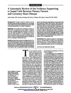
Initially, the fabrication process allowed the creation of digital circuits in a small scale of integration. To make a better picture, the first microprocessors had less than 4000 transistors, while currently we are going through hundreds of million transistors in a die and looking forward to develop one-billion-transistor chips within the next years. So it is easy to understand that, in those early days, the focus of the research in the microelectronics field was on making the fabrication process better, intending to allow higher density of circuitry per chip. Restricted by such constraint, the complexity of the integrated circuits design was relatively low, accomplished by small teams using extremely simple design-aid tools mainly for physical layout edition. But nowadays, when it is possible to fabricate chips with hundreds of millions of transistors and to count on a marked demand for products with greater complexity every year, the design process has turned to be the bottleneck.
FIGURE 2.2 - The "Design Gap" [SIA99]
14
The "Design Gap" is how it is being called the increasing difference between the growth of the productivity of design engineers and the growth of the logic density allowed by the chip fabrication process. Figure shows a graph with actual numbers and estimations for the years to come. So as the need for productivity was getting more and more important, the development of efficient design methodologies had been the target of many research groups all over the world. This battle for productivity - which will probably never end - is discussed in the next section.
2.3 Integrated System Design Flow The process of the design of integrated systems comprehends the creation and transformation of different kinds of descriptions, using several domains and abstraction levels. To cope with the increasing productivity requirements, more levels, domains and transformations are added to the process. A design methodology can be understood as the systematic use of a set of transformations, from the initial description to the final system. Some of the transformations add new information to the system description, while others are aimed to verify the correctness of the description or extract from it information which weren’t explicitly there. The former type is usually called synthesis while the latter, analysis. In Figure 2.3, a typical design flow is depicted, showing the transformations between different kinds of descriptions.
2.3.1 Functional Specification and Validation The design usually starts in a very high level of abstraction, by describing the intended functionality of the system: - system-level specification [SAN00]. This description disregards every implementation detail, focusing only in the system behavior and its interactions with the external world. The system description can be done using one or more languages. The SystemC approach [SWA01], for instance, advocates for a single specification language, in order to ease the interoperation of design tools and reduce the costs of the design within the industry. In other hand, the TIMA research group [JER99] and the Ptolomy Project [LEE01] focus in the interoperation of languages and modeling styles. Other approaches for system level design include Ocapi [DES00], SpecC [GAJ00], SDL [ELL97] and Forge [DAV01].
15
Some of the languages used for system specification have formal semantics, with underlying mathematical structure - e.g., Petri nets, finite state machines - while others derive from previously developed HDLs or programming languages. Visual languages and/or visual extensions for textual languages are also among the alternatives for system modeling. After the modeling step, a functional validation takes place. This is done by simulating or executing the system model, so that the functionality can be verified. No performance tests are executed on this phase, because no assumptions about the implementation were made yet. If the functional requirements of the system are not met, the model should be reviewed, otherwise the next step of the design flow - model partitioning - is started.
Functional Specification
Functional Simulation
Partitioning
Software Specification
Hardware Specification
Compilation
Synthesis
Co-simulation
Interface Synthesis
System Verification
FIGURE 2.3 - Simplified System Design Flow
2.3.2 Partitioning The partitioning problem can be defined as the mapping of the expected system functionality to the components which are expected to build the system. Examples of components in typical hardware/software systems are standard processors or microcontrollers - and the software to be executed on them -, custom ASIC chips, memories, busses, configurable logic. So, the partitioning procedure
16
takes as input a functional model of the system and separates the functions which are going to be implemented by each one of the components. It is important to notice that the procedure actually starts by the decision on which components will actually be part of the implemented system. This decision, obviously, strongly influences the partition itself. The concept of platform-based design [SAN00] was introduced in order to reduce the complexity of this task. According to this concept, the set of components which is used to build a system is strongly related to its application domain. So, by establishing a well defined set of components - a platform - and by validating it in a particular application type, it could be reused in future designs within such domain. By relying on already developed and validated platforms, the partitioning step can be done more easily, by mapping automatically the system functionality to the platform modules. Companies such as Coware [VAN00] and Cadence [CAD01] are known to support the concept of platforms. Besides the choice of the system components to which the functionality will be mapped, other key issues on the partitioning step must be highlighted: abstraction level of the functional specification (task level, behavioral level, etc.), granularity (amount and complexity of the functional units resulted by the decomposition of the functional specification) and the details about the partitioning algorithm itself (metrics of quality, cost function, solution space covering strategy, etc.) [BEC97].
2.3.3 Software and Hardware Specification, Simulation and Implementation Usually, a great amount of the system functionality is mapped into software during the partitioning step. [ARN00] states that up to 80% of a system is software running on a platform of general purpose or custom processors (CPU and/or DSP) tightly coupled with unique dedicated hardware. While the software part show more flexibility, allowing simpler error correction and upgrades, the part implemented in dedicated hardware has superior performance, so it is used for the time-critical functionality of the system. The software specification generated from the partitioned system description is usually programming language source code. When the platform where the software is going to run is pre-existent, there is usually available a compiler to generate object code, as well as a set of software drivers, so the software modules can access the dedicated hardware parts transparently. In most cases, a simulation engine is also available, so the software modules can be tested over a software emulation of the hardware platform. Minor corrections may be done directly in the generated source code, but major revisions should be done in the system model, so the partitioning can be re-done to ensure better results.
17
However, in most of the cases there is some customization in the underlying platform. This customization is defined by the hardware specification taken from the partitioned system description. It is usually HDL code, which should be simulated together with the software modules and its underlying platform. This procedure is called co-simulation. Again, minor corrections can be done directly in the HDL code, but if major corrections are necessary, it should be done in the system specification. Once the co-simulation shows the desired results, the synthesis of the hardware modules can start, as well as the synthesis of the communication structure that allows the interoperation of the hardware modules and the platform that runs the software part. Such synthesis is by itself very complex and will be described in details in subsection 2.3.3.1. Once the customization of the underlying platform is done, it is necessary to ensure that the software modules would be able to run optimally over it. New drivers must be implemented, to make the bridge between the software modules and the customized hardware, and - if the software processing hardware was also customized - new compilers must be generated.
2.3.3.1 Hardware Synthesis The synthesis of the hardware modules and the communication circuitry is a very complex task by itself. After the system partition and communication generation, those modules are described in a high level of abstraction using a HDL. In order to translate such abstract description into actual hardware, a set of model transformations must be done. Such process, depicted in Figure 2.4, is based on techniques developed over more than three decades of research.
Behavioural Synthesis
Logical Synthesis
Physical Synthesis
Fabrication
FIGURE 2.4 - Hardware Synthesis
In the behavioral synthesis, the high level model of the hardware part decomposed in a three sub-models:
18
a sequence graph, which defines the operations that must be performed by the circuitry, as well as the order that the operations should be executed; a set of functional resources - usually a library of functional blocks which are available for the implementation of the circuitry; set of design constraints, which specify limits - for size, performance, power consumption, etc. - that should be respected by the final implementation. The behavioral synthesis comprehends three stages. In the first stage, each operation on the sequence graph is scheduled, respecting the dependencies among them. Once the schedule is done, each operation must be assigned to a functional block. To minimize area, each functional block must perform several nonconcurrent operations. So, in the second stage the resource sharing is optimized so that a minimum number of functional blocks can be found, still respecting the schedule previously done. Finally, the third stage - resource allocation - can be done, by explicitly assigning each operation to a functional block. Following the synthesis flow, the next transformation - called logic synthesis - has as main goal the generation of a logic description of the circuit. The logic description - a net of logic gates, which are modeled as a set of boolean equations - is necessary for the physical synthesis later on. Furthermore, several techniques can be applied during the logic synthesis in order to reduce the complexity of the final circuit, by reducing area and power consumption or even easing the testability. Finally, the physical synthesis has the responsibility on the generation of the physical layout of the circuit. Usually, this is done by mapping each logic block - resulting from the logic synthesis - into pre-defined layout cells. Such cells are usually grouped in a library, possibly with alternatives for each cell - tailored for smaller area, higher performance, lower power consumption, etc. The libraries are closely related to the circuit fabrication process, so after this stage should probably not possible to change the circuit fabrication technology. After the technology mapping, the relative position of the layout cells is then defined, and the layout of the connections among them - and the external world - are generated, following the connection between the blocks in the logic netlist in a procedure called Place-and-Route. Very complex algorithms are used in this stage, in order to minimize the number and the length of the connections, because such factors affect significantly the circuit performance. Once the cells are placed and routed, the circuit is ready to go for fabrication.
19
3 Design Automation Tools 3.1 Introduction As shown in Section 2, the design of integrated systems is complex, requiring a great amount of automation in order to be done. The automation of the design tasks - usually known as CAD (Computer-Aided Design) - is performed by specialized software running over general purpose computers. In some specific design automation tasks, however, specialized hardware can be required, such as highperformance computers used for simulation or configurable platforms used in emulation. But in most of the design flow, the design automation comprehends the transformation of high level design representation into optimized equivalent lower level design representation. The design process starts with the capture of the initial specification. Such specification can be done in any of the design abstraction layers described in Section 2: functional, behavioral, logic or even physical. No matter in which layer of abstraction the design entry is done, some verification must be done to ensure the correction of the design model, followed by synthesis procedures, in order to transform the design model into an equivalent model in a lower level of abstraction. In order to assist the designer on each of the steps, a variety of design tools is needed. The next subsections detail such tools, grouped by functionality: design entry, simulation, synthesis and verification.
3.2 Tools for Design Entry and Edition Design entry and edition tools are those allowing the user to create or update the design specification. Such specification could be the entry point of the design flow, as well as an intermediate format, generated automatically by one of the synthesis tools within the flow. Such tools are of great importance, because the designer rely completely in them when it comes to translate the initial idea of a product into an actual design specification. Furthermore, such tools also have the task of translate the internal formats used by the synthesis, simulation and verification tools into visual information, easily understandable by the designer. In the following subsections, the most important design entry and edition tools are analyzed.
20
3.2.1 Schematic Editors Also called Block Editors or Diagram Editors, such tools present the design as a network of interconnected blocks. Such blocks and connections can model a variety of design elements in various abstraction levels: electric diagrams, where the blocks are transistors, resistors, capacitors, etc. ; logic diagrams, where the blocks are logic gates; structural diagrams, where the blocks are complex modules, such as decoders, filters, buses, etc.; functional diagrams, where the blocks are descriptions of the system functionality. In the first three types of diagrams, the connections between the blocks represent mainly the electrical connections, while in the functional diagram they can have other semantics to make possible functional decomposition. In order to better organize the design information, most schematic editors use hierarchy when displaying the schematics. This technique is based on the encapsulation of a set of interconnected and related blocks into a single one, and only its interface is displayed. When the designer needs to view or edit the contents of the complex block, then it is displayed. This feature is also helpful when a group of designers work over a particular design, because they can have a top hierarchy view of the system, and through that view they can better understand how the block they are working on interact with the modules developed by the colleagues.
3.2.2 Layout Editors The main function of layout editors is to visualize and allow the edition of the circuit layout information - the set of masks which are send to the fabrication process, each one corresponding to a particular layer of the circuit structure. While critical in the early years of electronic CAD, when most of the layout was created by hand, layout editors are auxiliary tools in the current design flows because in most of the cases the layout information is automatically generated or taken from pre-defined cell libraries. The direct edition of the layout information doesn’t occur often, and is restricted to small corrections of the automatically created layout. However, in niches where the automation of the design has not yet achieved a high level of sophistication - for instance in integrated systems composed by mixed digital-analog modules or MEMS - the use of layout editors is still critical.
21
FIGURE 3.1 - Schematic editor screen snapshot
FIGURE 3.2 - Layout editor screen snapshot
22
3.2.3 HDL Editors The use of HDLs, introduced in the 1980s, added the possibility of textual design entry. While many designers were used to the graphical entry through layout or schematic editors, a large group of them was already proficient in programming languages, so the impact was not significant. In the beginning, the tools used to support HDL design entry were simple text editors. Further resources were added - such as syntax correction, keyword coloring, library cross-references - but they were not significantly different from those found in software development environments. Integrated approaches - with both textual and graphical design entry also became available. In such tools, the interface of a block could be graphically described, and the HDL code for it would be generated. The other way was also possible in some of them, so that the tool would parse the HDL files and generate block diagrams showing the interconnections and hierarchical relationships among design blocks.
FIGURE 3.3 - HDL editor screen snapshot
23
3.3 Simulation tools Simulation tools provide models and execution platforms to analyze the systems response to a series of stimuli applied to its inputs. By doing so, the designer can have an outlook on the system functionality and performance prior to its implementation. This is a critical issue in integrated systems, because the fabrication costs involved are very high, and organizations can’t bear the costs of the implementation of badly designed systems. The simulation step is iterative, allowing the experimentation over the design solution space. There are specific tools for each step of the design flow, related to each level of abstraction: functional and behavioral simulation – in the highest abstraction level, the functionality of the system is experimented. Usually the simulation model doesn’t have any implementation-related information. Some constraints such as performance, area and power consumption therefore cannot be taken into account; logic simulation – the simulation model is built as a set of boolean equations, so the simulation is done by applying vectors of input values to the equations, and then comparing the equation results with the expected values for output. If the logic netlist is associated with information from the place and route steps – for instance in FPGA or standard cell designs - information about clock operation frequency and power consumption can be already estimated;
FIGURE 3.4 – Graphical Visualization of Logic Simulation Results
electrical simulations – this type of simulator uses algorithms which are based on the electrical models of the system basic electrical components – transistors, capacitors, resistors, inductances. Due to
24
the complexity of the simulation computation, only small modules of the system are simulated at once. The simulation comprehends the calculation of the the waveforms on each of the circuits nets given an input stimulus. Accurate estimations regarding operation speed and power c#onsumption can be obtained.
FIGURE 3.5 – Graphical Visualization of Electrical Simulation Results
3.4 Synthesis tools Synthesis tools allow automatic translation from an abstraction level to a lower one. They are responsible for aggregating design data to the models, so they can describe the design with more details in a lower abstraction level. The synthesis tools can be divided in three groups – behavioral synthesis, logic synthesis and physical synthesis - where the models generated by one of them is input to the subsequent. The fundamental topics regarding synthesis tools were already discussed in section 2.3.3.1.
25
3.5 Verification and Test tools Verification tools are responsible for error detection in design models. They do so by comparing two different models – one of them considered correct, or golden as it is often referred to - and checking their equivalence, so if positive they would be both considered correct. The verification tools can be divided in two groups. The first group of tools check for equivalence between two intermediate models of the same system. If they are not equivalent, it means that errors were included during the design process – i.e. during synthesis. Examples of such tools are netlist comparators, logic equivalence checkers, electrical and logic extractors. The second group checks the consistency of a model against a set of rules. Such rules are defined in such a way they can denote a correct design. Examples of such tools are design rule checkers and electrical rule checkers. Testing tools are responsible for the validation of a completed design. They support evaluation of the fabricated circuit, in order to check whether the implementation of a design is coherent to its initial specification. The following strategies are well known and widely used for testing purposes: test vector generation – in order to provide testing information to the fabrication units, many design tools provide test vectors – sets of input data and related expected output data – so the systems can be testet in a black-box manner right after fabrication; boundary scan – the testability of a system can be improved if special structures are included in the implemented systems to allow them to be observerd and controlled from the outside. Boundary-scan is a standard for control and test signals that are included in the systems, so they can operate in two modes – normal and scan – and their internals can be verified in more details after the fabrication; BIST – built-in-self-test is another concept used to include testing structures inside a fabricated system. In this case, the need for external testing equipment is minimum if compared to the two previously described approaches. All the test vector generation and output analysis is done internally – simpler and faster. The results can be already analyzed internally, and only highly significant results are sent to the external analysis.
26
4 Design Automation Frameworks 4.1 Introduction A Design Automation Framework is a software environment which aims to support CAD tool developers, CAD administrators/integrators and designers [BAR92]. It provides automatic execution to some of the time consuming tasks performed by each of the three types of users, reducing the complexity of the design and increasing the productivity. So, a CAD Framework should provide mechanisms to support tool development, tool integration and intercommunication, as well as to allow a simple and flexible usage of those tools.
4.2 EDA Frameworks: The Classic Concept Figure 4.1 shows the classic structure of a CAD Framework as proposed by [BAR92]. As one can easily notice, the system comprehends a number of abstraction layers built over the operating system of the designer’s workstation. It was designed to hide from the designer the underlying complexity of the design automation software - only the tool developers and administrators would have access to the lower layers. In the following subsections, the classic structure of a CAD Framework is analyzed in details. The functionality of each module is reviewed and the most significant advances obtained from the usage of such module is highlighted.
4.2.1 Operating System Services The functionality of the design framework is based on the operating system foundations. Among the services of the operating system which the framework relies on are: File Services, for data organization and management; Process Services, for concurrent multi-program execution; Network Services, for communication with processes and systems executed in different workstations; User I/O Services, for the communication with the user and other peripheral devices.
27
It is not reasonable to expect that every operating system could be able to provide the same services, so an interface layer between the framework and the operating system is needed. Such interface offers to the framework a set of standard operations and maps it to the particular services offered by the host operating system. Basically, such operations involve physical data management and process management activities. Using such approach, the details of the particular operating system are hidden from the designers and tool developers, which should be able to deal with the framework regardless of the operating system on which it is running. In most cases, however, this feature could not be fully achieved, in despite of the efforts of framework developers and administrators.
FIGURA 4.1 - Framework classic architecture [BAR92]
28
4.2.2 Process Management Services The processes which allow the execution multiple tools and data repositories concurrently in a single machine - and possibly in multiple computers in a network - should be managed properly within the framework. Modern operating systems already offer some of the facilities needed for such management: network file systems, standard resource locators, support for concurrent process, etc. However, some services should be customized to the needs of a CAD framework, for instance a load balancing system, in order to distribute among the machines of the network the processing load needed by particularly costly tasks [SCU95].
4.2.3 Tool Management Services Tool developers and administrators need to be supported by the framework in the tasks of tool integration. The following resources should be designed to offer such support: User Interface Services, which offers facilities for the construction of user interfaces to the integrated tools; Data Management Services, which organize the design data and provide access authentication; Data Representation Services, which organize the relationships among the various blocks of design data. Version Services, which support the consistent evolution of the design by introducing checkpoints and managing different versions - often this facility is provided by the design management services. Such facilities provide data-driven integration among the design tools, once the tools were developed over the framework foundation. The following subsections detail each one of them. Tools which were developed to other systems or applications can also be integrated through a foreign tool interface. Such interface is necessary to grant the compatibility within the framework, because the tools should be able to exchange data in a standard way, no matter if they are implemented specifically to the framework or not. This issue is cover in more detail in subsection 4.2.5.
4.2.3.1 Data Representation and Management Services Due to the low complexity and small amount of the design data, the first generation of design automation frameworks didn’t have specific facilities for data management.
29
As the complexity of the systems to be designed grew, binary and textual data structures were created - usually binded to a particular tool - in order to represent specific steps on the design flow, such as layout descriptions and logic schematics. Since many design tools were implemented separately, by different teams or vendors, several data formats were created. To grant its interoperability, data format conversion tools were widely used and every design environment integrating a number of design tools was already distributed with a set of translators. With the increase of the number of tools needed in the design flow, as well as the evolution of the data formats, resulting in several versions for each one, the implementation and maintenance cost of a set of translators become to high. The first solution to be proposed was the adoption of standardized exchange formats, which should be understood by every tool - each tool would have its own format translator internally, performing the conversion of the standard format into its own internal data representation. Languages such as CIF (Caltech Intermediate Format) [SHE93], EDIF (Electronic Design Interchange Format) [ELE00] or even VHDL and Verilog are examples of widely used tool exchange formats. Later on, more complex issues arose and the data management for concurrent designers became one of the main problems to be solved within the design automation frameworks. Version management, active references from every design entity to each one of its instances (if the entity is edited, how to propagate the change to the instances), data consistency control for forced interruptions in the design process, access control for concurrent edition over a particular design entity are among the issues which were being researched more recently in this field.
4.2.3.2 Data Versioning A design data versioning service can be considered as specialization of the data management service, because it deals with the management of multiple sets of design data produced as several alternatives for a design transformation. On the other hand, it can be considered as a supporting technology to the design management services, because it supports the design team through its navigation over the design solution space. The main functionality expected from a versioning service include: the maintenance of multiple alternative solutions for a particular design problem, postponing for a later time the decision on which one would be implemented in the final design; the possibility to navigate backwards in the design history, so a previous state of the design can be restored and/or analyzed – such feature is essential when a wrong design decision was performed, or
30
when the access to the situation from which the current design was derived is needed. Several versioning strategies can be found in the literature. Some of them organize the versions in a linear fashion, allowing only multiple alternatives on the most recent versions. Some approaches are more powerful, allowing multiple alternatives for all of the versions of the design by modeling the version history as a tree or acyclic graph. Comprehensive reviews on the subject can be found in [KAT86, KAT91] and [WAG94].
4.2.3.3 User Interface Services The study and development of interfaces between user and computer applications have been done since the early days of computing, because the user productivity, satisfaction and efficiency often depend on the quality of such interface. However, the evolution of the services of interface between designers and frameworks was much slower than other framework services describer earlier in this text, such as data representation and management. This situation is due to the limitations of the visualization devices available at the time of the introduction of the design frameworks. In the beginning, the graphical capabilities of the displays were very limited, so the design process was almost completely done without direct manipulation of the design data. With the availability of graphical displays, graphic manipulation of the design data was done by specialized personnel, working only in this particular task, because the costs to provide graphical workstations for the engineering personnel was too high. Once the costs were bearable, and the techniques for implementing graphical user interfaces were refined - pointer devices, windows, menus, buttons, etc. - the designers started to work directly on the design. Initially, the ability to interact graphically with the design data was mainly used to physical layout visualization and edition. Efficient data structures and algorithms were developed to allow the fast navigation and edition over very large sets of layout data [SHE93, TRI90]. As the levels of abstraction in the design activity were raised, the design visualization through interconnected block diagrams was widely used, both for logic-level schematics and for structural design based in HDLs. Besides making easier the manipulation of the design data, the graphical interfaces helped also in design management: documentation, project management, communication among designers, etc.
31
4.2.4 Design and Methodology Management Services Design and methodology management tools are often called meta-tools, because they don’t deal directly with design data itself but support the designer interaction with the design data and tools. The multiple tools needed by the designer during the design process are often organized in a so-called design flow. The tools that manage the design flow of an integrated circuit are responsible for the correct sequence of steps taken by the designer while going from the initial specification to the final implementation. The basic approach was based on sequences of automatic tool invocation, which were supposed to support each of the tasks performed by the designer. Besides that, the design flow management should also take care of the storage of the different visions of the design data, produced and consumed by each tool. One of the first problems to arise when design flow management systems were introduced was the need for flexibility on the flow automation. Such flexibility is needed because the design steps and tools are constantly being updated, due to the increase of the complexity of the designs and, as consequence, the improvement of the CAD techniques. The design flow modeling should be as generic as possible [KWE95], so it can be adapted easily to face the evolution of the design methodologies and tools. The creation of generic design flows was often based on the association of design tasks and automation tools. Such approach saved the designers from the tool invocation and the data transfer from one tool to another - format conversions could be also be done automatically when needed. As advantages, the process of design would be straightforward and faster. Furthermore, it would be performed in a standardized way, making easier the communication and design data exchange among members of a design team (or even the replacement of one of them), once all of them would be following similar design procedures. In opposition to the benefits, a set of issues had to be solved or optimized by design flow management tool designers [JAC95, BOS95, WAG94, BRE95]: design methodology modeling, so the management of the design flow can follow pre-defined, well known methodologies and styles; multi-user design flow, when the design tasks are performed by several designers, so the interdependencies among tasks should be handled properly; facilities for the storage of milestones, from which the design can be continued in multiple flows, allowing alternative implementations for the same design, for the sake of comparison; design metrics evaluation, in order to support the analysis of the project status, productivity evaluation, quality of the design, etc.
32
The problems which are dealt by process management tools in integrated systems design are generic, shared by many CAD environments from other engineering disciplines. In spite of that, few technological advances have been shared by them, and process management services have been developed individually for each domain.
4.2.5 Tool Integration and Encapsulation Services Design tools can be incorporated to the design environment in several ways. Usually, we can classify them all in two groups: encapsulation and integration. The main difference is the degree of exposure of the tool internals to the framework. In the encapsulation, the framework has no access to the tool functionality, so it communicates with it only by data exchange. This approach is also called black-box integration or foreign tool interface. In the other hand, the integration of a tool requires direct access by the framework to its internal structures - i.e. function calls, APIs, etc. - and is also called white-box integration. While the encapsulation can be done in nearly any type of tool, the integration assumes that the need for communication structures was predicted during the implementation of the tool, or that the source code is available for the implementation of such structures. The management of the integration and encapsulation of tools comprehends the characterization and the control of such tools. For a small set of tools, the designer can manage the characterization herself, but for complex frameworks, the amount of information to be managed is very large: tool name; tool version; physical storage of the tools executable and configuration files; online documentation; initialization procedure; runtime environment or shell; computational resources needed; input and output data formats; data repository configuration. If those features are available to the design environment, it can automate the execution and data exchange for every incorporated tool, providing the designer with a single interface to control them all in simple manner. So, both integrated and encapsulated tools can be accessed transparently by the designer.
33
4.3 Evolution of EDA Frameworks In the recent years, the concept of design automation framework has been revisited, due to several reasons. Some of the disadvantages and limitations of the previous approach could be solved, but new challenges also arose. The following subsections review some of the limitations of the frameworks which were build over the classic concepts detailed in the previous section. It also presents some advances on computer science and engineering disciplines that provided the framework developers with tools to overcome some of those limitations. Finally, some frameworks which are using such technologies are reported.
4.3.1 Dependency to the Operating System The classic definition of design frameworks came from the natural evolution of the design-aid tools and the needs on their interoperation. While such approach can be considered straightforward and of simple implementation, its ad-hoc nature restricted the possibilities of adaptation to newer environments and incorporation of newer technologies. When of the introduction of the framework concept, in most of the cases the Unix operating system was the platform which supported the CAD tools executed on the designers workstations. So, most of the frameworks were built over such platform. In the 90’s, however, the ratio between processing power and cost started to point the increasing advantages of the PCs - based on the Windows operating system - as CAD workstations. As initially proposed, the design frameworks were supposed to be portable to different operating systems, once they were built over a layer of operating system services, which could hide the differences among the operating systems and grant transparent execution over any of them. However, due to a number of reasons the theory could not be translated into practice easily. In order to gain performance, many tool and framework developers relied on direct access to operating system resources instead of using the operating system services layer. By bypassing that layer, the platform independence was compromised, demanding significant effort on the porting to other operating systems. As a result, only a few tools and frameworks could be ported to Windows workstations, and in many cases the tools and frameworks had to be rewritten almost entirely. Other side effects of the dependency of the framework to the operating system can be noticed: foreign tool interface definition didn’t regarded the invocation of tools running in different machines with different operating systems, as well as access to data stored in different file systems;
34
remote procedure calls were mostly platform dependent, so the tools and frameworks which relied on those techniques were more difficult to port; platform independent libraries for user interface such as Motif were only partially successful, due to compatibility reasons.
4.3.2 Configuration of the EDA Market The initial research and development of design frameworks was backed by governmental and industrial funding. It was expected that the commercial success of the first generation of frameworks would support the evolution of the framework development techniques, enabling the designers to cope with the increase of the design complexity. However, the configuration of the EDA market followed a "besttool-of-the-class" direction: designers preferred to use individual and specialized tools from a variety of vendors instead of using a complete solution from a single vendor, because no single vendor could provide the best tool for each step of the design flow. Furthermore, the design houses also decided not to rely completely on a single CAD framework vendor due to strategic reasons: the design house would depend too much on the CAD vendor. If the framework vendor raised the tools license fees, were unable to provide a particular tool or even went out of the market, high costs would incur to the design house, affecting specially the product time to market. Several entities, such as the CAD Framework Initiative [FID90] and the Silicon Integration Initiative [SII02], tried to establish standards for multi-vendor design frameworks, but their efforts were not successful. The lack of commercial success of the design frameworks caused the reduction of the research and development in the field. Without financial results to back the further development, only a few research groups remained active. This situation only started to change when some advances in software engineering techniques were found suitable to solve some of the problems found in the first generation of design frameworks. The evolution found in the development of design frameworks for other disciplines, such as in mechanical, chemical and architectural design, also motivated the analysis of possible application on EDA. The next session review some of those technological advances.
35
5 Engineering techniques applied to framework structural development 5.1 Expert Systems The fundamental concept of expert systems, sometimes referred as knowledge-based systems, relies on the assumption that the knowledge related to a particular topic can be stored in a computer system in such a way that knowledge pieces can be combined and retrieved in order to solve a given problem [ENG93]. Such systems were initially developed to assist decision-makers in a corporate environment, so that the knowledge taken from a group of experts in a particular field could be preserved in a knowledge base and utilized when needed. The structure of an expert system is depicted in Figure 5.1:
Knowledge Base User Interface
Agenda Inference Engine Working Memory
FIGURE 5.1 - Expert System basic structure
The knowledge base contain all the rules and most of the facts stored by the system. Each rule comprehend a relationship of cause and consequence: antecedent => consequent, or if => then. The inference engine controls the overall execution of the rules. It searches through the knowledge base, attempting to pattern match facts or knowledge present in memory to the antecedents of rules. If a rule’s antecedent is satisfied, the rule is ready to fire and is placed in the agenda. When a rule is ready to fire it means that since the antecedent is satisfied, the consequent can be executed.
36
In EDA, knowledge-based systems have been used in academic design environments to help the designers on the solution space navigation. The Ulysses framework [BUS89] was among the first design environments to integrate a knowledge base to support task execution and methodology management. Such knowledge base was intended to behave as an intelligent assistant to the designer, providing information about how to reach the design goals by supporting the scheduling of design tasks and offering details on CAD tool operation. Such approach intended to abstract from the designer the workflow model, in opposition to the approaches described in Section 6.2, where the designer explicitly defines the workflow model. The Odyssey Design Environment [BRO92] also offers such guidance through its Minerva module. It intends to support design planning by offering to the designer the possibility to state the design constraints in a so-called problem level. At this level, the designer can carry out design directly in terms of statements such us “synthesize an operational amplifier to meet a set of specifications” or “verify the performance of an ALU”, rather than choosing specific tasks to achieve the desired goals. The plans created by the Minerva module are then modeled as a workflow by the Hercules and Cyclops modules. In opposition to Ulysses, Odyssey provides full support to user-defined workflow models [BRO92a]. Other frameworks are known to have used expert systems and knowledge-based systems. Many of them are referenced in [HAR90], which also state a possible reason for the non-adoption of such approaches in commercial CAD environments: knowledge-based design planning often divide the solution on a large number of small design transformations, performed by small, highly specialized tools, while commercial CAD systems are usually built as a smaller set of powerful tools.
5.2 Object Orientation Object-oriented techniques were proposed in the 1980's within the software engineering and programming language communities [PRS96]. Such techniques advocated on software reuse through the application of information-hiding concepts, so a software system can be developed as a set of self-contained modules interacting among themselves by message passing. Actually, the main concepts which define the object-oriented paradigm - classes and objects, inheritance, encapsulation, polymorphism and dynamic binding – were developed since the late 1960's [HOL94]. However, it was during the last decade of the 20th century that it started to boost general purpose software development productivity [PRS96]. This delay may be understood if the following facts are taken into account: general-purpose software development tasks were relatively simple at the time of the introduction of the OO paradigm, mainly due to the simplicity of the hardware resources;
37
software maintenance – which greatly takes advantage on the OO features – wasn’t a critical task, once the team who built the software usually was the one to maintain it. In the second half of the 1980’s, a shortage of software developers was reported due to the high demand of application software, mainly because popularization of PCs. In order to increase the productivity, the object-oriented paradigm was taken of the shelf and started to be introduced in the software industry environment. This introduction was done based on several methodologies, proposed by several research groups [PRS94, JAC92, BOO91, RUM91]. Later, the most important methodologies were adapted and put together under the name of Unified Modeling Language (UML), standardized by the Object Management Group (OMG) [KOB99]. Within the CAD Frameworks community, there were two main reasons for the adoption of object-oriented techniques. The first motivation, as stated in [GUP89], is to accelerate the development process of CAD tools and ensure the satisfaction of the users. Using object-oriented techniques, it is easier to do incremental software development, so an early prototype can be provided to the future users and the feedback about it can be obtained during development time. Furthermore, the object oriented CAD systems are easier to maintain and upgrade, because each modification affects only some small, self-contained modules of the system. While the first motivation is also true for every object-oriented system, the second one is particularly related to the complex data models needed by CAD systems. In systems based in simple data models, sometimes the overhead due to the usage of object-oriented techniques exceeds the granted advantages, but when it comes to data models with complex relationships, the object-oriented data modeling and maintenance is much more effective. In [HEI87], some object-oriented modeling constructs are reviewed regarding their applicability to CAD data: relationships - object oriented data models are able to express a wide range of relationships between data blocks. Relationships such as ISA (relating object sub-types to their super-types), COMPONENT-OF (denoting aggregation of objects) and INSTANCE-OF (relating an instance to its type) can be found natively in some object oriented languages. Furthermore, user-defined relationships can be implemented in order to fulfill CAD-related needs, such as VERSION-OF and DERIVED-FROM; customizable constraints - record-oriented data models usually have very strict rules to ensure consistency, which has as consequence the rejection of any transaction that is not complying with the rules. In CAD data models, such policy may be sometimes inadequate, because in many cases the system should annotate the modifications and notify the users, rather than rejecting the transactions. By using
38
customizable consistency rules embedded in the object model, particular procedures can be used under different conditions, and particular actions can be taken based on the kind of failure or restriction violation; complex data types - objects can be modeled after complex entities from the application domain. Such entities are well defined by the encapsulation of their state and behavior. In record-oriented data models, such entities would be broken in many parts, relying on aggregation relationships to ensure their integrity, incoming into higher design and maintenance costs on the data model; abstraction - the abstraction mechanism relies on the information hiding concept: an external view of the objects are provided, but their internal details are not available to the external world. This approach encourages the decomposition of the modeling problems into independent sub-problems. Furthermore, it allows the management of multiple views of the design data, because some designers may want to deal only with higher abstraction levels while others would have to understand implementation details, and with an object-oriented model the design of such structure is straightforward. Several EDA research groups started to turn to object orientation since the late 1980’s to better organize the development of CAD frameworks and many advances were reported in the most important design automation conferences. Notable contributions were achieved by the NELSIS group, in the topics of object oriented data models [VAD88], concurrent access to object databases and versioning [WID88]. Also following a similar path, Katz et.al. developed the Version Server [KAT86] and Design Browser tools [GED88], pioneering the use of hypermedia-like search and navigation structures in a design database. In methodology support, the advances were achieved by Cadweld group [DAN89], which extended the Ulysses framework [BUS89] by modeling design tools as objects in a design flow. Many HDLs were also extended/created to support object-oriented constructs. While the analysis of OO HDLs is outside of the scope of this study, some design frameworks supported such languages, as can be seen in [CHU90], intending to achieve the same level of code reuse and reliability as reported by software developers.
5.3 Object-Oriented Frameworks In the modern software engineering domain, a framework is an architecture to build extensible and reusable object-oriented software systems. According to Johnson and Foote [JOH88], a framework is a set of classes that
39
embodies an abstract design for solutions to a family of related problems, and supports reuses at a larger granularity than classes. So a framework defines an efficient, proven software architecture to solve design problems in a particular application domain. The framework defines the global structure of the application, its division in classes and objects, the key responsibilities of each part, how the classes and objects cooperate and how the control sequence is implemented. It is important to notice that Johnson and Foote, as well as many other theorists in object-oriented design, advocate that the strength of a framework lies on its abstract nature. This means that the architecture of the object-oriented software system should be expressed in terms of abstract classes (classes which cannot generate objects). From this set of abstract classes, several implementations can be derived, by creating concrete subclasses from the abstract ones. So, those classes would inherit the abstract behavior defined in the framework, as so would do the objects instantiated from them. In [PRE94] such structural aspects are specially highlighted, and special attention is given to the framework usage through specialization in application building. According to the author, a framework comprehends a set of building blocks, some of them ready to use, some unfinished. The global architecture is pre-defined, and the construction of a new application usually is done by adapting the framework components to specific needs by implementing variables and methods in the classes and subclasses of the framework. In the design automation field, such frameworks can provide foundations to the development of data models, as well as primitives for the construction of design tools. Differently from the classic concept of frameworks, such foundations are not executables or libraries, but abstract guidelines, which must be followed during the implementation of the design models and tools, so the interoperability is granted.
5.4 Design Patterns Many of the architectural solutions used in the construction of a particular object-oriented framework can be also used in another, even if they are tailored to completely different application domains. According to [GAM95], such solutions should be documented in a proper way, so their usage could be made simpler and their reuse stimulated. A design pattern is, then, a well-documented solution for a generic problem in software architecture. Such patterns are identified by names and included in catalogs, so they can be searched and referenced easily during the development process of software systems. The core of a design pattern includes [GAM00, GOL02]:
40
pattern name; motivation - problems it addresses; known uses - application scenarios, examples; structure: identification of classes and instances involved in the pattern; roles and responsibilities of each class/instance; types of collaboration among instances; expected advantages and costs due to the pattern usage. In the following subsections, we include some of the patterns included in the catalog by [GAM00], and we identify some known uses of them in EDA Frameworks.
5.4.1 Observer Intent: Define a one-to-many dependency between objects so that when one object changes state, all its dependents are notified and updated automatically. Motivation: A common side-effect of partitioning a system into a collection of cooperating classes is the need to maintain consistency between related objects. If the consistency is achieved by making the classes tightly coupled, their reusability is substantially reduced. This pattern organizes a loosely coupled approach for consistency maintenance. Application Scenarios: Many graphical user interface toolkits separate the presentational aspects of the user interface from the underlying application data. Classes defining application data and presentations can be reused independently. They can work together, too. Both a spreadsheet object and bar chart object can depict information in the same application data object using different presentations. The spreadsheet and the bar chart don’t know about each other, thereby letting you reuse only the one you need. But they behave as though they do. When the user changes the information in the spreadsheet, the bar chart reflects the changes immediately, and vice versa. This behavior implies that the spreadsheet and bar chart are dependent on the data object and therefore should be notified of any change in its state. And there’s no reason to limit the number of dependent objects to two; there may be any number of different user interfaces to the same data.
41
FIGURE 5.2 - Observers and Subject [GAM95]
Structure: The Observer pattern describes how to establish the relationships among the participating objects. The key objects in this pattern are subject and observer. A subject may have any number of dependent observers. All observers are notified whenever the subject undergoes a change in state. In response, each observer will query the subject to synchronize its state with the subject’s state.
FIGURE 5.3 - UML representation of the Observer design pattern structure [GAM95]
Participants: Subject •
knows its observers. Any number of Observer objects may observe a subject;
•
provides an interface for attaching and detaching Observer objects;
42
Observer •
defines an updating interface for objects that should be notified of changes in a subject;
ConcreteSubject •
stores state of interest to ConcreteObserver objects;
•
sends a notification to its observers when its state changes;
ConcreteObserver •
maintains a reference to a ConcreteSubject object;
•
stores state that should stay consistent with the subject’s;
•
implements the Observer updating interface to keep its state consistent with the subject’s.
Collaborations: ConcreteSubject notifies its observers whenever a change occurs that could make its observers’ state inconsistent with its own. After being informed of a change in the concrete subject, a ConcreteObserver object may query the subject for information. ConcreteObserver uses this information to reconcile its state with that of the subject.
FIGURE 5.4 - UML representation of the collaborations on the Observer design pattern [GAM95]
Known uses: The first and perhaps best-known example of the Observer pattern appears in the Smalltalk Model/View/Controller (MVC), the user interface framework in the Smalltalk environment [KRA88]. This framework advocates for the separation of the software functions: (1) that represent and store data (Model), (2) that allow the visualization of this data by the user (View) and (3) that capture the interaction of the user with both the data and its
43
visualization (Controller). MVC’s Model class plays the role of Subject, while View is the base class for observers. Applications on EDA Frameworks: In [GIR87], the development of a design environment built over the Smalltalk MVC framework is reported. The separation between data and visualization was implemented, so different representation formats of the design data could be presented to the designer. The design environment prototype, named STEM, had views for displaying layout information, spice models, EDIF code, among others, for every cell model in the design library. A controller was also implemented to allow the edition of the cells. Diva [GIG02], a framework for information visualization developed as support for WELD [NEW99] and Ptolemy II [LEE01] design environments, also relies on the separation of model and views and uses an Observer pattern to keep the consistency.
5.4.2 Composite Intent: Compose objects into tree structures to represent part-whole hierarchies. Composite lets clients treat individual objects and compositions of objects uniformly. Motivation: Graphics applications like drawing editors and schematic capture systems let users build complex diagrams out of simple components. The user can group components to form larger components, which in turn can be grouped to form still larger components. A simple implementation could define classes for graphical primitives such as Text and Lines plus other classes that act as containers for these primitives. But there’s a problem with this approach: Code that uses these classes must treat primitive and container objects differently, even if most of the time the user treats them identically. Having to distinguish these objects makes the application more complex. The Composite pattern describes how to use recursive composition so that clients don’t have to make this distinction. Application Scenarios: The Composite pattern should be used when part-whole hierarchies of objects should be represented, and/or when the difference between compositions of objects and individual objects should be ignored. Clients will treat all objects in the composite structure uniformly. Structure: The key to the Composite pattern is an abstract class that represents both primitives and their containers.
44
FIGURE 5.5 - UML representation of the Composite design pattern structure [GAM95]
Participants: Component •
declares the interface for objects in the composition;
•
implements default behavior for the interface common to all classes, as appropriate;
•
declares an interface for accessing and managing its child components;
•
defines an interface for accessing a component’s parent in the recursive structure, and implements it if that’s appropriate (optional).
Leaf •
represents leaf objects in the composition. A leaf has no children;
•
defines behavior for primitive objects in the composition;
Composite •
defines behavior for components having children;
•
stores child components;
•
implements child-related operations in the Component interface.
Client •
manipulates objects in the composition through the Component interface.
Collaborations: Clients use the Component class interface to interact with objects in the composite structure. If the recipient is a Leaf, then the request is handled directly. If the recipient is a Composite, then it usually forwards requests to its child components, possibly performing additional operations before and/or after forwarding.
45
Known uses: Examples of the Composite pattern can be found in almost all object-oriented systems. The original View class of Smalltalk Model/View/Controller [KRA88] was a Composite, and nearly every user interface toolkit or framework has followed in its steps. Applications on EDA Frameworks: Many hierarchical data models used in EDA Frameworks use, explicitly or not, the Composite pattern. Reported implementations can be found in [BRI01, EPS00].
5.4.3 Flyweight Intent: to use sharing to support large numbers of fine-grained objects efficiently. Motivation: some applications could benefit from using objects throughout their design, but a naive implementation would be prohibitively expensive. For example, most document editor implementations have formatting and editing facilities that are modularized to some extent. Object-oriented document editors typically use objects to represent embedded elements. However, they usually stop short of using an object for each of the many finegrained embedded elements - such as characters in a text editor - even though doing so would promote flexibility at the finest levels in the application. Applicability: the Flyweight pattern’s effectiveness depends heavily on how and where it’s used. Apply the Flyweight pattern when all of the following are true: (1)an application uses a large number of objects; (2) storage costs are high because of the sheer quantity of objects; (3) most object state can be made extrinsic; (4) many groups of objects may be replaced by relatively few shared objects once extrinsic state is removed; (5) the application doesn’t depend on object identity since flyweight objects may be shared, identity tests will return true for conceptually distinct objects. Structure: the following class diagram (Figure 5.6) shows the structural relations among the Flyweight participant objects, while the object diagram in Figure 5.7 shows how flyweights are shared.
46
FIGURE 5.6 - UML representation of the Flyweight design pattern structure [GAM95]
FIGURE 5.7 - UML representation of the Flyweight object sharing scheme [GAM95]
Participants: Flyweight •
declares an interface through which flyweights can receive and act on extrinsic state.
ConcreteFlyweight (Character) •
implements the Flyweight interface and adds storage for intrinsic state, if any. A ConcreteFlyweight object must be sharable. Any state it stores must be intrinsic; that is, it must be independent of the ConcreteFlyweight object’s context.
47
UnsharedConcreteFlyweight (Row, Column) •
not all Flyweight subclasses need to be shared. The Flyweight interface enables sharing; it doesn’t enforce it. It’s common for UnsharedConcreteFlyweight objects to have ConcreteFlyweight objects as children at some level in the flyweight object structure (as the Row and Column classes have).
FlyweightFactory •
creates and manages flyweight objects.
•
ensures that flyweights are shared properly. When a client requests a flyweight, the FlyweightFactory object supplies an existing instance or creates one, if none exists.
Client •
maintains a reference to flyweight(s).
•
computes or stores the extrinsic state of flyweight(s).
Collaborations: state that a flyweight needs to function must be characterized as either intrinsic or extrinsic. Intrinsic state is stored in the ConcreteFlyweight object; extrinsic state is stored or computed by Client objects. Clients pass this state to the flyweight when they invoke its operations. Clients should not instantiate ConcreteFlyweights directly. Clients must obtain ConcreteFlyweight objects exclusively from the FlyweightFactory object to ensure they are shared properly. Applications on EDA Frameworks: Flyweights can be applied to model the instance-of relationship, which is often found in design data models ranging from layout to high-level block diagrams. Instead of modeling the contents of each instantiation of a particular library block, a Flyweight can be used to refer each instance to a Flyweight pool where all the library data is stored.
5.5 Platform Neutrality As stated before in subsection 4.3.1, the independence from the underlying hardware/software platform was a critical point on the need for evolution of the CAD Framework concept. While this could not be completely achieved by the EDA researchers alone, some of the technologies developed in the field of programming languages are currently being used to address this issue. The Java technology, introduced in the mid 1990’s, presented a successful approach to platform independence by relying on runtime environments to
48
hide the underlying platform. Such runtime environments, known as Java Virtual Machine (JVM), are available for a wide range of hardware platforms, allowing programs written in Java language to be executed without changes in all of them (Figure 5.8).
-DYD
-DYD
-DYD
-90�IRU 8QL[
-90�IRU :LQGRZV
-90�IRU 3DOP
Unix Workstation
Windows Workstation
Palm Handheld
FIGURE 5.8 - Platform neutrality using Java Technology
Such execution model can be achieved by the joint use of compilation and interpretation techniques. Every Java program is built over an API of reusable object-oriented code, compiled to an intermediate format, called bytecodes, and organized in class files. Those class files are then interpreted during runtime by the Java Virtual Machine, and the bytecode instructions and data inside them are converted to the equivalent native ones for the target hardware platform where the Java program is being executed (Figure 5.9).
Java Source
Java API
Compiler Java class files Java Virtual Machine Target Platform FIGURE 5.9 - Layers in the Java execution procedure
Several approaches in the EDA field took advantage on the platform independence of the Java execution model. Several also were the critics against those approaches, since many predicted that the interpretation overhead of the Java execution engine would make it unusable for EDA tasks. The truth is that in many
49
cases the interpretation costs were not so significant, for instance in design entry and visualization tools, and the techniques used to improve the interpretation of Java bytecodes could achieve results comparable to native code execution in many applications. The first platform-independent CAD resources based on Java were design entry tools, usually embedded in webpages, aimed to allow web based design and education. The Cave Project [IND98], detailed in subsection 5.7.3, used Javawritten CAD tools for the design steps where high degree of interactivity with the user were expected. For the same purpose, the WELD Project [NEW99] created Java libraries for user interface, simulation and real-time modeling. In the Ptolemy project, a platform independent version of the suite of modeling and simulation tools was created, named Ptolemy II [LEE01]. The use of platform independent resources is particularly useful in the educational field, so there are fewer technical requirements regarding the student’s equipament needed to access the resources. Many educational frameworks were developed to support learning in a variety of topics, from basic semiconductor technology to digital design [WIE02]. Another design automation resource which relies on the Java technology is the JHDL [HUT02]. It comprehends a set of tools for FPGA design automation, supporting a design flow which starts from Java source code. All the design semantics are included in a set of packages, so no compilers or pre-processors are needed. The complete design and testbenches can be implemented as Java code, and the simulation/executed of the code can be done in an unified environment, which is also developed in Java. Design data visualization tools are also available as Java tools, so the complete environment can be executed in any platform where a JVM is available. An important advance in the concept behind the Java technology is the possibility of building platform independent distributed systems. Such possibility relies on the RMI technology - remote method invocation. This is a mechanism to allow objects running on different machines in a network to communicate. The mechanism is build over Internet protocols, so it can work in a heterogeneous network (composed by different kinds of computers). In JavaCAD [DAL00], this feature is explored to implement a distributed system for simulation of integrated systems composed by Intellectual Property (IP) cores. As shown in Figure 5.10, JavaCAD provides infrastructure for the distributed simulation of an integrated system, interconnecting the system designer and the providers of IP cores. This approach has the following advantages: the IP cores can be evaluated before licensing, because the designer can simulate his design together with the IP core without purchasing or even copying the IP content to his computer;
50
the intelectual property of the provider is not disclosed during the evaluation procedure, because the evaluating designer can access only the IP core functionality, not its implementation.
IP Provider
IP Provider
IP Core
IP Core
Designer Workstation
proxy object
proxy object
FIGURE 5.10 - Platform independent IP simulation
The implementation of the JavaCAD approach is based on the use of proxy objects, which are installed in the designer’s machine. During the simulation, such proxy objects - implemented using Java RMI - receive all the stimuli that the actual IP core should receive and forward through the network such stimuli to the provider’s server, where the IP content actually resides. The stimuli processing are done and the results are sent back to the proxy object, so it can feedback the system under simulation.
5.6 Multimedia The use of multiple ways for information visualization is called multimedia. Using such technique, the understanding of the information by the user is increased. Multimedia applications rely on at least some of the following formats: audio: sound effects, human voice, music; images: graphics, photos, diagrams; video: films, animations; virtual reality: interactive virtual worlds, navigational 3D graphics.
51
By using efficiently such resources, CAD environments improved the quality of the interaction between user and tools, providing on-the-tool training, active documentation, improved visualization and analysis of the design data. Multimedia based tools were reported to provide aid to designers and students in several key areas in the design automation field, such as signal integrity [DEL99], memories and registers [CHA99], logic design [SER99] and basic electronics [ZYS97]. In [IND97, IND01], [TOG01] and [MEM00] virtual reality techniques are used to allow 3D visualization of the layout information of integrated circuits and MEMS. In [OST01] that approach is extended, so the designer can visualize the layout information and simulate its behavior by toggling the voltage levels on the circuit structures.
5.7 Hypermedia Hypermedia can be defined as the capability to establish contextual connections among a set of data blocks. Its most known application is the World Wide Web (WWW), which is based in hyperdocuments built with the Hypertext Markup Language (HTML). A highlighted portion of the document can allow the access to another piece of related information – in the same document or in another one. Such technique make it easier the access to the information by allowing nonlinear navigation through distributed data repositories. Several researchers proposed hypermedia-based design environments, motivated by the construction and maintenance simplicity of such technology, as well as its acceptance by the users (a fact widely proved by the popularization of the WWW). Some of them are detailed in the following subsections:
5.7.1 Henry System In [SIL95], the Henry system was presented, defining the design environment as a client-server information system. Its goal was to support the distribution of the design data among network servers and the message-based interaction of the designers. While the project data was managed by the system, the design tools were not integrated, and the issues of methodology management, design management and user interface were not covered. The integration of foreign tools was predicted in the Henry system, but only as remote-executable non-interactive tasks. Figure 5.11 depicts the information flow on the Henry system. The client machine has access to the libraries and project data through hyperdocuments, which are processed in the locally installed tools. The client can also access the tools remotely installed, and the results processed by those tools are also formatted as hyperdocuments.
52
data server network message message
library server
client message
message
tool server
FIGURE 5.11 - Information flow on the Henry System
5.7.2 PPP System [BEN96] presented an approach for the integration of tools running in different servers, accessible through a single user interface. Such approach is based on the remote tool execution over the WWW. Comparing to the approach described in the previous subsection, the main difference is that in this case there are no tools installed in the client machine, so all the data processing is done on the server side. The design cycles in PPP are initialized by the designer, which requests to the web server the desired tool. The server replies with an hyperdocument, where the designer can input the necessary parameters and design data for the tool execution. The data is then sent to the server, which executes the tool and send the results back, also formatted as a hyperdocument. Since the results are displayed in a web browser, some data representation formats which are used in regular CAD tools - such as schematics, waveforms, layout masks, etc. - may not be supported. To allow such data to be visualized, the PPP system includes a conversion tool, which maps the unsupported formats into data which can be properly handled by the web browser. After the analysis of the results, the designer can repeat the procedure as many times as needed.
53
FIGURE 5.12 - Client-server architecture on PPP [BEN96]
5.7.3 Cave Project The Cave Project [IND98] is a research initiative aiming to make possible a user-transparent distribution of CAD resources over the World Wide Web. It can be divided in two parts. The first one, a framework of reusable software, available to design automation tool developers, allows an easier way to produce Internet-enabled design tools and model design data. The second one, a web based design environment prototype, validates the framework, and can be used for IC design and education. The original architecture of the Cave Project is based on the distribution of the design resources between client and server sides of the network, as well as on the interfacing of those tools using hyperdocuments. In order to define the design automation tools distribution over the network, the tools are divided in two groups, regarding the level of interaction of the designer with each tool. Interactive tools are attached to hyperdocuments and run inside a web browser on the client side, while non-interactive tools are executed on the server side, according to inputs from the designer on a HTML form. Group 1 - High level of interaction: this integration architecture is easily understood if related to the white box kind of integration. Belong to this group the tools with intense work of the designer over graphical interfaces, such as schematic editors and layout editors. These tools must be written (or re-written) using platform independent solutions, such as Java programming language, and be attached
54
to a hyperdocument. The execution procedure is described below and is illustrated on Figure 5.13: when the designer browser requests the tool hyperdocument through its URL, the server sends the hyperdocument with the tool attached to it; the client receives the application and executes it; the project data can be stored in the client or in the server storage systems (in the later, it is necessary to open another network connection). Group 2 - Low level of interaction: this integration architecture is easily understood if related to the black box kind of integration. Belong to this group the tools in which the user interface is based in data providing and analysis, form filling, simple choices over checkboxes and so on. Tools such as electrical simulators, rule checkers and automatic layout generators, which require only passing a circuit description file and some parameters, are typical examples of the low level of interaction tools. These tools run at a server machine and only exchange data with the client, using the Common Gateway Interface or Servlets. The execution procedure is described below and is illustrated on Figure 5.13:
when the user’s browser requests the tool hyperdocument through its URL, the server sends a HTML form, with the input fields related to the parameters required by the tool; the user fills the form and sends it to the server; the server starts the program, feeding it with the data provided by the user via form; after running the program, the server can send the results to the client and/or store locally. To avoid keeping network connections alive for a long time, the Group 2 integration architecture must provide methods to handle tools with long processing time. These methods may deal with push techniques. So, the server machine has to keep track of the client, while it is processing the data. When the job is finished, it opens a new connection to send the results. To keep track of the client, the server machine opens short time connections, by which it sends the current status of the job and receives acknowledgement from the client.
55
FIGURE 5.13 - Information Flow on Cave System
While achieving valuable results, as shown in [IND97] and [FRA00], such architecture was discontinued, as shown in [IND00], and a new model based on object-oriented concepts is currently the underlying technology on the Cave Framework.
56
6 Engineering techniques providing support for collaboration in design frameworks 6.1 Computer Supported Collaborative Work After realizing the lack of proper support to user-to-user interaction in multi-user computer systems, a group of software engineers and computer scientists created a discipline named Computer Supported Collaborative Work (CSCW) in order to study and research the dynamics of group work in a computational environment. Actually, CSCW should be seen as an interface among several disciplines [GRU94] including software engineering, databases, social psychology, human-computer interaction, distributed systems and cognition. Soon, another term was coined: Groupware. While interchangeable in many contexts, CSCW should be related to the knowledge area, while Groupware should refer to the systems which put the CSCW concepts into practice. The seminal paper by Ellis, Gibbs and Rein [ELI91] presents an excellent overview on those concepts. They highlight three aspects that should be addressed by groupware systems: communication, collaboration and coordination. The first aspect covers the medium used by the users to communicate. Much have changed since the publishing of the paper from Ellis et al. While they mentioned the dominance of asynchronous communication on computer environments, nowadays the use of internet telephony, chat systems and other synchronous communication tools is common. In the second aspect - collaboration - their focus is placed on the possibility of information sharing. Ellis pointed out that most of the research on multi-user systems directed its effort to insulate users from each other, for the sake of consistency maintenance. Finally, the third aspect - coordination - is regarded as an enhancer of the other two, as well as a necessary activity when a large group of people are supposed to accomplish a given task. In the following subsections, all the three aspects are revisited to allow better understanding about the CSCW area. Specific topics such as consistency maintenance and collaborative editing are detailed more carefully due to its relevance to collaborative design frameworks.
6.1.1 Groupware Taxonomy Groupware are usually classified according to its time/space characterization or to its application domain. The first taxonomy, described by Johansen in [JOA88], is shown on Table 1.
57
TABLE 1 - CSCW Time-space Taxonomy
Same Space Different Space
Same Time face-to-face interaction synchronous distributed interaction
Different Time asynchronous interaction asynchronous distributed interaction
This taxonomy regards the interaction spanning in time and space. Groupware tools and CSCW concepts can be applied to all the four possibilities shown in Table 1. In the same-time-same-space domain, CSCW only makes sense on supporting group communication and coordination, because the direct communication among the involved parties is possible. Examples of such tools include presentation panels, plenary voting tools and other meeting-room computer facilities. The samespace-different-time domain includes the communication and coordination tools for users taking shifts over the same computer infrastructure, for example in helpdesk facilities. In the same-time-different-space, some of the most challenging CSCW applications are being implemented, such as real-time edition of documents and internet-based communication (telephony, chat, multi-user virtual reality environments, etc.). In the different-time-different-space domain, email systems and asynchronous edition of documents are among the application examples. Other dimensions - such as group size (small groups, large groups), type of the task (coordination, planning, execution, etc.) and information format (audio, visual, text, etc.) - were proposed later, extending the 2x2 approach of the time/space taxonomy. The second taxonomy, regarding the application domain, is not absolute, because application domains can be created or merged as the technology evolves. The list above follows the items found in [ELI91] and [COL97]: messaging systems - this domain comprehends systems supporting asynchronous exchange of messages. Initially, the messages were textual, but other media have been used as well, such as voice, video and other application formats (embedded spreadsheets and databases, for instance). Besides providing the communication platform, such systems must also provide support to the users when dealing with the information they receive, in order to avoid the phenomenon known as information overload; multi-user editors - members of a group can jointly edit a document, and there are many ways to make it possible. This can be done synchronously or asynchronously. Each user must have some awareness of the others, but the awareness degree is case-dependent. There are also many options regarding the scheme for data sharing. In such a wide solution space lies the application domain of the multi-
58
user editors, and some of its challenges are going to be addressed in the following subsections; group decision support systems and electronic meeting rooms - group decision processes are known as time consuming. The goal of the applications within this domain is to speed-up and simplify the process by improving the quality of the resulting decisions; computer conferencing - this domain covers the field of synchronous communication, usually using audio and video. Recent approaches are being combined with messaging systems, so document exchange can also be done during conferencing. Formerly restricted to large organizations, operated in special rooms, conferencing techniques are available to desktop users by using internet streaming software; intelligent agents - not all the participants in a collaborative work platform must be people. Autonomous software agents can be implemented to perform specific roles within a collaborative software environment, interacting with the other participants when needed, and contributing for the group synergy; coordination systems - this application domain includes solutions to support groups in managing their diversity of solutions to the common problem. The applications can support a group leader on his/her tasks or even play the leader roll. They also support the members of the group on understanding their individual goals, how their goals contribute to the common goal and how they interact with the goals of the other members. In [ELI91], the coordination systems were divided in four groups: form, procedure, conversation and communication-structure oriented. Further analysis in this research field shows that the problem is not that simple, and that coordination should be done in many ways, combining domains such as communication, workflow (covered in Section 6.2), group decision and time-planning (group schedule and timetable, for instance).
6.1.2 Design and Implementation Issues Many of the issues on the design and implementation of collaborative systems are also found in other research areas. Actually, many of them have been addressed by the researchers on those areas exactly because of its relevance in the CSCW field. As the time/space taxonomy of CSCW points out, the groupware users are often distributed in time or space. Because of that, many of the issues on the design and implementation of such systems are covered by the research on distributed systems. Data consistency and fault tolerance in the case of network failure are among the topics researched within the distributed systems area that can be applied to groupware.
59
Other important research areas whose interests also overlap with those of CSCW are data communications and HCI (Human-Computer Interaction). Once the computer can be the only interaction medium between one user and the others, the facilities for supporting this interaction are critical to the success of the collaboration. In the following subsections, we detail some critical issues on the design and implementation of CSCW systems. Each of them is also covered by at least one of the forementioned research areas, so the extent of our coverage is limited by the applicability of the research results to groupware systems.
6.1.2.1 Data communication and storage infrastructure The need for efficient communication among the participants of a collaborative system is an issue that can rely on many of the advances on the research on data communication and networks: connectivity - several approaches on connecting nodes in a network, such as client-server, ad-hoc and p2p networks, among others, so the collaboration can take place in a dynamic environment, rather than be limited by a fixed network configuration; protocols - use of protocols tailored to the efficient transmission of the information in several formats, such as text, audio and video streams, so the collaboration can take advantage on multiple media for the communication; mobility - fast and low cost wireless communication platforms, so the collaboration is not restricted to the workstation. The data storage is also a critical issue, because two basic approaches are usually available: centralized or distributed storage. Each one has its pros and cons, and the decision between one or another should regard network latency, fault tolerance, consistency maintenance overhead and need for data replication.
6.1.2.2 User interfaces Interfaces to support groups of users differ from single-user interface, because they depict group activity and are controlled by multiple users rather than a single user. Thus, they introduce some design problems not presented by single-user interfaces. A basic problem is how to manage the complexity: multiple users can produce a higher level of activity and a greater degree of concurrency than single
60
users, and the interface must support this complex behavior. Other important issues regard whether or not the concepts developed for single-user interfaces can be applied to group interfaces. A common approach for implementing group interfaces is knows as WYSIWIS (What You See Is What I See) [STE87]. This implementation guarantees that the shared interface appears the same to all participants. Its advantages are the simplicity of the implementation and the strong sense of shared context - the participants can be sure that the others are seeing the consequences of his/her acts, and they can even reference elements by the position on the screen. Its main disadvantage is its inflexibility - there is no possibility of individual customizations of the interface, or embedded sessions of asynchronous work. Stefik et al. [STE87] have suggested that more flexibility can be obtained if the WYSIWIS concept is relaxed along four dimension: display space - the interface objects to which the WYSIWIS concept is applied; time of display - when the displays are synchronized; subgroup population - the set of participants involved or affected; congruence of view - the visual congruence of displayed information. The VNC tool (Virtual Network Computing) from AT&T Laboratories Cambridge is known as one of the most stable implementation of this technique, sharing the complete OS desktop. However, its implementation is tailored for pairs of users - one of them controlling the computer directly and the other one remotely. Other approaches have been researched in order to improve the quality of the group collaboration. The balance between user distraction and user awareness, for instance, is a critical issue and was already addressed by several groups [ELI91]. Such balance - which is application specific - should be carefully defined, so that each user can be aware of the actions performed by the rest of the group, but without being distracted from the tasks he/she have to perform. In one extreme, we have WYSIWIS interfaces: maximum awareness, once the actions of every user can be noticed by all of them, and the user distraction can be significant. In the other extreme, single-user interfaces, so there’s no distraction and no group awareness at all. Many techniques were proposed to set up a way between both extremes, such as reducing the size or changing the color of the elements being edited by other users. Figure 6.1 shows a snapshot of DOME [COK99], a collaborative text editor which uses background coloring to identify areas of the text edited by each user and font size change to identify which text areas are being currently being edited. Notice the fish-eye-lenseslike effect on the text, so the line under edition appears larger, and the text areas which are not under edition appear almost illegible.
61
FIGURE 6.1 - Snapshot of the DOME collaborative text editor [COK99]
6.1.2.3 Data granularity of the collaboration The smaller shareable data unit in a collaborative application – within this document referred as collaboration data granularity – influences both the application design and development, as well as the collaboration methodology. While many collaborative tools use the file as the smaller shareable unit, others reduced the granularity to allow users to share smaller units, such as lines and paragraphs in a text or individual objects or records in a database.
62
The main advantage of the first approach is its simplicity, because most of the concurrency control is implemented by the OS file system. Most of the users are also familiar with the file metaphor, so they can share it as they would share a document in the real world. However, many of the advantages of the computer support on collaborative work arise from the possibility of creating new methodologies which would not be feasible in the real world. As an example, the DOME application described in the previous subsection makes possible the work of several writers over a sheet of paper. This could only be done by implementing a finer-grained data structure, increasing the potential of concurrent work. Exactly as the awareness/distraction balance pointed out in the previous section, a trade-off can also be found on the collaboration data granularity and the concurrency potential. As in the former case, the increase of one would decrease the other: increasing the data granularity can increase the allowed degree of parallelism on user tasks. However, the complexity of the implementation and the user cognitive overhead (the difficulties the user would have to understand the collaboration methodologies) would probably increase too, which is not desired. Figure 6.2 depicts this trade off. text blueprint
coarse
fine
granularity
paragraph line block
diagram low level
low
concurrency
high level
cognitive overhead
low
implementation complexity
high
high
FIGURE 6.2 - Trade-off in collaboration data granularity
6.1.2.4 Consistency maintenance Groupware systems need concurrency control to resolve conflicts between participants’ simultaneous operations. With a group text editor, for example, one person might delete a sentence while a second person inserts a word into the sentence. Groupware presents a unique set of concurrency problems, and many of the approaches to handling concurrency in database applications - such as explicit locking or transaction processing - are not only inappropriate for groupware but can actually hinder tightly coupled teamwork. The following items, found in [ELI91] describe some of the concurrency-related issues facing groupware designers:
63
responsiveness - interactions like group brainstorming and decision making are sometimes best carried out synchronously. Real-time systems supporting these activities must not hinder the group’s cadence. To ensure this, two properties are required: a short response time, or the time it takes for a user’s own interface to reflect his or her actions; and a short notification time, which is the time required for these actions to be propagated to everyone’s interfaces; group interface - group interfaces are based on techniques such as WYSIWIS and group windows, which require identical or near identical displays. If the concurrency control scheme is such that one user’s actions are not immediately seen by others, then the effect on the group’s dynamics must be considered and the scheme allowed only if it is not disruptive. A session’s cohesiveness is lost, for instance, when each participant is viewing a slightly different or outof-date version; wide-area distribution - a primary benefit of groupware is that it allows people to work together, in real time, even when separated by great physical distances. With current communications technology, transmission times and rates for wide-area networks tend to be slower than for local area networks; the possible impact on response time must therefore be considered. In addition, communications failures are more likely, pointing out the need for resilient concurrency control algorithms; data replication - because a real-time groupware system requires short response time, its data state may be replicated at each user’s site. Many potentially expensive operations can be performed locally. Consider, for instance, a joint editing session between remote partners. Typically, each user would be working in a shared context with group windows. If the object being edited is not replicated, then even scrolling or repainting windows could require communication between the two sites, leading to a potentially catastrophic degradation in response time; robustness - robustness refers to the recovery from unusual circumstances, such as component failures or unpredictable user actions. Recovery from a site crash or a communications link breakdown - typical instances of component failure - is a familiar concern in distributed systems and a major one in groupware. Groupware must also be concerned with recovery from user actions. For example, adding a new user to a set of users issuing database transactions is not normally problematic - but adding a participant to a groupware session can result in a major system reconfiguration. The system’s concurrency control algorithm must adapt to such a reconfiguration, recovering easily from such unexpected user actions as abrupt session entries or departures. In the following subsections several concurrency control methods are described. Of particular interest are techniques useful to synchronous groupware,
64
because real-time systems exaggerate the concurrency problems outlined before. The discussion, mostly excerpt from [ELI91], begins with traditional distributed systems techniques and ends with more recent groupware approaches, which strive for greater freedom and sharing.
6.1.2.4.1 Simple Locking One solution to concurrency is simply to lock data before it is written. Deadlock can be prevented by the usual techniques, such as two-phase locking, or by methods more suited to interactive environments. For example, the system might visually indicate locked resources - changing its color or outline, for instance decreasing the likelihood of requests for these resources. Locking presents three problems. First, the overhead of requesting and obtaining the lock, including wait time if the data is already locked, causes a degradation in response time. Second, there is the question of granularity: for example, with text editing it is not clear what should be locked when a user moves the cursor to the middle of a line and inserts a character. Should the enclosing paragraph or sentence be locked, or just the word or character. Participants are less constrained as the locking granularity increases, but fine-grained locking adds system overhead, as mentioned in subsection 6.1.2.3. The third problem involves the timing of lock requests and releases. Should the lock in a text editor be requested when the cursor is moved, or when the key is struck. The system should not burden users with these decisions, but it is difficult to embed automatic locking in editor commands. If locks are released when the cursor is moved, then a user might copy text in one location, only to be prevented from pasting it back into the previous location. The system, in short, hinders the free flow of group activity. More flexible locking mechanisms have been investigated and reported in the literature. Tickle locks allow the lock to be released to another requester after an idle period; soft locks allow locks to be broken by explicit override commands. Numerous other schemes notify users when locks are obtained or conflicting requests submitted.
6.1.2.4.2 Transaction Mechanisms Transaction mechanisms have allowed for successful concurrency control in non-real-time groupware systems, but for real-time groupware these mechanisms present several problems. Distributed concurrency control algorithms, based on transaction processing, are difficult to implement, incurring a cost in user response time. Transactions implemented by using locks lead to the problems described above. Other methods, such as timestamps, may cause the system to abort a user’s actions. Generally, long transactions are not well-suited to interactive use, because changes made during a transaction are not visible to other users until the
65
transaction commits. Short transactions, for instance for each keystroke - are too expensive. These problems point to a basic philosophical difference between database and groupware systems. The former strive to give each user the illusion of being the system’s only user, while groupware systems strive to make each user’s actions visible to others. Shielding a user from seeing the intermediate states of others’ transactions is in direct opposition to the goals of groupware.
6.1.2.4.3 Turn-Taking Protocols Turn-taking protocols, such as floor control or pair programming, can be viewed as a concurrency control mechanism. The main problem with this approach is that it is limited to those situations in which a single active user fits the dynamics of the session. It is particularly ill-suited for sessions with high parallelism, inhibiting the free and natural flow of information. Additionally, leaving floor control to a social protocol can result in conflicting operations: users often err in following the protocol, or they simply refuse to follow it, and consequently, several people act as though they have the floor.
6.1.2.4.4 Centralized Controller Another concurrency control solution is to introduce a centralized controller process. Assume that data is replicated over all user workstations. The controller receives user requests for operations and broadcasts these requests to all users. Since the same operations are performed in the same order for all users, all copies of the data remain the same. This solution introduces the usual problems associated with centralized components - a single point of failure, a bottleneck, etc. - and several other problems also arise. Since operations are performed when they come back from the controller rather than at the time they are requested, responsiveness is lost. The interface of a user issuing a request should be locked until the request has been processed; otherwise, a subsequent request referring to a particular data state might be performed when the data is in a different state.
6.1.2.4.5 Dependency-Detection The dependency-detection model is another approach to concurrency control in multi-user systems. Dependency detection uses operation timestamps to detect conflicting operations, which are then resolved manually. The great advantage of this method is that no synchronization is necessary: nonconflicting operations are performed immediately upon receipt, and response is very good. Mechanisms involving the user are generally valuable in groupware applications, however, any
66
method that requires user intervention to assure data integrity is vulnerable to user error.
6.1.2.4.6 Reversible Execution Reversible execution is yet another approach to concurrency control in groupware systems. Operations are executed immediately, but information is retained so that the operations can be undone later if necessary. Many promising concurrency control mechanisms fall within this category. Such mechanisms define a global time ordering for the operations. When two or more interfering operations have been executed concurrently, one (or more) of these operations is undone and re-executed in the correct order. Similar to dependency-detection, this method is very responsive. The need to globally order operations is a disadvantage, however, as is the unpleasant possibility that an operation will appear on the user’s screen and then, needing to be undone, disappear.
6.1.2.4.7 Operation Transformations A final approach to groupware concurrency control is operation transformation. This technique can be viewed as a dependency-detection solution with automatic, rather than manual, conflict resolution. Operation transformation allows for high responsiveness. Taking as an example a multi-user synchronous editor, when an operation is requested (i.e. a key is typed), the editor locally performs the operation immediately. It then broadcasts the operation, along with a state vector indicating how many operations it has recently processed from other workstations. Each editor instance has its own state vector, with which it compares incoming state vectors. If the received and local state vectors are equal, the broadcast operation is executed as requested; otherwise it is transformed before execution. The specific transformation is dependent on operation type (for example, an insert or a delete) and on a log of operations already performed.
6.1.3 Applications in Collaborative Design Many of the advances on CSCW research can be applied to collaborative design. In the areas of architectural and mechanical design, where the design data is modeling predominantly physical structures, several research
67
contributions can be found, as well as commercial products. In those systems, physical data models can be viewed and edited by a group of designers. In other areas, such as software and hardware design, the use of physical models is not suitable - in the former because it has no physical existence, and in the later because its physical complexity requires higher levels of abstraction. For those cases, a variety of models and transformations is used, so the implementation of collaborative design is more difficult. In the following subsections, some approaches on collaborative design are described, and examples are provided to illustrate each case. Unless noticed, the data granularity of the collaboration - the smaller amount of data which can be shared among users - is the file.
6.1.3.1 Architectural and Mechanical Design Architectural and mechanical design tools model mainly the physical aspects of the design artifacts. The support for collaboration in this field is then related to the shared visualization and edition of graphical models of the design artifacts. Techniques like virtual reality and multi-user design databases are among the technical infrastructure to make it possible. An example of a commercial product in the architectural design field is the Autodesk Architectural Studio. Its Design Site service [AUT02] is designed to support collaboration among architects by using a metaphor of a design studio, so the architects meeting space is made virtual. Its system architecture, shown in Figure 6.3, is based on the client-server model and uses XML-tagged messages to transmit the events generated by each architect. Such events are recorded and disseminated by a database, installed in the server side. CoCreate OneSpace Collaboration [COC02] is an example of commercial product in the mechanical design automation. It provides group visualization of both 2D and 3D models of mechanical designs. For the 3D models, virtual reality techniques based on the VRML language are used (Figure 6.4). Many other collaborative design tools are commercially available. In [WAN02], a list of tools in the design for manufacturing field is reviewed.
68
FIGURE 6.3 - Architectural Studio Collaboration-Support Architecture
FIGURE 6.4 - Snapshot of the CoCreate OneSpace Collaboration System
6.1.3.2 Software Design In the design of software systems, collaboration can take place in two different levels: in the conceptual level and in the code level. Within the conceptual level, where the software architecture is defined, the collaboration is usually associated to the usage of visual tools and modeling languages. Some research was already published in this area, for instance the Tukan tool (Figure 6.5) which was developed as a part of the CONCERT project and provides collaborative class browsing and edition in object-oriented software design [SCÜ99]. This tool allow the
69
collaboration with finer data granularity, once dedicated data repositories are provided to grant storage and retrieval of smaller data units. Within the code level, one of the most known collaboration techniques is the Pair Programming [WIL00]. Introduced as a part of the eXtreme Programming initiative [BEK99], Pair Programming states that the quality of the code developed by a programmer increases significantly when it is concurrently reviewed by a colleague. The method is considered synchronous co-located by the time-space taxonomy of collaborative systems, because both developers work at the same time and at the same machine, alternating the control of the keyboard systematically. The Pair Programming technique can be supported by each of the many collaborative text editors available both as research prototypes and commercial products. In both cases, the data granularity of the collaboration would be smaller than a file - paragraph, line or word units were already reported as the collaboration granularity for such systems.
FIGURE 6.5 - Snapshot of the Tukan system
6.1.3.3 Hardware Design In hardware design, the number of abstraction levels and models is even larger than in the other types of design described in the previous subsections. The amount of tools used within the hardware design cycle is also larger than the previously described ones. These reasons can perhaps explain the unavailability of complete tool suites for hardware design. The great majority among the current approaches - both research prototypes and commercial products - deal with a restricted part of the design cycle, and uses the file as the collaboration granularity unit.
70
An example of a commercial product in the hardware design field is Synchronicity ProjectSync [SYN02]. As other examples - such as nTool CDS [NTO02] - ProjectSync offer little more than do the workflow and versioning support systems (detailed in subsections 6.2 and 6.4, respectively). Some of the extra features of ProjectSync include change notification of design data; metadata repository aimed to reuse of bug-correction strategies; and encryption techniques to ensure intellectual property protection. nTool also provides such features, as well as open interfaces for the interconnection with openEDA-compliant design tools. By using such interfaces, nTool can actively exchange design data with the tools, as well as license information (so an optimal usage of the tools can be achieved, which is useful in the case of multiple design teams in different time-zones). At the time of writing, no groupware was known to provide synchronous collaboration on hardware design.
6.2 Workflow Technology The concept of workflow is not unanimous, as several research groups, academics and companies advocate for different approaches [GEO95] [RUS95]. A common assumption could be that a workflow model represents the logical sequence of work to be executed in order to achieve a particular goal. The goal is actually accomplished by the resultant of a set of inter-related processes, often executed by different agents. The workflow model should then capture all those processes and its inter-relations, so possible problems can be easily identified, and workflow automation and management procedures can be introduced. The research work on Workflow Modeling and Management started decades ago in the Office Automation and Information Systems fields [ELI95], where there was a strong motivation to model and automate business processes by using computer systems. Several approaches were proposed, and many of them turned into commercial products. Such approaches are usually related to a particular type of workflow models. Some approaches are tailored for processes where there are no fixed rules or patterns for moving the information among people, so the workflow management system should mainly support the human coordination and decision making, once the task ordering and definition are often defined on-the-fly. Other workflow approaches are intended to support repetitive, predictable processes with simple task coordination rules. In such cases, most of the workflow management is automated, and the users are prompted by the management system to perform their tasks. The complexity of the workflow can be also an important characterization. While most workflow management systems can support a linear path of tasks (Figure 6.6 a), a more sophisticated approach should be taken when graphlike task flows are needed to model flows where tasks should be executed in parallel
71
and/or have pre-requirement dependencies among them (Figure 6.6 b). Further details about the structures used in workflow models can be found in section 6.2.2. In [GEO95], another characterization is presented, regarding the focus of the workflow in human or system tasks. In the first extreme, the workflow management is limited to support tasks which were performed by the users, so the role of the workflow model is to ensure that each task would be done in the proper order and respecting the proper constraints. In the other extreme, usually found in workflow management systems tailored for very specific tasks, the system can have the ability to get the input from the users and coordinate the information processing done by other computer systems automatically. This characterization is depicted in Figure 6.7. The underlying difference between both extremes is the scope of the information understanding by the workflow management system. In the human-centric approach, the system should be able to understand the semantic of the process itself, but no knowledge about the information being routed. On the other hand, system-centric workflows have more knowledge of the information semantics, so they can be given more responsibility for maintaining the information consistency.
T1
T3
T2
(a)
T2
T10
T9
T1 T5
T8
T12
T7 T3
T4
T11
T6
(b)
FIGURE 6.6 - Examples of workflow complexity
72
FIGURE 6.7 - Human-oriented and System-oriented workflow classification [GEO95]
In the next subsection, the concept of Workflow Management System is presented. Following, a set of patterns which are often use in workflow modeling is detailed. Then a review on the issues regarding the support of collaboration using workflow is done. The session is closed by an extensive overview on workflow applications supporting electronic design automation.
6.2.1 Workflow Management Systems The computational support of a Workflow is called Workflow Management System. This system is responsible for the creation of a workflow model, as well as for its execution [ELI95]. According to [GEO95], workflow management comprehends the following tasks (Figure 6.8): process modeling and workflow specification: requires workflow models and methodologies for capturing a process as a workflow specification; process reengineering: requires methodologies for optimizing the process; workflow implementation and automation: requires methodologies/technology for using information systems and human performers to implement, schedule, execute, and control the workflow tasks as described by the workflow specification.
73
FIGURE 6.8 - Workflow management issues [GEO95]
6.2.2 Workflow Patterns The functionality of a workflow system largely depends on how well it supports the different kinds of patterns occurring in the processes to be modeled. The various patterns occurring in a typical workflow have been identified, evaluated and reported in [VAE00]. The patterns which are more often found in workflow systems are detailed below.
6.2.2.1 Sequence Sequence is the most basic workflow pattern. It is required when there is a dependency between two or more tasks so that one task cannot be started before another task is finished. This pattern is used to model consecutive steps in a workflow process and is directly supported by all major workflow management systems.
FIGURE 6.9 - Sequence Workflow Pattern
6.2.2.2 Parallel Split Parallel split is required when two or more activities need to be executed in parallel. Parallel split is easily supported by most workflow engines
74
except for the most basic scheduling systems that do not require any degree of concurrency. Two approaches can be identified regarding the modeling of parallel execution of workflow tasks: explicit AND-splits and implicit AND-splits. Workflow engines supporting the explicit AND-split construct define a routing node with more than one outgoing transition which will be enabled as soon as the routing node gets enabled. Workflow engines supporting implicit AND-splits do not provide special routing constructs - each activity can have more than one outgoing transition and each transition has associated conditions. To achieve parallel execution the workflow designer has to make sure that multiple conditions associated with outgoing transitions of the node evaluate to true.
FIGURE 6.10 - Parallel Split Workflow Pattern
6.2.2.3 Synchronisation Synchronisation is required when an activity can be started only when two parallel threads complete. This pattern is easily supported by all workflow engines that support parallel execution. Typically there is a special synchronizing construct available. In some rare cases, synchronization has to be implemented by providing a special start condition for an activity that has more than one incoming transition. When an explicit synchronization construct is available - a synchronizer it will typically have more than one incoming transition and exactly one outgoing transition.
75
FIGURE 6.11 - Synchronisation Workflow Pattern
6.2.2.4 Exclusive Choice A point in the workflow process where, based on a decision or workflow control data, one of several branches is chosen. Similarly to Parallel Split there are two basic strategies - some workflow engines provide an explicit construct for the implementation of the exclusive choice pattern, while in others the workflow designer has to emulate the exclusiveness of choice by a selection of transition conditions.
FIGURE 6.12 - Exclusive Choice Workflow Pattern
6.2.2.5 Simple Merge A merge is required if we want to merge to alternative execution paths into one. It appears as a point in the workflow process where two or more alternative branches come together without synchronization. In other words, the merge will be triggered once any of the incoming transitions are triggered. If more than one of the incoming transitions can be triggered, a multiple merge - discussed in the next subsection - may be needed.
76
FIGURE 6.13 - Simple Merge Workflow Pattern
6.2.2.6 Multiple Merge This pattern aims to address the problem mentioned in Simple Merge, that is the situation when more than one incoming transition of a merge is being activated. Multi-merge is a point in a workflow process where two or more branches reconverge without synchronization. If more than one branch gets activated, possibly concurrently, the activity following the merge is started once for every incoming branch that gets activated. For example, in Figure 6.14, task D will be instantiated twice.
FIGURE 6.14 - Multiple Merge Workflow Pattern
6.2.2.7 Multiple Choice The selection pattern Exclusive Choice assumes that exactly one of the alternatives is selected and executed - it corresponds to an exclusive OR. Sometimes it is useful to deploy a construct which can choose multiple alternatives from a given set of alternatives. Therefore, the multi-choice may be used: a point in the workflow process where, based on a decision or workflow control data, one or more branches are chosen. In workflow models that allow assignment of transition conditions to each transition the implementation of the multi-choice is straightforward. For models that supply only constructs to implement the parallel split and the exclusive choice, the implementation of the multi-choice has to be achieved through using a combination of the two.
77
FIGURE 6.15 - Multiple Choice Workflow Pattern
6.2.2.8 Discriminator This pattern can be seen as the opposite of the multi-merge. It should be implied to model a flow where only one activity should be instantiated after merge. So, a discriminator is a point in a workflow process that waits for a number of incoming branches to complete before activating the subsequent activity. From that moment on it waits for all remaining branches to complete and "ignores" them. Once all incoming branches have been triggered, it resets itself so that it can be triggered again.
FIGURE 6.16 - Discriminator Workflow Pattern
6.2.2.9 N out of M Join This pattern can be seen as a generalization of the basic Discriminator. It should be used when the synchronization is needed for N threads from M incoming transitions. So, it models a point in a workflow process where M parallel paths converge into one. The subsequent activity should be activated once N paths have completed. Completion of all remaining paths should be ignored. Similarly to the discriminator, once all incoming branches have completed, the join resets itself so that it can fire again.
78
FIGURE 6.17 - N-out-of-M Join Workflow Pattern
6.2.2.10 Synchronising Merge A Multiple Choice pattern can be easily implemented, and was already included in many commercial workflow products. The implementation of the corresponding merge construct (OR-join) is much more difficult to realize. The ORjoin should have the capability to synchronize parallel flows and to merge alternative flows. The difficulty is to decide when to synchronize and when to merge. Synchronizing alternative flows leads to potential deadlocks and merging parallel flows may lead to the undesirable multiple execution of activities. Consider three tasks A, B, and C, where tasks A and task B can be executed concurrently and C is the common successor task for both A and B. Typical applications require that task C should not be invoked unless all of its predecessor tasks, namely A and B, have completed execution. However, many times only few concurrent tasks need to be invoked. This can happen, for example, when tasks A and B represent two different algorithms, task C represents a summary generator, and tasks A and B may not be necessarily available for execution at all times. Thus, the occurrence of a Synchronizing Merge pattern in this example represents the following three cases: when both the algorithms are available for execution, the summary task not should be invoked when only one of the algorithm completes execution, but its should wait for both the algorithms to complete execution;
79
when only one of the two algorithms is available for execution, we would still like to execute that algorithm and generate a corresponding summary. In such a case, the summary task should be invoked as soon as the first algorithm completes execution and it should not wait for completion of the other algorithm since it will never be executed; when none of the algorithms are available for execution, the summary task should not be invoked be invoked at all. A simple AND join of task A and B may be sufficient to resolve the first and third cases, but it will fail for the second case because task B, which is not invoked, will prevent the task C from executing even after task A completes. On the other hand, changing it to a simple OR join of task A and B would resolve the second case, but fail for the first case. This problems can be overcome by specifying a combination of AND/OR join conditions for task C such that it makes use of the state of task A and task B to invoke correctly. The join condition for the current example is OR( AND(A valid, B valid), AND(A valid, B skip), AND(A skip, B valid)) .
6.2.2.11 Deferred Choice Decision points, such as supported by constructs as XOR-splits/ORsplits, in workflow management systems are typically of an explicit nature: they are based on data or they are captured through decision activities. This means that the choice is made a-priori - an internal choice is made before the actual execution of the selected branch starts. Sometimes this notion is not appropriate. A situation where two threads are enabled for execution may be desired. Suppose one thread enables an activity A, the other enables activity B, and both threads should be on a tasklist. Once one of the thread is started, the other thread should be disabled. So, a deferred choice pattern models a point in the workflow process where one of several branches is chosen. In contrast to the XOR-split, the choice is not made explicitly - based on data or a decision - but several alternatives are offered to the environment. However, in contrast to the AND-split, only one of the alternatives is executed. This means that once the environment activates one of the branches the other alternative branches are withdrawn. It is important to note that the choice is delayed until the processing in one of the alternative branches is actually started, so the moment of choice is as late as possible.
80
FIGURE 6.18 - Deferred Choice Workflow Pattern
6.2.2.12 Milestone This pattern allows for testing whether a workflow process has reached a certain phase. Upon reaching some phase we would like to disable some activities that were previously enabled. It is usually implemented to model a situation where a certain task can be invoked only as long as some other task has not completed execution. For example, consider three activities A, B, and C. Activity A is only enabled if activity B has been executed and C has not been executed yet. So A is not enabled before the execution B and A is not enabled after the execution C. The problem is similar to the problem mentioned in Deferred Choice. There is a race between a number of activities and the execution of some activities may disable others.
6.2.3 Collaborative Workflows Recalling the characterization proposed by [GEO95], depicted in Figure 6.7, we can analyze such distiction under the light of collaboration support. While the obvious analysis would lead to the relation between human-centric workflows and the support for collaborative work, this relation is also true for the system-oriented ones. A more accurate analysis would show that each approach support collaboration in a different manner. Human-centric workflow systems provide a communication platform, so the users can exchange data and metadata consistently. System-oriented workflow systems, on the other hand, provide the coordination and monitoring facilities.
81
6.2.4 Workflow Applications on Collaborative Design As covered in section 4.2.4, methodology management is among the most important functions in a design automation environment. The multiple tools needed by the designer during the design process are often organized in a so-called design flow. The tools that manage the design flow of an integrated circuit are responsible for the correct sequence of steps taken by the designer while going from the initial specification to the final implementation. Since the mid-80s, workflow technology has been used by the EDA developers to support design methodology management. As mentioned in the previous subsection, the workflow technology can both critical aspects on multi-user design methodology management: user coordination and user communication. In the next subsections, we review several approaches found in the literature.
6.2.4.1 Odyssey Already introduced in section 5.1, the Odyssey Design Environment [BRO92], as its predecessor Ulysses [BUS89], offers workflow-like facilities for design planning. While Ulysses relies on a expert system to guide the designer through the design tasks, Odyssey provides workflow modeling constructs so the designer could specify custom flows [BRO92a]. The workflow model supported by Odyssey is a tree-like flow. For each desired result to be achieved - a circuit simulation or synthesis step, for example - both the design data and the automation tools needed for the result achievement should be included in the flow model. Once the model is ready, the workflow can be executed by doing instantiation of the automation tools and versioning of the design data. Such instanciation and versioning activities are included automatically in the flow model during the workflow execution. The completed flow can be stored and even re-executed if needed.
6.2.4.2 Nelsis In the Nelsis framework [TEN91], a metodology manager is responsible for creating flow-maps, which are sequences of interconnected activities. Each activity abstracts the (partial) functionality of an automation tool, as well as controls its execution parameters. Each activity has ports, which denote the data received and generated by the tool. Each data block has a defined type. The input ports are optional, and the output ports can be divided in modification and extension ports. By extension is meant that the produced data is stored in an existing design object. In the case of modification a new design object is created for storing the produced data. So, the data dependencies between activities are modeled through the interconnection of the activity ports. Figure 6.19 shows an exemple of a flow-map for
82
layout design. The activities comprehend the layout edition, expansion, check, extraction and simulation. The activity ports are represented by diamonds. Optional input ports are represented as a filled circle, and modification output ports are represented as filled squares.
FIGURE 6.19 - A flow-map example [TEN91]
Hierarchical description of activities is also supported by the Nelsis framework. The hierarchy can denote either a set of alternatives (see subsection 6.2.2.7) or a sequence of tasks (see subsection 6.2.2.1). Figure 6.20 shows the same flow depicted in figure 6.19, but using hierarchical composition.
FIGURE 6.20 - An hierarchical flow-map example [TEN91]
6.2.4.3 WELD The WELD system [CHN98] aims to provide a reliable, scalable connection and communication mechanisms for distributed users, tools and services. It proposes a three-tier architecture (Figure 6.21), consisting of:
83
remote servers, to provide access to either command-line tools encapsulated by server wrappers or tools with built-in support for socket connections and WELD communication protocols; network services, such as distributed data manager, proxies and registry services, allowing the to incorporation of infrastructure components on demand; clients applications, which use the WELD infrastructure to access network resources. Clients are either Java browser clients, or generic clients, developed in socket-enabled languages such as C, C++, perl, etc using WELD protocols.
FIGURE 6.21 - WELD Architecture [CHN98]
An interesting feature should be noticed: the clients and the resources they access are loosely coupled because of the mid-layer of the WELD architecture. For instance, each time a client executes a particular task it may check on the registry for the network location of the service. By doing so, truly transparent distribution of tasks can be implemented, because the client can perform the same task in different servers without noticing. Furthermore, task execution servers can be added and removed without any noticeable effect to the clients. However, this approach has also some side effects. Although command-line tools can be easily encapsulated on the remote server by using wrappers, other tools need to be re-written to confirm to WELD communication protocols. The support for collaboration is also limited, since it does not provide a synchronous shared environment.
84
6.2.4.4 Purdue University Network Computing Hubs (PUNCH) The Purdue University Network Computing Hubs (PUNCH) provides infrastructure for distributed execution of existing design automation tools via standard web browsers [KAP88]. Functionally, PUNCH allows users to: upload and manipulate input-files, run programs, and view and download output - all via standard web browsers. Its infrastructure is divided into two parts, as shown in Figure 6.22. The front-end primarily deals with data management and user-interface issues. The hub-engine - SCION - serves as PUNCH’s user-transparent middleware. It consists of a collection of hierarchically distributed servers that co-operate to provide on-demand network-computing. This part of the infrastructure addresses the following issues: management of the run-time environment, security, control of resource access and visibility, and demand-based scheduling of available resources. The earliest implementation of PUNCH has been operational since April 1995. The current hubs contain over fifty tools from eight universities and four vendors, and serve more than 1000 users. It currently provides these services for tools with text-based and graphical user-interfaces (through X Window System and VNC).
FIGURE 6.22 - PUNCH architecture [PAR00]
The lack of flexibility may be the main limitations of the PUNCH approach. Users are limited to accessing resources only available within PUNCH and cannot create or configure workflows that access other tools over the network. It currently supports only the Web-based http protocol. The PUNCH system lacks support for shared environment and floor control for real-time synchronous collaboration.
85
6.2.4.5 ASTAI(R) Developed by the C-LAB research center in Paderborn, the ASTAI(R) system provides distributed, multi user workflow management tailored to heterogeneous networks. It is a general purpose workflow management suite, but it was already used in electronic design automation applications [CLA01]. The concepts embedded on the ASTAI(R) implementation are not state-ofthe-art, but its production-quality distribution makes it a well documented, stable solution for EDA workflow modeling. Its integration with versioning facilities should also be noted, and is detailed in section 6.4.2.2.
FIGURE 6.23 - ASTAI(R) Workflow Editor
6.2.4.6 OmniFlow Developed in the Collaborative Benchmarking Laboratory of the North Carolina State University, OmniFlow [LAV00] [BRG01] merges several engineering techniques - namely markup languages, hardware description languages and structured programming - to built a scalable and flexible workflow system. The workflow model is based on the concept of markup languages, which became mainstream due to the success of HTML as the main language on WWW document construction. OmniFlow uses XML to capture the decomposition of the entire flow into a hierarchy of tasks, each of them associated to a software
86
component. An XML Schema - named cdtML - was defined to allow the validation of workflow models which are to be processed by OmniFlow. Based on the scheme, a workflow model can be parsed and validated, and a GUI can be dynamically creeated by rendering the XML description of the workflow, so the user can view, edit and execute the workflow. Figure 6.24 shows a snapshot of a OmniFlow GUI. Within the GUI, the user can use structured programming constructs to control sequences of task synchronization, execution, repetition and abortion. In order to attach the software components to the workflow system, as well as control the correct execution, [LAV00] proposed a scheme based on the concepts found in HDLs: finite state machines. So, each task instance is controlled by a special structure which contains a finite state machine ([LAV00] proposed the use of a Finite-State-Machine with a Datapath, referred as FSMD), a Control-Join (CJ), a DataMultiplexor (DM), a Control Fork (CF) and finally the actual software component, which can be attached either as a black-box or white box. The latter is the proposed construct to model hierarchies of tasks. This architecture is depicted in Figure 6.25. The FSMD, CJ, CF and DM jointly work on the following tasks: receive data from previous tasks; forward processed data to subsequent tasks; synchronize the status of predecessor tasks and evaluate workflow/user defined conditions before invoking the current task instance; validate the processed data against user-defined constraints. So, for each encapsulated task, the following operations are performed: (1) evaluate ControlJoin, (2) enable task, (3) execute component and (4) evaluate ControlFork. Operations (1) and (4) can halt the execution of the task if the pre or pos execution conditions are not met. Operation (3) depends on the type of the encapsulated software component: if it is a black-box, it is executed directly; but if it is a white box componend, it should be expanded and each of the child tasks should be processed according to the same set of operations. The OmniFlow task instance architecture was reported to support all the workflow patterns reported on subsection 6.2.2, showing its flexibility and expressiveness regarding workflow constructs. Furthermore, the authors claimed to have modeled workflows with more than 9000 tasks - including a longest path of 1600 tasks - which demonstrates the system’s scalability.
87
FIGURE 6.24 - OmniFlow Graphical User Interface
FIGURE 6.25 -OmniFlow Task Instance Architecture [BRG01]
88
6.2.4.7 MOSCITO The MOSCITO Framework [SCH02] was developed to support the distributed access to test generation tools. It provides facilities for the encapsulation of design tools and adaptation of the tool-specific control and data input/output to its internal formats. The encapsulation is done using the MOSCITO agents, which are interfaces between the tools and the MOSCITO kernel. Each agent must have a configuration file, defining the particular functionality of the tool it encapsulates. So, the kernel can invoke and configure the different tools through the agents in a standard way. Another facility provided by the framework is the workflow modeling interface. It allows user-created flows, as well as provides a set of pre-defined, often used workflow patterns. Once modeled, the flow is mapped into a chain of agents communicating via kernel. The framework also provides facilities for visualization of messages sent by the executing tools, as well as support for viewers of known data types. While not contributing to the state of the art on workflow systems - all of the features presented in MOSCITO were already implemented elsewhere - the software architecture was made simple and extensible, so its reuse in other application domains is probably feasible. The platform-independency granted by the use of the Java technology also contributes to its reusability potential.
FIGURE 6.26 - MOSCITO Software Architecture [SCH02]
89
6.3 Hypermedia Besides being used to support the structural development of design frameworks - as seen on section 5.7 -, hypermedia techniques were also used to support collaborative design. The following subsections detail some of the approaches found in the literature.
6.3.1 Hypermedia Applications on Collaborative Design 6.3.1.1 Quants In [KIR01], another approach for hypermedia-aided design was presented. Such approach aimed to support teams of designers involved in the integration of IP blocks. The technical foundations of such approach are the data flow mechanism, called semantic multicast, and the presentation format, named quants. The first technology aims to optimize the communication streams generated by a group of communicating designers. Its focuses on the logical dissemination, filtering, and archiving structures, in order to make the streams of collaborative sessions available to correct users at the right amount of detail and in an efficient manner. This functionality is performed in intermediate proxies, which also perform detailed analysis on the archived data, extracting its semantic and hyperlinking it to similar data blocks from other streams. The second key point on the research described by [KIR01] is the quant, an atomic presentation primitive, which encapsulate multimedia information and embedded hyperlinks. The information is scheduled in time, so the viewing procedure for a quant is also contained in its structure. Quants are designed to be reused in multiple purposes. Figure 6.27 shows an example of a quant. The quant viewing procedure consists of three processes: pre-fetching the media files, audio/video play, and synchronized display of non-time-lasting media. While useful on training, consultancy and technical support, this approach does not present many advantages for supporting the designers directly on their end activity. The concept of reusable quants is feasible only when its potential of reuse is really significant, because of the high cost of content creation. However, the semantic multicast approach can make easier the coordenation and communication among a collaborative group of designers. A critical point, then, is the efficiency of the intermediate proxies on their task to archive, extract semantics and link relevant content from the inter-designer communication streams.
90
FIGURE 6.27 - An example of a quant. [KIR019]
6.4 Versioning As mentioned in subsection 4.2.3.2, design data versioning services can be considered as a specialization of the data management service, because they deal with the management of multiple sets of design data produced as several alternatives for a design transformation. They can be also considered an aid to the design management services, because they support the design team through its navigation over the design solution space. Regarding collaborative design, versioning systems can play an important role on maintaining design data consistency in multi-designer projects. In the following subsections, some of the techniques which are used to accomplish that are detailed. A review of data versioning systems is also included.
6.4.1 Versioning Techniques Supporting Collaboration This subsection covers versioning techniques which are directly supporting collaborative design. All the techniques but the last deal with data management. The last one, focusing on the reusability of design instances, should be considered as project management.
91
6.4.1.1 Design History Management The most basic approach on data versioning comprehends the construction of data structures which are able to model the evolution of a particular data set. Several versioning strategies can be found in the literature. Some of them organize the versions in a linear fashion, allowing only multiple alternatives on the most recent version (Figure 6.28a). Some approaches are more powerful, allowing multiple alternatives for all of the versions of the design by modeling the version history as a tree or acyclic graph (Figure 6.28b). While this technique can be useful for a single-designer project, it is valuable to support asynchronous collaboration between designers too. The separate development of design blocks by different designers can be maintained as a version tree, so the refinements done by each of the designers can be incorporated consistently to the final design.
9�
9�
9�
9�D
9�E
9�D
9�F
9�D
(a)
9�E
9�E
9�F
9�G
9�H
9�F
9�I
9�J
9�K
(b)
FIGURE 6.28 – Versioning strategies
6.4.1.2 Conflict Resolution Asynchronous collaboration among designers can lead to conflicts among the leafs of a version tree. Such conflicts typically happen when the designers edit differently a single design block, so there must be a way to decide which of the versions will be incorporated to the final design. There are basically two approaches: tree path choice or leaf merge. The first approach is based on the selection of one of the conflicting versions, so all the subsequent versions would derive from that one, and the other tree branches would be desconsidered (Figure 6.29a). The second approach – which is not always possible and depend on detailed semantic analysis on the design data – is based on the union of two versions (Figure 6.29b).
9�L
92
9�
9�D
9�
9�E
9�D
9�E 9�
9�D
9�E
9�F 9�D
9�E
9� 9�
(a)
(b)
FIGURE 6.29 – Conflict resolution
6.4.1.3 Change Notification When several designers are working collaboratively in the same project, it is desired that they are updated with the development progress of each other. This kind of awareness leads to better results on the joint operation of the different parts of the design and it reduces the probability of version conflicts. Change notification procedures can provide collaboration awareness by broadcasting the changes made by a designer to his/her project team. Such procedures can be implemented as simple notifications of new version or as sophisticated eventbased protocols that detail in real time every single action of each designer. The collaboration scheme can be implemented according to the level of detail of the change notification – or vice-versa, if there is the possibility of configuring the notification procedures. Simple notifications of new version are suitable to asynchronous collaboration, while detailed event protocols can provide basis for a synchronous collaboration with high degree of awareness.
6.4.1.4 Version Ranking Management Sharing versions of design blocks can be complicated, specially in the case of versions which are not yet completed or validated. In order to address this problem, many versioning systems provide version ranking schemes. Such schemes rank each version regarding its potential as reusable block or source of design
93
reference. Typical ranking labels include under development, stable and production quality. The ranking management is a key concept to stablish a consisten creator-user relationship, because the user can be always aware of the status of the design block he/she intends to use.
6.4.2 Versioning Systems In the following subsections, some versioning systems are analyzed. While all of them were reported to be used in EDA projects, not all of them were designed specifically for this application domain. The first three examples are generic versioning systems that – due to their flexibility – could be adapted to the EDA field, while the rest of them were focused on EDA from design.
6.4.2.1 CVS One of most widely used versioning systems in software development, the CVS (Concurrent Versioning System) [CED02] has been used in the EDA field, specifically in HDL-based designs. Built over the file system – no special database is required – the CVS provides a tree-like structure to store the versions of the design blocks, insulating the actions and changes performed by each designer. Actually the versioning unit is the file, so it is not possible to achieve fine grained versioning unless the granularity of versioning is equalized to the number of files where the design is stored.
6.4.2.2 ASTAI(R) The ASTAI(R) system was already introduced in section 6.2.4.5, where its features on supporting workflow modeling were described. Besides supporting workflow, the ASTAI(R) system integrates a version management module – the RCS system - as it allows automatic creation of data to allow undo/rollback operations on each workflow task. Furthermore, the versioning can be used to explicitly keep track on the evolution of any particular data object. An interesting feature resulting from the integration of a workflow system and a versioning system is that the evolution of the workflow model itself can be also managed by the versioning system, so a tree of versions of the workflow can be maintained.
94
6.4.2.3 Version Server Proposed by Katz et al. in [KAT86], the Version Server is a database scheme, as well as its operational model, for generic design data. Basically, this approach proposes the inclusion of metadata within the design database, so special relationships among the data blocks can be modeled. Targeting multiple application domains, the metadata is neutral regarding the content of each data block, so the modularization of the design - as well as the granularity of the modularization - is let to the specific design tools, languages and its underlying modeling constructs. In Version Server, three structural relationships were proposed: version, configuration and equivalence. The three relationships are described as three orthogonal planes. The version plane comprehends the version history of the data blocks. A tree-organized data structure is used to implement this scheme, contemplating both alternative and derivative versions for each design block. The configuration plane was responsible for the composition of several data instances, in order to form hierarchical design blocks. The third plane - equivalence - relates equivalent data blocks, specially in the case that they have different configurations and/or representations. Besides the metadata model, the Version Server approach also proposes an operational model, based in the concept of workspaces. The server defines workspaces which can be semi-public, private or archive. The first is used to store and share incomplete and partially verified design blocks. The second allows access by a single designer, so it is mainly used for refinement. The third include validated instances, organized according to the three planes described before. A transactional check-in/check-out mechanism is also proposed, in order to grant the consistency when moving data blocks from one workspace to another.
6.4.2.4 Oct The Oct system – developed within the Berkeley Design Environment initiative – is a application-specific versioning system for the EDA field [HAR86]. Its data structure is based on the concept of cells and its views. Each design cell can contain any number of views, which are equivalent descriptions of the same cell in different levels of abstraction. Furthermore, each view can contain any number of facets. A special facet - named Contents – contais the actual design data of thew view as well as its interface scheme (the set of ports used for connection with the external world). The remaining facets include information which should be visible by the other design tools, such as visual and geometrical representation. The information about the interface scheme present on the Contents facet is inherited by all the remaining facets. The versioning is then done over the facets: each facet is the root of a version tree.
95
FIGURE 6.30 – Versioning in the Oct System
6.4.2.5 Damascus Another application-specific versioning system, the Damascus system was developed by the Computer Science Research Center in the Karlsruhe University. As the Version Server, it includes support for several dimensions of design evolution [WAG91]: for every design object is the root of a tree of representations, alternatives and revisions. The representations are equivalent to the views in the Oct system described in the previous subsection. The alternatives of a representation correspond to design decisions that should be taken at a given abstraction level – for instance, to decide between two equivalent layout macrocells, one designed to meet low power constraints and the other to achieve maximum performance. Revisions are the consecutive improvements which are made at each design level. Furthermore, each revision can evolve over time, so each step is called a design stage, which is the structure where the design data is actually stored.
96
FIGURE 6.31 – Versioning in the Damascus System
6.4.2.6 STAR The STAR Framework [WAG94] is an extension of the GARDEN Framework [WAG91] and it is designed to support the three dimensions of design evolution in such a flexible way that it is possible to incorporate consistently the sucessive design refinements into the design model. So, all the design decisions taken sucessively in every design step and every abstraction level are inter-related. The STAR versioning scheme, shown in Figure 6.32, has the design object as the tree root. This object can have any number of viewgroups and views. The viewgroups – which are composite objects, aimed to provide n-dimensional hierarchy – can also have any number of viewgroups and views. Each view can have many viewstates, which store the actual design data for the design object. It is important to notice that the interface scheme of the design block - the set of ports used for connection with the external world – can be distributed all long the tree branch, because an inheritance mechanism is available within the module, so that the interface in a particular viewstate inherits the interface scheme from all its parent nodes. The inheritance of interface schemes is mandatory. Other atributes can also be inherited, but in this case the inheritance is optional.
97
FIGURE 6.32 – Versioning in the STAR Framework
98
7 Conclusions This work reviewed many issues related to the use of frameworks to supporting collaborative design o integrated systems. In the first part of the text, integrated systems and their design process were described, situating the scope of this document within the electronic design automation field. Following, the evolution of electronic design automation tools and frameworks was presented, covering the basic concepts, early approaches and recent advances on this technology. Then, the text focus in collaborative work and, more specifically, in collaborative design. A comprehensive overview on this area is given by describing the basic concepts and ideas of groupware applied to design automation. Furthermore, a closer look on the topic is provided by analysing in detail the engineering techniques employed to put such concepts into practice. A good number of cases were included as examples, illustrating all the concepts and approaches described within the text. The cases were taken from papers published mainly in electronic design automation conferences. Due to the multidisciplinary nature of the topic, references to cases from outside the electronic design automation area were included, extracted from periodics in CSCW and generic CAD. It is necessary to notice, though, that all the approaches covered here deal with collaboration within the same organization. Further review is needed to cover interorganizational collaboration, in order to address topics such as intelectual property reuse and protection, data access authentication and network security.
99
Bibliography [ARN00]
ARNOUT, G. C for System http://www.systemc.org/papers/coWare.pdf
Level
Design.
[AUT02]
AUTODESK INC. Autodesk Architectural Studio - Design Site White Paper. http://www.autodesk.com/archstudio
[BAR92]
BARNES, T.J. et al.. Electronic CAD Frameworks. [S.l.]: Kluwer Academic Publishers, 1992. 196 p.
[BEC97]
BECKER, J. A Partitioning Compiler for Computers with Xputerbased Accelerators. Doctoral Thesis. Fachbereich Informatik der Universität Kaiserslautern, 1997.
[BEK99]
BECK, K. Extreme Programming Explained. Reading: Addison Wesley, 1999.
[BEN96]
BENINI, L.; BOGLIOLO, A.; DE MICHELI, G. Distributed EDA tool integration: the PPP paradigm. In: INTERNATIONAL CONFERENCE ON COMPUTER DESIGN, ICCD, 1996. Proceedings... [S.l.:s.n.], 1996.
[BOO91]
BOOCH, G. Object-Oriented Design With Applications. Benjamin Cummings, 1991.
[BOS95]
BOSCH, O.; WOLF, P.; HOEVEN, A. Design Flow Management: more than convenient tool invocation. In: RAMMIG, F.J.; WAGNER, F. R. (Eds.). Electronic Design Automation Frameworks. London: Chapman & Hall, 1995. p. 149-158.
[BRE95]
BREDENFELD, A. Cooperative Concurrency Control for Design Environments. In: EUROPEAN DESIGN AUTOMATION CONFERENCE, 1995, Brighton. Proceedings... Los Alamitos: IEEE Computer Society, 1995.
[BRG01]
BRGLEZ, F.; LAVANA, H. A Universal Client for Distributed Networked Design and Computing. In: Proceedings of the 38th Design Automation Conference, June 2001.
100
[BRI01]
BRISOLARA, L. B.; INDRUSIAK, L. S.; REIS, R. A. L. An Hierarchical Schematic Editor to WWW. In: I MICROELECTRONIC STUDENTS FORUM, 2001, Pirenopolis , 2001.
[BRO92]
BROCKMAN, J.B.; COBOURN, T.F.; JACOME, M.F.; DIRECTOR, S.W. The Odyssey CAD Framework. IEEE DATC Newsletter on Design Automation, Spring 1992.
[BRO92a]
BROCKMAN, J.B.; DIRECTOR, S.W. A Schema-Based Approach to CAD Task Management. In: Proceedings of the Third IFIP WG 10.2 Workshop on Electronic Design Automation Frameworks, edited by T. Rhyne and F.J. Rammig, Elsevier Science Publishers, 1992.
[BUS89]
BUSHNELL, M.; DIRECTOR, S.W. Automated Design Tool Execution in the Ulysses Design Environment. IEEE Transactions on Computer-Aided Design, 8(3):279-287, March 1989.
[CAD01]
CADENCE DESIGN SYSTEMS, INC. Datasheet: Cadence Virtual Component Co-Design. http://www.cadence.com/datasheets/vcc_environment.html
[CAR99]
CARBALLO, J.A. DIRECTOR, S.W. Constraint Management for Collaborative Electronic Design. In: Proceedings of the 36th Design Automation Conference, ACM/IEEE, June 1999.
[CED02]
CEDERQVIST, P. Version Management with CVS. Available at http://www.cvshome.org/docs/manual/
[CHA99]
CHAGOYA, A.; LEVEUGLE, R. Experiments on multimedia support of VLSI design teaching in the MODEM project. . In: IEEE International Conference on Microelectronic Systems Education, Arlington, 1999. p. 82-83.
[CHN98]
CHAN, F.; SPILLER, M.; NEWTON, R. WELD - An Environment for Web-Based Electronic Design. In: Proceedings of the 35th Design Automation Conference, June 1998. p. 146-152.
[CHU90]
CHUNG, M.J.; KIM, S. An Object-Oriented VHDL Design Environment. In: Proceedings of the 27th Design Automation Conference, ACM/IEEE, June 1990. p. 431-436.
101
[CLA01]
C-LAB. Astai(R). http://www.c-lab.de/astair/
[COC02]
COCREATE SOFTWARE. http://www.cocreate.com
[COK99]
COCKBURN, A.; WEIR, P. An Investigation of Groupware Support for Collaborative Awareness Through Distortion-Oriented Views International Journal of Human-Computer Interaction, 11(3). Lawrence Erlbaum Associates, 1999. p. 231-255.
[COL97]
COLEMAN, D. Groupware: Collaborative Strategies for Corporate LANs and Intranets. Prentice-Hall, 720 p.
[DAL00]
DALPASSO, M. et. al. JavaCAD Project. http://www.javacad.eu.org
[DAN89]
DANIELL, J.; DIRECTOR, S.W. An Object Oriented Approach to CAD Tool Control Within a Design Framework. In: Proceedings of the 26th Design Automation Conference, ACM/IEEE, June 1989. p. 197-202.
[DAV01]
DAVIS, D. et. al. Forge-J: High Performance Hardware from Java. http://www.xilinx.com/forge/forge.htm
[DEL99]
DEL CORSO, D.; GEGORETTI, F.; SANSOE, C.; OVCIN, E. Signal integrity: an interactive multimedia course. In: IEEE International Conference on Microelectronic Systems Education, Arlington, 1999. p. 67-68
[DES00]
DESICS Division. "Ocapi-xl". http://www.imec.br/ocapi
[ELE00]
ELECTRONIC INDUSTRIES ALLIANCE. Interchange Format. http://www.edif.org
[ELI91]
ELLIS, C.A.; GIBBS, S.J.; REIN, G. L. Groupware: Some issues and experiences. Communications of the ACM, 34(1):38-58, January 1991.
[ELI95]
ELLIS, C.; KEDDARA, K.; ROZENBERG, G. Dynamic change within workflow systems. In: N. Comstock and C. Ellis, editors, Conf. on Organizational Computing Systems. Milpitas: ACM SIGOIS, 1995. p. 10-21.
Electronic
Design
102
[ELL97]
ELLSBERGER, J.; HOGREFE, D.; SARMA, A. SDL - Formal Object-Oriented Language for Communication Systems, Prentice Hall, 1997, 312 p.
[ENG93]
ENGELMORE, R. S.; FEIGENBAUM, E. Expert Systems and Artificial Intelligence. In: JTEC Panel on Knowledge-Based Systems in Japan, 1993. http://itri.loyola.edu/kb/
[EPS00]
EPSHTEIN, D.; BODOR, Y. VLSI Circuits Generator. http://www.cs.technion.ac.il/Courses/OOP/slides/export/236700/A ssignments/spring2000/student_patterns/sp/Composite2/composite. html
[FID90]
FIDUK, K.W. et. al. Design Methodology Management - A CAD Framework Initiative Perspective. In: Proceedings of the 27th Design Automation Conference, ACM/IEEE, June 1990. p. 278283.
[FRA00]
FRAGOSO,J.L.; MORAES, F.; REIS, R. WTROPIC: A Macro-Cell Generator on Internet. In: XV SIM, 2000, Torres. Proceedings... Porto Alegre: Instituto de Informática da UFRGS, 2000. [GAJ00] GAJSKI, D. et al. The SpecC Methodology. http://www.ics.uci.edu/~specc
[GAM95]
GAMMA, E. et al. Design Patterns: elements of reusable objectoriented software. Reading: Addison Wesley, 1995.
[GED88]
GEDYE, D.; KATZ, R. Browsing the Chip Design Database. In: Proceedings of the 25th Design Automation Conference, ACM/IEEE, June 1988. p. 269-274.
[GEO95]
GEORGAKOPOULOS, D.; HORNICK, M.; SHET, A. An Overview of Workflow Management: From Process Modeling to Workflow Automation Infrastructure. Distributed and Parallel Databases, 3(2), April 1995. p. 119-153.
[GIG02]
GIGASCALE SILICON RESEARCH http://www.gigascale.org/diva/
[GIR87]
GIRCZYC, E.F.; LY, T. STEM: an IC design environment based on the Smalltalk model-view-controller construct. In: Proceedings of the 24th Design Automation Conference, ACM/IEEE, June 1987. p. 757-763.
CENTER.
Diva.
103
[GOL02]
GOLDFEDDER, B. The Joy of Patterns. Boston: Addison Wesley, 2002.
[GRU94]
GRUDIN, J. Groupware and Social Dynamics: Eight Challenges for Developers. Comm. ACM, 37 (1), p. 92-105, 1994.
[GUP89]
GUPTA, R. et al. An Object-Oriented VLSI CAD Framework. IEEE Computer, May 1989. p. 28-37.
[HAR86]
HARRISON, D.S. et al. Data management and graphics editing in the Berkeley Design Environment. In: Proceedings of the IEEE International Conference in Caputer Aided Design, 1986.
[HAR90]
HARRISON, D.S. et al. Electronic CAD Frameworks. Proceedings of the IEEE, Vol. 78, No. 2, February 1990.
[HEI87]
HEILER, S. et. al. An Object-Oriented Approach to Data Management: Why Design Databases Need It. In: 24th ACM/IEEE Design Automation Conference, Miami Beach, 1987. p. 335-340.
[HOL94]
HOLMEVIK, J.R. Compiling SIMULA: A Historical Study of Technological Genesis. Annals of the History of Computing. Vol. 16(4), 1994; pp. 25-37.
[HUT02]
HUTCHINGS, B. et al. JHDL System. http://www.jhdl.org
[IND 97]
INDRUSIAK, L. S., REIS, R. A. L. Visualização 3d do Layout de Circuitos Integrados Utilizando VRML. In: I Workshop de Realidade Virtual, 1997, São Carlos, SP. p.177 - 186
[IND98]
INDRUSIAK, L. S., REIS, R. A. L. A Case Study For The Cave Project In: XI Brazilian Symposium on Integrated Circuits Design, 1998, Armação de Búzios, RJ. Los Alamitos: IEEE Computer Society, 1998.
[IND00]
INDRUSIAK, L. S., REIS, R. A. L. From a Hyperdocument-Centric to an Object-Oriented Approach for the Cave Project In: XIII SYMPOSIUM ON INTEGRATED CIRCUITS AND SYSTEM DESIGN - SBCCI '2000, 2000, Manaus. Proceedings. Los Alamitos: IEEE Computer Society, 2000. p.125 - 130
104
[IND01]
INDRUSIAK, L.S.; REIS, R.A.L. 3D integrated circuit layout visualization using VRML. Future Generation Computer Systems, Amsterdam, 17, p. 503–511, 2001.
[JAC95]
JACOME, M.F.; DIRECTOR, S.W. Planning and Managing Multidisciplinary and Concurrent Design Processes. In: RAMMIG, F.J.; WAGNER, F. R. (Eds.). Electronic Design Automation Frameworks. London: Chapman & Hall, 1995. p. 159-168.
[JAO92]
JACOBSON, I., et al. Object-Oriented Software Engineering - A Use Case Driven Approach. ACM Press/Addison Wesley, 1992.
[JER99]
JERRAYA, A.A. et al. Multilanguage Specification for System Design and Codesign, TIMA RR-02-98/12 ; chapter in "System-level Synthesis", NATO ASI 1998 edited by A. Jerraya and J. Mermet, Kluwer Academic Publishers, 1999.
[JOA88]
JOHANSEN, R. Groupware: Computer support for business teams. New York: The Free Press, 1988.
[JOH88]
JOHNSON, R.; FOOTE, B. Designing Reusable Classes. Journal of Object-Oriented Programming, Vol 1 (2), 1988, pp. 22-35.1
[KAP88]
KAPADIA, N.H.; LUNDSTROM, M.S.; FORTES, J.A.B. PUNCH: A Software Infrastructure for Network-Based CAD. In: TECHCON, 98., Las Vegas. [S.l.]: Semiconductor Research Corporation, 1998.
[KAT86]
KATZ, R. H. A Version Server for Computer-Aided Design Data. In: Proceedings of the 23rd Design Automation Conference, Las Vegas, June 1986. p. 27-33.
[KAT91]
KATZ, R. H. Towards a unified framework for version modeling in engineering databases. In: ACM Computing Surveys. Vol. 22, No. 4, December 1990. p. 375-408.
[KIR01]
KIROWSKI, D.R.; POTKONJAK, M. ; DRINIC, M. Hypermedia Aided Design. In: Proceedings of the 38th Design Automation Conference, Las Vegas, June 2001.
[KOB99]
KOBRYN, C. UML 2001: A Standardization Communications of the ACM, 42 (10), p. 29-37, 1999.
Odyssey.
105
[KRA88]
KRASNER, G. E.; POPE, S.T. A cookbook for using the model-view controller user interface paradigm in Smalltalk-80. Journal of Object-Oriented Programming, 1(3):26–49, August/September 1988.
[KWE95]
KWEE-CHRISTOPH, E.; FELDBUSCH, F.; KUMAR, R.; KUNZMANN, A. Generic Design Flows for Project Management in a Framework Environment. In: EUROPEAN DESIGN AND TEST CONFERENCE, 1995, Paris. Proceedings... Los Alamitos: IEEE Computer Society, 1995. CD-ROM.
[LAV00]
LAVANA, H. A Universally Configurable Architecture for TaskflowOriented Design of a Distributed Collaborative Computing Environment. PhD thesis. Raleigh: Electrical and Computer Engineering, North Carolina State University, 2000.
[LEE01]
LEE, E.A. et al. Overview of the Ptolemy Project. Technical Memorandum UCB/ERL M01/11. Berkeley: UC Berkeley EE, 2001.
[MEM00]
MEMSCAP, INC. MEMS Pro Data Sheet, http://www.memscap.com/datasheets/cad-memspro-ds.pdf
[NEW99]
NEWTON, A.R. WELD Project - Web-based Electronic Design, 1999. http://www-cad.eecs.berkeley.edu/Respep/Research/weld/
[NTO02]
NTOOL CORP. Design Center Solutions and Infrastructure for Semiconductor Industry, 2002. http://www.ntool.com/ntool/Value/Datasheets/DC_DS.pdf
[OST01]
OST, L. C., MAINARDI, M. L., INDRUSIAK, L. S., REIS, R. A. L. Jale3D - Platform-independent IC/MEMS Layout Edition Tool In: 14th Symposium on Integrated Circuits and Systems Design, 2001, Pirenopolis. Proceedings. Los Alamitos: IEEE Computer Society, 2001. p.174 - 179
[PAR00]
PARK, I.; KAPADIA, N.H.; FIGUEIREDO, R.J.; EIGENMANN, R.; FORTES, J.A.B. Towards an Integrated, Web-executable Parallel Programming Tool Environment. In: Supercomputing 2000 - High Performance Networking and Computing. Dallas, 2000.
[PRE94]
PREE, W. Metapatterns: A Means for Capturing the Essentials of Object-Oriented Design. In: European Conference on Object-
2001.
106
Oriented Programming, 10., 1994, Bologna, Italia. Proceedings... Berlin: Springer-Verlag, 1994. p.150-164. [PRS96]
PRESSMAN, R. S. Software Engineering: A Practitioner’s Approach. McGraw-Hill, 1996.
[RAM91]
RAMMIG, F.J.; WAXMAN, R. Proceedings of the 2nd IFIP 10.2 Workshop on Electronic Design Automation Frameworks. Amsterdam: North-Holland, 1991.
[REI00]
REIS, R. et al. Sistemas Digitales: Síntese Física de Circuitos Integrados. Bogotá: Uniandes, 2000. 374 p.
[RUM91]
RUMBAUGH, J., et al. Object-Oriented Modeling and Design. Prentice Hall, 1991.
[RUS95]
RUSINKIEWICZ, M.; SHETH, A. Specification and Execution of Transactional Workflows. In: W. Kim (ed.), Modern Database Systems - The Object Model, Interoperability, and Beyond. Addison-Wesley, 1995. p. 592-620.
[SAN00]
SANGIOVANNI-VICENTELLI, A. et. al. System Level Design: Orthogonalization of Concerns and Platform-Based Design. IEEE Transactions on Computer-Aided Design of Circuits and Systems, Vol. 19, No. 12, December 2000.
[SCH02]
SCHNEIDER, A.; IVASK, E.; MIKLOS, P.; RAIK, J.; DIENER, K.H.; UBAR, R.; CIBÁKOVÁ, T.; GRAMATOVÁ, E. Internet-Based Collaborative Test Generation with MOSCITO. In: Proceedings of Design, Automation and Test in Europe, Paris, 2002. p. 221- 226.
[SCU95]
SCHUBERT, J.; KUNZMANN, A.; ROSENTIEL, W. Reduced Design Time by Load Distribution with CAD Framework Methodology Information. In: EUROPEAN DESIGN AUTOMATION CONFERENCE, 1995, Brighton. Proceedings... Los Alamitos: IEEE Computer Society, 1995. CD-ROM.
[SCÜ99]
SCHÜMMER, T; SCHÜMMER, J. TUKAN: A Team Environment for Software Implementation. In: OOPSLA'99 Companion. OOPSLA '99 Conference on Object-Oriented Programming, Systems, Languages, and Applications. New York: ACM Press, 1999. p. 3536.
107
[SER99]
SERRA, M.; WANG, E.; MUZIO, J.C. A multimedia virtual lab for digital logic design. In: IEEE International Conference on Microelectronic Systems Education, Arlington, 1999. p. 39-40
[SHE93]
SHERWANI, N.A. Algorithms for VLSI physical design automation. [S.l.]: Kluwer Academic Publishers, 1993. p. 100104.
[SIA99]
SEMICONDUCTOR INDUSTRY ASSOCIATION. International Technology Roadmap for Semiconductors: 1999 edition. Austin: International SEMATECH, 1999.
[SII02]
SILICON INTEGRATION INITIATIVE INC. http://www.si2.org/
[SIL95]
SILVA, M.J.; KATZ, R.H. The Case for Design Using the World Wide Web. In: ACM/IEEE DESIGN AUTOMATION CONFERENCE, DAC, 32., 1995. Proceedings... Los Alamitos: IEEE Computer Society, 1995.
[STE87]
STEFIK, M. et al. WYSIWIS Revisited : Early Experiences with Multiuser Interfaces. ACM Transactions on Office Information Systems 5(2): 147-67.
[SWA01]
SWAN, S. et. al. Functional Specification for SystemC 2.0. http://www.systemc.org
[SYN02]
SYNCHRONICITY SOFTWARE INC. Synchronicity Developer Suite. http://www.synchronicity.com/images/developer_suite.pdf
[TEN91]
TEN BOSCH, K.O.; BINGLEY, P.; VAN DER WOLF, P. Design Flow Management in the NELSIS CAD Framework. In: Proceedings of the ACM/IEEE Design Automation Conference, 28., 1991. p.711-716.
[TRI90]
TRIMBERGER, S.M. An Introduction to CAD for VLSI. San José: Domencloud Publishers, 1990. 292 p.
[TOG01]
TOGNI, J.D.; REIS, A.I.; RIBAS, R.P. Web-Based Automatic Layout Generation Tool with Visualization Features. In: XVI SBMicro, Pirenopolis, 2001.
108
[VAN00]
VANBEKBERGEN, P. CoDesign Strategies http://www.coware.com/ppt/ESC2001/sld001.htm 2001)
For SoC. (September
[VAD88]
VAN DER WOLF, P.; VAN LEUKEN, T.G.R. Object Type Oriented Data Modeling for VLSI Data Management. In: Proceedings of the 25th Design Automation Conference, ACM/IEEE, June 1988. p. 351-356.
[VAE00]
VAN DER AALST, W.M.P. et. al. Advanced Workflow Patterns. In: Proceedings of the Seventh IFCIS International Conference on Cooperative Information Systems, September 2000.
[WAG91]
WAGNER, F.R.; LIMA, A.H.V. Design Version Management in the GARDEN Framework. In : Proceedings of the 28th Design Automation Conference, ACM/IEEE, June 1991. p. 704-710.
[WAG94]
WAGNER, F.R. Ambientes de Projeto de Sistemas Eletrônicos. [S.l.: s.e.], 1994. 156 p.
[WAN02]
WANG, L. et al. Collaborative conceptual design - state of the art and future trends. Computer-Aided Design, v. 34. Amsterdam: Elsevier, 2002. p. 981-996.
[WID88]
WIDYA, I.; VAN LEUKEN, T.G.R.; VAN DER WOLF, P. Concurrency Control in a VLSI Design Database. In: Proceedings of the 25th Design Automation Conference, ACM/IEEE, June 1988. p. 357-362.
[WIE02]
WIE, C.R. Educational Java Applets in Solid State Materials, 2002. http://jas2.eng.buffalo.edu/
[WIL00]
WILLIAMS, L.; KESSLER, R.R. All I Really Need to Know about Pair Programming I Learned In Kindergarten. Comm. of the ACM Vol. 43 No. 5, 2000. p. 108-114.
[ZEC01]
ZECK, G.; FROMHERZ, P. Noninvasive neuroelectronic interfacing with synaptically connected snail neurons immobilized on a semiconductor chip. In: Proceedings of the National Academy of Sciences, v.98, p.10457-1046. Washington: National Academy of Sciences, 2001.
109
[ZYS97]
ZYSMAN, E. Multimedia Virtual Lab in Electronics. In: IEEE International Conference on Microelectronic Systems Education, Arlington, 1997. p. 151-152