need for wireless power transfer (WPT) is growing ... Wireless power transmission (WPT) has become ..... founded and more than 220 international companies.
International Journal of Engineering Trends and Technology (IJETT) – Volume-40 Number-5 - October 2016
A Review on Wireless Power Transfer Mohamed M. El Rayes 1, Gihan Nagib 2, Wahied G. Ali Abdelaal 3 1
Teaching Assistance, Electrical Engineering Department, Fayoum University, Egypt Associate Professor, Electrical Engineering Department, Fayoum University, Egypt 3 Professor, Computer & Systems Engineering Department, Ain Shams University, Egypt 2
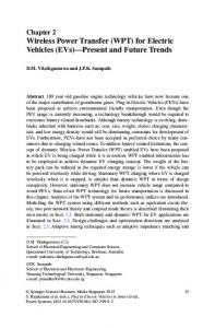
Abstract— Wireless power is one of the new terms that define this century. In the age of mobility, the need for wireless power transfer (WPT) is growing fast. There are several approaches for transferring the electric power wirelessly. In this paper, different methodologies for WPT are investigated as well as advantages, disadvantages and possible applications for each one. In addition, health safety and economical aspects of each applicable approach are discussed. A qualitative comparison between main methods has been achieved based on separation distance, transmitting power, cost, efficiency, and safety. Qi wireless power transfer standard is spreading in low power mobile devices up to 5 Watts and showed great potential for charging high power devices in the future. Keywords — wireless power transfer, Laser power transfer, magnetic resonance, microwave power transfer, Qi standard. I. INTRODUCTION Wireless power transmission (WPT) has become one of the most important research points in this century. The research motivations and its relative importance are related to real time applications. Portability is the main motivation for wireless power transfer as the number of portable devices is enormously increasing and wired chargers will limit their portability. Electric vehicles and mobile robots wide spreading is bonded to the availability of wireless battery chargers because mobility is their main concern. Losses in power transmission grid, which can reach 30% of the transmitted power is a problem that could be solved with microwave power transmission. Nicole Tesla was the first one to introduce the wireless power transfer concept [1]. In 1891, he began his work on wireless power transmission at his laboratory in Colorado, USA. He managed to power a small incandescent lamp by current induced in a three-wound coil and the circuit was grounded at one end and the other end was free [2]. The transmitter used a resonant circuit and was connected to ground. Tesla’s successful experiment was the first demonstration of wireless power transfer concept. The Wardenclyffe tower, shown in Fig. 1, was designed by Tesla for trans-Atlantic wireless telephony. He demonstrated the concept of
ISSN: 2231-5381
wireless power transmission, but the tower was not completed due to lack of fund.
Fig. 1 Wardenclyffe Tower [3] William Brown introduced great contributions to the development of microwave power transmission, which are of great importance recently [2]. He invented the rectifying antenna, called rectenna, which can receive microwaves and convert them to DC current. In 1964, he demonstrated the rectenna ability by powering a helicopter through microwaves only. Wireless power transfer can be achieved by several alternative methods (will be demonstrated and discussed later), but only three of them are the mostly utilized. The first method is the inductive coupling between two separated coils; the second one is the microwave power transmission and the third method is using laser technology for electrical power transfer. Motivations for WPT can be summarized as [4]: Increase the device mobility Avoid the wiring hazards Improve electric vehicles reliability Safe the wiring cost and its isolation Immune to chemicals, dirt and water. Enhance the research of biomedical applications Maintenance free and no electrical plugs II. WIRELESS POWER TRANSFER METHODS A. Inductive Coupling WPT The electrical transformer, represented in Fig. 2 is the simplest application of wireless energy transfer between two coils [5].
http://www.ijettjournal.org
Page 272
International Journal of Engineering Trends and Technology (IJETT) – Volume-40 Number-5 - October 2016
Fig. 2 Basic transformer circuit [6] In mutual induction, the electrical power is transformed from DC into AC at the transmitter and magnetic field is created around the transmitter coil. The receiver coil cuts some of the magnetic field generated by the transmitter coil, and AC current is induced in it. The received AC power is rectified and filtered to produce DC output. As the distance between the transmitter and the receiver coils increases, the receiver coil misses more lines of the magnetic field of the transmitter even in very short distance, so systems built on inductive coupling have low efficiency, so most of the transmitted power is wasted. This method can allow wireless power transfer in the range of millimeters and can reach at most few centimeters [7]. One typical application for electromagnetic induction is electric toothbrush [7]. Most electric toothbrushes use inductive coupling for recharging because daily exposure to water makes charging through an electric plug is unsafe. Wireless recharging allows completely sealed toothbrushes. This application represents one of advantages of wireless power transfer. B. Magnetic Resonance Inductive Coupling Resonant inductive coupling or electro-dynamic inductive effect is the solution for the main problems associated with non-resonant inductive wireless power transfer systems, specially the efficiency dependence on the power transmission distance [8]. By using the resonance concept, power can be transferred between two coils separated by a distance of a few meters efficiently. How can the resonance do that? Each object or structure has a certain natural frequency that is a function of its mass and stiffness. If the excitation frequency and the natural frequency of the structure are matched; the resonance phenomenon occurs. At resonance frequency, the object vibrates with maximum amplitude. That means; a maximum energy is transferred to the object. For that reason, electrical energy can tunnel with maximum efficiency from one coil to another one if they have the same resonant frequency. That was proved by
ISSN: 2231-5381
sending electromagnetic waves around in a highly angular waveguide, which leads to forming evanescent waves [7]. An evanescent wave is nearfield standing wave that exhibits exponential decay with distance and carries no energy. When an appropriate resonant waveguide is close to the transmitter, evanescent waves allow the energy to tunnel, so electromagnetic waves would not propagate through the air causing radiation that wastes power and disturbs electronic devices. In resonant magnetic coupling, the power transmitter and the power receiver inductors are tuned to the same resonant frequency and power transfer occurs over several cycles. This allows significant amount of power to be transferred over distance up to multiple times of the transmitter coil size [8]. Transmitting and receiving coils are usually single layer solenoids or flat spirals with less parasitic capacitance, in contrary to non-resonant coils which are made of multi-layer windings as shown in Fig.3.
Fig. 3 (a) Single-layer coil (b) Multi-layer coil [9] Electrical energy transfer phenomena depend on the principle that if varying electrical current passes through the transmitter coil, a varying magnetic field is formed around that coil. As this varying magnetic field intersects the receiver coil, varying electric current is induced in the receiver coil. This phenomenon is called mutual induction. If the two coils are tuned to the same resonance frequency, it is called magnetic resonance [10]. Resonance enables power transfer with higher efficiency between mutually tuned LC circuits with relatively low coupling factor, so it maximizes energy transfer [5]. However, choosing the proper resonant frequency for certain coil size is also an important factor for optimizing the electrical power transfer. Magnetic resonance induction or near-field, faredge is main idea used for building mid-range power transfer systems. Mid-range can be specified by distance up to ten times the transmitting coil diameter [11]. Systems using inductive coupling can transmit power up to the diameter of the transmitting coil. By implementing magnetic resonance in midrange power transfer systems, they become nearly omnidirectional and still efficient with low losses and low interference with environmental objects [12]. Magnetic resonance is considered the best choice for home devices and appliances as magnetic fields do
http://www.ijettjournal.org
Page 273
International Journal of Engineering Trends and Technology (IJETT) – Volume-40 Number-5 - October 2016
not interact with most common materials. Power transfer is nearly not affected by humans and common everyday objects such as wood, metals and electronic devices, when placed between the primary and secondary coils even if the line of sight is completely obstructed [13]. However, they have a noticeable effect when they are within few centimeters from one of the two coils. Humans and metals can just shift the resonant frequency, but that can be solved though feedback circuits. Other materials like wood can lower the Q factor of coils when placed very close to either one of them, which in turns decreases the efficiency of the power transfer. Tuning the transmitter and receiver to the same resonant frequency ensures that the receiver has a low impedance at the resonance and that leads to optimal absorption of transmitted energy. At the receiver side, the voltage gain is affected by the ratio of the secondary coil inductance to the primary inductance; as the voltage gain is proportional to that ratio [8]. One primary coil can deliver electrical power wirelessly to many receivers as long as they are tuned to the same resonant frequency. One can think that the closer the transmitting and the receiving coils, the more efficient energy transfer, but this is not the case. The highest reachable efficiency can be achieved at a certain distance between the two coils [14]. This distance depends on the chosen resonant frequency and the coil sizes. Increasing the Q factor of the LC circuit leads to increasing the power transfer efficiency. The ratio of the stored power in an LC circuit to dissipated power is the figure of merit or the Q factor. Q factor represents the selectivity of the tuned circuit for resonant frequency.
resonator, which is used in standard Qi transmitters, can be increased by lowering the resistance and/or capacitance [15] as illustrated by Fig. 5 and Fig. 6. Resistance can be lowered by using high quality wires for building coils or thicker wires. However, lowering the capacitance can lead to higher frequency in (1), which limits the current and in turns the amount of power to be transferred due to skin effect which causes the resistance of the coil wire to be proportional to the frequency. Also, single layer coils are preferable as multi-layer coil parasitic capacitance increases the overall capacitance, lowering Q.
Fig. 5 Effect of coil resistance on Q factor.
Fig. 6 Effect of inductance to capacitance ratio on Q factor Fig. 4 Series LC circuit
f
Q
1 2 LC
1 L R C
(1)
(2)
Where f is the resonant frequency, Q is the quality factor, L is the inductance, C is the capacitance of the tank circuit and R is the coil wire resistance. From (2), it is obvious that Q factor for series LC
ISSN: 2231-5381
In [16], researchers point out that the main challenge is to adjust the lumped capacitances at the terminals of the receivers when their position is changed with respect to the transmitter coil and with respect to each other. In [17], high efficiency switched-mode class-E power transmitter was used for achieving low power loss via inductive coupling using planar air coils. This WPT system was able to achieve a desirable power-delivery response across a wide range of load resistances without adding any control mechanism. Advantages of magnetic resonance WPT [8]: Higher efficiency
http://www.ijettjournal.org
Page 274
International Journal of Engineering Trends and Technology (IJETT) – Volume-40 Number-5 - October 2016
Longer distance compared to non-resonant inductive coupling. Allows the use of smaller single-layer planer coils which can be implemented in MEMS circuits for portable and implanted devices. Magnetic fields are not affected by surrounding objects. They can wrap around or penetrate obstacles such as wood, plastics, glass, brick…, Etc. which are transparent to magnetic fields. Safer for people, animal and environment as there is no electromagnetic radiation during energy transfer.
Disadvantages of magnetic resonance WPT: Lower efficiency and increased heating compared to power transfer using wires. Cannot be used in long range applications. C. Wireless Power Transfer Using Microwaves Microwave power transmission (MPT) is now the most efficient far-field technique which allows power transmission for several kilometers in range [5]. This method includes microwave frequencies from 1GHz up to 1000GHz [10]. In microwaves and optical power transmission systems, the reception area can be shaped. This can be achieved through high directivity antennas in microwaves case and laser beams in optical systems case [5]. This is why they can be used to transfer electric power wirelessly over long distances.
Fig. 7 Block diagram of microwaves power transfer system. Microwave power transfer begins with producing the microwaves by using a microwave generator. Generated radio waves then pass though Coax to Waveguide adapter to the waveguide circulator to isolate the microwaves generator and prevent detuning its desired frequency. Then, a tuner and directional coupler are used to separate the waves according to their propagation direction [18]. Finally, microwaves are transmitted through antenna. At the receiver terminal, microwaves are received by a
ISSN: 2231-5381
rectenna, then they pass through a low pass filters, to finally produce DC power. For the microwave generator, devices that are called Microwave Vacuum Tubes are used to generate microwaves and they have several types including klystron, magnetron, and the Travelling Wave Tube (TWT). Magnetron is the most used device [18] which generates microwave by passing electrons through magnetic field [19]. Travelling Wave Tubes are too expensive and power limited, making it unsuitable for practical implementation of power transfer systems [2]. Klystron is the best microwave generator for WPT applications, but it is somewhat expensive. Magnetrons are efficient and cheap, but their output frequency is not precisely controllable as TWT or klystron. Using small magnetrons are advantageous because 300W to 1kW magnetrons are already mass produced for microwave ovens [2]. 2.45GHz is proven practically to be the most efficient frequency to be used in microwave power transmission [18, 20]. For the transmitter antenna, micro strip patch, parabolic dish antennas and slotted wave guide are usually used. Due to its high efficiency, slotted wave guide is used in high power applications. Rectenna, which is used in microwave power receivers, stands for rectifying antenna. It was invented by W.C. Brown in his work in WPT in the 1960s [21, 22]. The rectenna is used to convert microwave energy to DC power. The basic rectenna, shown in Fig. 8, consists of a dipole antenna and RF diode connected between the dipoles [23]. The diode rectifies the received high-power microwave signal and delivers the rectified current to later stages for smoothing and controlling the output DC power delivered to the connected load [10]. As mentioned before, experiments showed that 2.45 GHz frequency achieves the best efficiency for the rectenna. Efficiency exceeding 95% has been realized for modern rectennas [7]. Table I shows a comparison of some types of printed rectennas. TABLE I EFFICIENCY OF DIFFERENT PRINTED RECTENNA [18] Type of Rectenna
Operating Frequency (GHz)
Measured Peak Conversion Efficiency (%)
Printed Diplomo
2.45
85
Circular Patch
2.45
81
Printed Dual Rhombic
5.6
78
Square Patch
8.51
66
http://www.ijettjournal.org
Page 275
International Journal of Engineering Trends and Technology (IJETT) – Volume-40 Number-5 - October 2016
Fig. 8 Simple rectenna [24] In 1980s, Canada's Communications Research Centre introduced the first practical application for MPT system by designing a small unmanned airplane powered by microwaves beamed from ground [7]. This plane was called the Stationary High Altitude Relay Platform (SHARP) and it was used as a communication relay. The SHARP could fly in a circle with 2-kilometer diameter at altitude of about 21 kilometers. But, the most impressive ability of this plane is that it can fly for months without landing.
The main problem associated with SPS power transmission is its effect on human and animal health. Mega-watt microwaves beams can cause undesirable side effects to human or animal tissues if they diffract from their targeted receiver station. A large receiving area can be utilized to power many smaller receivers and in the same time, retain low power density for electromagnetic exposure safety. A distributed power density of 1mW/cm2 over an area with 10 Km diameter can achieve a total power of 750 Megawatts while keeping the radiation level in the safe zone [5].
Fig. 10 Solar Power Satellite [24]
Fig. 9 The SHARP unmanned plane [7] A large disk-shaped rectenna behind its wings receives the transmitted microwaves sent by groundbased power transmitter, and converts them into rectified electrical current. As the plane flies in the power transmitter effective range which is circular, it can receive continuous electric power. This is why its flight path is circular. The new application that uses microwaves to transmit power, is Solar Power Satellites (SPS). Satellites equipped with large solar panels, convert the generated electricity by these solar panels, to high power microwaves beams and direct them toward ground-based receiver stations that have very large rectennas. To maintain a good lock on the rectenna, the satellite needs to have a retrodirective transmitter which locks on to a pilot beam sent from the ground station [2]. Most researches depend on frequencies in 2.4GHz to 5.8GHz range to achieved reasonable efficiencies, but this can cause spectrum regulatory issues as many communication devices already operate in the same range. Japan is planning to send low earth orbit satellite with power transmission capability of 10 to 100 kW, to prove its feasibility [25].
ISSN: 2231-5381
D. Power Transfer by Laser Laser power beaming is mainly researched in military weapons development and space applications [5]. When it comes to power transfer, this technology is used in relatively short distance application. This is because laser beams can harm humans and animals if they cut the laser beam path. For electric power transmission by laser, the electric current is first converted to high density laser (light) and at the receiver side, high efficiency photo voltaic cells are used to convert the received laser beam back into electricity. The overall laser power transmission system efficiency is about 50% which is quite low compared to the other wireless power transfer methods [10].
Fig. 11 Wireless Power Transmission through Laser [3]
http://www.ijettjournal.org
Page 276
International Journal of Engineering Trends and Technology (IJETT) – Volume-40 Number-5 - October 2016
E. Summary of WPT methods A comparison of different wireless power transfer methods is shown in Table II. This comparison highlights the strong and weak points for each technique. TABLE II COMPARISON OF DIFFERENT WPT METHODS Distance between transmitter and receiver circuits Inductive a few millimeters Coupling Magnetic a few meters Resonance Microwaves up to 100 kilometers Laser a few meters but could be used for longer distances by using high intensity beam Transmitted Power Inductive Up to a few watts Coupling Magnetic Up to a few kilo watts Resonance Microwaves Up to hundreds of Megawatts Laser Up to hundreds of Megawatts [26] Efficiency Inductive Low Coupling Magnetic High Resonance Microwaves High Laser Low Cost Inductive Economical because the used Coupling equipment are cheap and available Magnetic Economical because the used Resonance equipment are cheap and available Microwaves Relatively expensive compared to other methods Laser same economic conditions of inductive coupling Safety Inductive It is safe from biological point of Coupling view Magnetic It is safe from biological point of Resonance view Microwaves Dangerous on health due to high frequency rays (1 GHz to 1000 GHz) Laser injurious to human health III. QI STANDARD In 2008, the Wireless Power Consortium was founded and more than 220 international companies are now members of it [27]. The first wireless power standard was released by the consortium for lowpower mobile devices up to 5 Watts. The standard includes systems that uses inductive coupling
ISSN: 2231-5381
between two planer coils to transfer power form the transmitter and the receiver. The key advantage of this standard is that it makes use of coils for control data transmission from the receiver to the transmitter, so the communication is only one way from the receivers to the base station [28].
Fig. 12 Basic Qi system overview [29] Wireless power consortium added an improvement to the Qi standard by including magnetic resonance wireless charging. The charging distance was increased to allow devices to be charged from distance up to 40mm while keeping compatibility with Qi standard [28]. A. The Power Transmitter Under Wireless Charging Standard In this standard, the power transmitter design is restricted to certain implementations to ensure compatibility with different power receiver devices. The receiver presents itself to the transmitter as a compliant device and provides the required charging configurations. The device can have fixed or moving coil configurations. The transmitter operates in resonant mode with controllable duty cycle and frequency which can be changed between 100 and 205 kHz, depending on the power demands [29]. The input voltage ranges from 5 VDC to 19 VDC according to the transmitter type. The design of the transmitter is limited to three types: Guided positioning, free positioning moving transmitter coil and free positioning coil matrix [28].
Fig. 13 Positioning of receiver coil with respect to the transmitter coil [28]
http://www.ijettjournal.org
Page 277
International Journal of Engineering Trends and Technology (IJETT) – Volume-40 Number-5 - October 2016
A power transmitter can serve only one power receiver at a time, but a base station may contain multiple power transmitters to serve several devices. B. Received Power Under Wireless Charging Standard The received voltage is full-wave rectified with efficiency equals about 70% for an output of 500mA at 5VDC [28]. The power transfer is achieved by magnetic coupling between the power transmitter and receiver. But, uncoupled field lines do not represent a loss as they rotate around the primary coil, except if there is a parasitic load (e.g. eddycurrent loss in metals). Unlike to the power transmitters, the design of power receivers is left free to the device manufacturer [28].
More flexibility for positioning devices to be charged. Ability to charge up to 8 devices simultaneously. Use of Bluetooth for communication, which exists in wide range of devices C. Disadvantages of Rezence standard Lower efficiency than Qi standard. No compatibility with Qi standard, which is implemented in large number of devices.
IV. REZENCE STANDARD Rezence is a newly-developed wireless power transfer standard introduced by Alliance for Wireless Power. This standard is developed to provide more features than the Qi Standard. A. Description Rezence depends on magnetic resonance technology to transfer power between a power transmitter and a power receiver. In contrary to Qi systems, Rezence systems relay on loose coupling between the power transmitter unit (PTU) and the power receiver unit (PRU) [30]. This means that the system can operate efficiently with low coupling factor. As a result, the standard allows higher distance between the PTU and PRU compared to Qi systems (up to 50 mm) and the system is tolerant to misalignment of the charging coils which increases flexibility. A system overview is represented by Fig. 14. Another difference between Rezence and Qi standards is that the first operates at high frequency of 6.78 MHz and a single PTU can charge up to 8 PRUs at the same time at a maximum of 50 Watts in total. The communication between the PTU and PRUs is carried over 2.4GHz Bluetooth links using Bluetooth Low Energy (BLE) technology which is available in most new Bluetooth-enabled devices. The PTU uses this BLE links for identification and controlling power levels of valid loads and protection of non-compatible devices. Unlike Qi standard, Rezence does not impose constrains in the design of PTUs nor PRUs. The loose coupled coils which allows spatial freedom comes at the cost of efficiency. Qi standard provides higher power transfer efficiency than Rezence standard at the same load and good coils alignment. B. Advantages of Rezence standard
Higher maximum transmitter power up to 50 W.
ISSN: 2231-5381
Fig. 14 Rezence WPT System V. FEASIBILITY OF WPT The use of WPT is feasible for the following advantages [4, 28]: A. Safety No electric shocks or short circuiting. Safe on humans and animals. Sealed power sources and devices allow more children protection. No corrosion can happen. B. Durability No moving mechanical parts that require maintenance. Water proof and weather proof (for inductive coupling). Impervious to chemicals and dirt. Rugged and tough devices are possible. Low-profile, does not occupy much space No wires to be cut or worn. Consistent and secure connections. C. Ease of use No need for electrical plugs. Data can be transmitted wirelessly at the same time of charging process. Auto charging, so one cannot forget to plug-in. A universal charger can be designed. Easier implanted devices charging. D. Aesthetics Avoids unnecessary street clutter. Perceive historic city aesthetics. Maintain precious footpath area.
http://www.ijettjournal.org
Page 278
International Journal of Engineering Trends and Technology (IJETT) – Volume-40 Number-5 - October 2016
Unpleasant removed.
overhead
cables
can
be
Disadvantages of WPT: The main concern about wireless power transfer is its biological effects. Resonant inductive coupling has far lower effects compared to microwaves power transmission technique, but has a far lower range. Safety studies and researches pointed out that the radiation level of WPT is nearly equal to or slightly than the radiation of cellular phones. [31]. The very high initial cost for implementing WPT systems is a problem that can lead to lower spreading rate. Security is required as power can be easily stolen [32]. Lower efficiency and increased resistive heating compared to direct contact [28]. Qi standard is available only for low power transfer up to 5W. Clear line of sight is a must for microwaves power transmission. MPT can cause interference problems for existing communication systems. Microwaves behavior depends on media through which they travel. So, weather can easily affect the MPT efficiency [33]. Beam-forming and directivity is extremely important for achieving high efficiency wireless power transfer through using microwaves [34]. MPT is not suitable for powering a moving target because the directional antenna should be locked onto the moving receiver and this cannot happen in practice. Also, omnidirectional antennas are very inefficient. VI. PRODUCTS BASED ON WPT A. Wireless Power Broadcasting This is a one-to-many system in which one wireless power source can deliver electric power to many devices with different power requirements [11]. Despite of being a very important application for WPT especially for indoor use, many challenging problems will face the system designer. For achieving good efficiency and lower heat dissipation, transmitted power should be tailored to the power demand because the load can change with time either by increasing or decreasing power demand. So, communications between the source and target devices should be maintained to track the power demand. Broadcasting power can lead to interference issues which threat the system efficiency and even functionality.
ISSN: 2231-5381
B. Duracell’s myGrid It uses technology licensed from WildCharge [14]. It consists of a conductive grid, arranged so that it will always match the electrode spacing of the “warts” which the user adds on a mobile device. This allows WPT from the myGrid electrode shown in Fig. 15, to the wart at about 100% efficiency.
Fig. 15 Duracell’s myGrid [14] C. Powermat Charging Pad These inductive charging pads designed by Powermat. Powermat has over 40 applied patent for achieving efficiencies ranging from 80% to 92% [14]. However, to achieve these efficiencies, the mobile should be placed with millimeter precision. D. Fulton Inductive Coupling Fulton Innovation used inductive coupling in its system and claims that it is superior because it can optimize the power transfer in real-time thanks to its intelligent resonant frequency tuning subsystem [14]. The system can achieve up to 98% efficiency.
Fig. 16 Fulton Innovations’ eCoupled Wireless inductive coupling charger [14] E. Power Pad by Philips Philips Research has developed wireless charging pad called “Power Pad” shown in Fig. 17 [28]. It consists of an array of transmitter cells and each cell contains a detector which controls the cell activation and termination. The cell is activated only when a device is placed on it. However, the Power Pad is not compatible to Qi standard. It operates at 500 kHz can transmit 1.2W with one transmitter cell.
Fig. 17 Philips’ Power Pad [28]
http://www.ijettjournal.org
Page 279
International Journal of Engineering Trends and Technology (IJETT) – Volume-40 Number-5 - October 2016
VII. CONCLUSION Based on this study, we can say that the magnetic resonance WPT is the most promising technique for powering devices wirelessly with high efficiency over up to few meters. Being safe for humans and environment, magnetic resonance WPT can spread to be the standard charging method for most portable devices in the next few years. So, we recommend researchers to focus on this technology. Even though, microwave power transfer is trying to find its way to replace high power transmission lines. Due to health concerns, many researches should be done to find a safe solution that could enable using microwaves for long-distance high power transmission. Qi standard has to be upgraded for different power levels with precaution to human health. REFERENCES [1] [2]
[3]
[4]
[5]
[6]
[7]
[8] [9]
[10]
[11]
[12]
[13]
[14] [15]
Nikola Tesla, “Colorado Springs notes 1899-1900,” 1999, ISBN-10: 8087888243. Sagolsem Kripachariya Singh, T. S. Hasarmani, and R. M. Holmukhe, "Wireless Transmission of Electrical Power Overview of Recent Research & Development," International Journal of Computer and Electrical Engineering, Vol.4, No.2, April 2012. Senthil Nathan.M and Pandiarajan.K, "A Review Of Wireless Power Transmission," IJERA,Vol. 3, Issue 1,2013, pp.1125-1130; ISSN: 2248-9622. Grant covic and John boys,"Inductive power transfer (IPT) powering our future," presentation, Auckland Uniservices Ltd, 2010. Dilip Chaurasia,Santosh Ahirwar, "A Review on Wireless Electricity Transmission Techniques," Current Trends in Technology and Science, Volume: 2, Issue: 4, July 2013, ISSN: 2279–0535. “Transformer,” [Online]. Available: en.wikipedia.org/wiki/Transformer, last date of visit: 4 September, 2016. Vikash Choudhary, Satendar Pal Singh Vikash Kumar and Deepak Prashar, "Wireless Power Transmission: An Innovative Idea," International Journal of Educational Planning & Administration; Volume 1, Number 3 (2011), pp. 203-210; ISSN 2249-3093.. Basharat Nizam, "Inductive Charging Technique," IJETT, Volume4, Issue4; April 2013;ISSN: 2231-5381. Image [Online]. Available: http://showwell.manufacturer.globalsources.com/si/ 6008822165919/pdtl/Air-coil/1120315405/Air-ChokeCoil.htm, last date of visit: 4 September, 2016. A. Mahmood, A. Ismail, Z. Zaman, H. Fakhar, Z. Najam, M. S. Hasan and S. H. Ahmed "A Comparative Study of Wireless Power Transmission Techniques," Journal of Basic and Applied Scientific Research, 2014, ISSN 20904304. David W Baarman and Joshua Schwannecke "UNDERSTANDING WIRELESS POWER", Fulton Innovation LLC, December 2009. A. Karalis, J. D. Joannopoulos and M. Soljačić, "Efficient wireless non-radiative mid-range energy transfer," Ann. Phys., 10.1016/j.aop.2007.04.017 (2007). André Kurs, et al. , "Wireless Power Transfer via Strongly Coupled Magnetic Resonances," Science 317, 83 (2007); DOI: 10.1126/science.1143254. "Alternative Energy", EETimes; June 21, 2010. Brent Griffin and Carrick Detweiler, "Resonant Wireless Power Transfer to Ground Sensors from a UAV," IEEE
ISSN: 2231-5381
[16]
[17]
[18]
[19]
[20]
[21]
[22] [23]
[24]
[25]
[26]
[27]
[28]
[29]
[30]
[31] [32]
[33] [34]
International Conference on Robotics and Automation (ICRA), 2012 ;DOI:10.1109/ICRA.2012.6225205. B. L. Cannon, J. F. Hoburg, D. D. Stancil, et al., “Magnetic Resonant Coupling As a Potential Means for Wireless Power Transfer to Multiple Small Receivers,” IEEE Trans. Power Electronics, Vol. 24, No. 7, pp. 1819-1825, 2009. Z. N. Low, R. A. Chinga, R. Tseng, et al., “Design and Test of a High- Power High-Efficiency Loosely Coupled Planar Wireless Power Transfer System,” IEEE Trans. Industrial Electronics, Vol. 56, No. 5, pp. 1801-1812, 2009. M.Venkateswara Reddy, K.Sai Hemanth, CH.Venkat Mohan, "Microwave Power Transmission – A Next Generation Power Transmission System," IOSR-JEEE, Volume 4, Issue 5 , PP 24-28, e-ISSN: 2278-1676 (Jan. Feb. 2013). “Cavity magnetron” [Online]. Available: en.wikipedia.org/wiki/Cavity_magnetron, last date of visit: 4 September, 2016. Wen Huang, Biao Zhang, Xing Chen, Kama Huang and Changjun Liu, "Study on an S-Band Rectenna Array for Wireless Microwave Power Transmission," Progress In Electromagnetics Research, Vol. 135, 747 -758, 2013. Brown, William C., "The History of Power Transmission by Radio Waves," IEEE Transactions on Microwave Theory and Techniques, vol. MTT-32, no. 9, September 1984. “Rectenna” webpage: en.wikipedia.org/wiki/Rectenna. Yeoh, W, "Wireless power transmission (WPT) application at 2.4 GHz in common network," Thesis ,RMIT University, 2010. M. Maqsood and M. Nauman Nasir, "Wireless electricity (Power) transmission using solar based power satellite technology," 6th Vacuum and Surface Sciences Conference of Asia and Australia (VASSCAA-6), 2013, doi:10.1088/1742-6596/439/1/012046. G. E. Maryniak, “Status of international experimentation in wireless power Transmission,” Sunset energy counsel, Solar energy, vol. 56, 1996. Leopold Summerer, and Oisin Purcell. "Concepts for wireless energy transmission via laser." Europeans Space Agency (ESA)-Advanced Concepts Team, 2009. “Wireless Power Consortium” [Online]. Available: https://www.wirelesspowerconsortium.com, last date of visit: 4 September, 2016. P.Manivannan and S.Bharathiraja,"Qi Open Wireless Charging Standard – A Wireless Technology for the Future;” ijecs ,Volume 2 Issue 3 March 2013 Page No. 573-579; ISSN:2319-7242. "Wireless Power Transfer System Description," Qi standard, Volume I: Low Power, Part 1: Interface Definition, Version 1.1.2, June 2013. Pratik Dubal, “Rezence – Wireless Charging Standard based on Magnetic Resonance,” International Journal of Advanced Research in Computer and Communication Engineering, Vol. 4, Issue 12, December 2015. Vaessen, Peter, "Wireless power transmission," KEMA, September 2009. Mankins, J., Nobuyuki Kaya, and Massimiliano Vasile, "Sps-alpha: The first practical solar power satellite via arbitrarily large phased array," (a 2011-2012 nasa niac project) 10th International Energy Conversion Engineering Conference, 2012. Rajeev Mehrotra, "Cut the Cord: Wireless Power Transfer, its Applications, and its limits," cse.wustl.edu. April 2014. Shinohara, Nobuhiro, Yuji Kubo and Hiroshi Tonomura, "Mid-Distance Wireless Power Transmission for Electric Truck via Microwaves," Electromagnetic Theory (EMTS), Proceedings of 2013 URSI International Symposium on. IEEE, 2013.
http://www.ijettjournal.org
Page 280