Dec 5, 2012 - the concept of a web page cookie â where a cookie is datastore on a client .... The Analyser can also provide a definitive list of the elements that ...
(IJACSA) International Journal of Advanced Computer Science and Applications, Vol. 4, No.5, 2013
Data Flow Sequences: A Revision of Data Flow Diagrams for Modelling Applications using XML. James PH Coleman Edge Hill University St Helen’s Rd, Ormskirk, UK, L39 3LG.
Abstract—Data Flow Diagrams were developed in the 1970’s as a method of modelling data flow when developing information systems. While DFDs are still being used, the modern web-based which is client-server based means that DFDs are not as useful. This paper proposes a modified form of DFD that incorporates, amongst other features sequences. The proposed system, called Data Flow Sequences (DFS) is better able to model real world systems in a way that simplifies application development. The paper also proposes an XML implementation for DFS which allows analytical tools to be used to analyse the DFS diagrams. The paper discusses a tool that is able to detect orphan data flow sequences and other potential problems. Keywords—Data Flow Diagrams; Modelling diagrams; XML; Data Flow Sequence Diagrams
I.
INTRODUCTION
Data Flow Diagrams (DFDs) [1] were developed in the late 1970’s as a method of modelling the flow of data through an information system. According to Bruza [2] they are often used in the preliminary design stages to provide an overview of the system. Today there are a number of advanced modelling tools (including UML [3] – which was developed by Grady Booch, Ivar Jacobson and Jim Rumbaugh at Rational Software in the 1990s) and Business Activity Models [4] and other tools) that not only describe the data flow, but also specify the processing steps involved. These tools can then be (in some cases) to automatically develop the code. Data flow diagrams are one of essential perspectives of the structured-systems analysis and design method SSADM [5]. SSADM is one particular implementation and builds on the work of different schools of structured analysis and development methods. Kolhatkar [6] proposed the development of an XML representation of DFDs to overcome a number of identified weaknesses with the graphical DFDs used. These included: the amount of time it takes to actually “draw” the DFDs given that DFDs are usually developed iteratively and ambiguity in understanding given that there are a number of different models in drawing DFDs. There exists at least 2 major versions (Yourdon & Coad [7] and Gane & Sarson [8]). II. DATA FLOW SEQUENCE DIAGRAMS In this paper we will consider a revised and modernised form of DFD that is better suited to modern applications, particularly web-based applications. Web based applications
are characterised by the client-server nature of the relationship – where the main entity (the User) communicates with a client system (usually called a web browser), and the web browser then communicates with one/more servers (called web servers) which may themselves communicate with other processes using system systems as SOAP [9] HTTP-based systems. The main difference between an application and a webbased application stems from the fact that web-based applications exists within a context of a web-page that is displayed by the web browser. This web-page is downloaded from the web server, which is again in the context of a webpage (the application). This means that all data flows communicate with processes that are sub-components of a page (or group of processes), and these pages are downloaded from pages from the Server. In order to support this extended definition, DFS diagrams include the concept of sequence – that is, dataflows are sequenced. This indicates the sequence in which dataflows, and processes/entities receive data, process data and then produce output. Processes run on either the Client system, the Server system or on a separate system detached from the client or server. An example of this would be a DB server. Even though a DB system (or datastore) may actually be running on the same networking device as the web server, by putting it as being separate from the Web Server, this indicates that the DB server may be physically separate. Kolhatkar [6], in his proposal for representing DFDs in XML, established a number of XML tags, including: , , and , each with a number of attributes. Processes, entities and data stores have an id attribute that is used in the dataflow to identify the source and destination tags. This article introduces a number of new concepts to the DFD, forming the Data Flow Sequence Diagrams (DFS). These changes are: The Introduction of a Client and Server as sites for executing processes, and On the Client and Server, there are Process Groups (called a procgroup) which conceptually form a page equivalent for web-based applications.
28 | P a g e www.ijacsa.thesai.org
(IJACSA) International Journal of Advanced Computer Science and Applications, Vol. 4, No.5, 2013
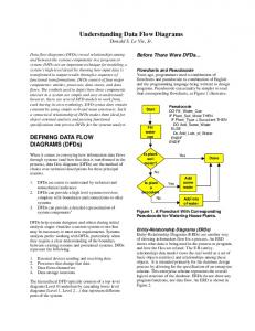
Clients and procgroups allows the Designer to introduce the concept of a web page cookie – where a cookie is datastore on a client and inside a procgroup, so that if the procgroup closes then the datastore is lost. This mimics the behaviour of page-bound cookies which are only accessible from the current web page, and when the web page is replace, then the cookie is removed. At the same time, the cookie is also accessible to the same web-page (procgroup) on the server. Similarly, processes, datastores and the server allows DFS to mimic the PHP session variable – which is a variable that only exists on the server. It has a wider scope than the procgroup, but always only exists on the server. rocesses exist on both clients, and servers. Processes can be executed inside a procgroup, if it is a process created by a web page, or outside the procgroup environment as would happen for instance with a PHP DB request, which comes from a process in a procgroup on the server and is sent to a DB server for processing, and then returned. Irrespective of whether a process is in a procgroup or not, dataflows connect entities to/from processes, datastores to/from processes or process to/from process. Figure 1 illustrates a DFS diagram that represents a sub-set of the Guest Book system where the User has supplied his personal information, this data is stored in a DB, and then all guest book entries are displayed. In this example, there is a procgroup that is labelled “cgbook.php” which indicates that the included processes are a part of the gbook.php file on the Client. Similarly, there is a procgroup called sgbook.php which includes the processes that are executed on the Server.
Fig. 1
III. XML REPRESENTATION Figure 2a illustrates how a portion of this DFS is represented in XML. For clarity, the Context diagram has been removed, as has a number of the context-level dataflows. ... User request page
web
Display Page
Web
Obtain Data
User
Display Guest Book and prepare for next entry
DFS diagram for Guest Book Example system
29 | P a g e www.ijacsa.thesai.org
(IJACSA) International Journal of Advanced Computer Science and Applications, Vol. 4, No.5, 2013
load page
web
Entry
Process
Guest
Book
Guest DB
Book
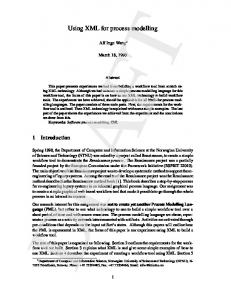
Enter user data Submit Form Submit Form Data Store User Data Request GB Data Retrieve GB Data Display GB Data … Fig 2a: Figure 2a illustrates a simplified implementation of a web-based guest-book application.
Each process, entity, dataflow, datastore, procgroup has a unique identifier. The uniqueness of these different objects enable the dataflows to specify the relevant process, entity or datastore without needing to distinguish between local and global identifiers, and also allows dataflows to link between levels. That is, a Level 2 DFS diagram is able to reference an entity at a higher (or lower) level.
seq CDATA #REQUIRED >
30 | P a g e www.ijacsa.thesai.org
(IJACSA) International Journal of Advanced Computer Science and Applications, Vol. 4, No.5, 2013
Fig2b:
provides the DTD for the DFS XML representation.
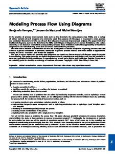
IV. DFS VALIDATION AND ANALYSIS Having the DFS being represented using XML enables automatic validation and analysis of the DFS diagram to ensure the diagram truly represents the real world. As an example, an analyser tool has been developed that is able to follow the flow of data from process to process. It is also possible to start at a dataflow and back-track to find out where the data came from. Figure 3 illustrates part of the track of a dataflow in the system described in Figure 2 above – the Guest Book system. Here the tool shows the different paths. By holding the mouse over a dataflow, you are able to see the destination process/entity/datastore.
Datastores where there are input but no output dataflows Datastores has output dataflows but no input dataflows. Dataflows between entities without an intervening process Dataflows between datastores without an intervening process The Analyser can also provide a definitive list of the elements that make up the DFS diagram in the form of a symbol table that lists all the key information about the entities, processes and datastores showing whether they are client/server/other based and whether the a process is part of a procgroup. Similarly the system shows all dataflows, and indicates which element it is connected to. In this way the tool aids the designer is locating data flows and process orphans. V. CONCLUSIONS DFS Diagrams enable developers to model real world applications with a much richer diagrammatic system than the traditional Data Flow Diagram. DFS Diagrams are specifically designed to support web-based applications with the concept of a client and server being an integral part of the DFS system. With the ability to specify the DFS Diagram using XML, then the diagram can be analysed using XML processing tools such as XPath and XSL. Further, the XML representation can also be used to analyse the DFS diagram looking for fundamental errors in design, as well as the ability to follow a dataflow in sequential order from any starting point to the logical end of the dataflow. The XML representation can be expanded to include code specification, and in this way can be sued to automatically create applications. The Analyser currently provides a limited set of validation and analyser tools. Given the flexibility of XML and its efficiency in processing, other analytical tests can be incorporated into the system to aid finding logical and practical problems with the DFS design. [1] [2] [3] [4]
[5] [6] Fig. 2
DFS Analyser
Analysers can also search for a number of anomalous conditions such as:
Where there exists a process for which there output dataflows but no input data flows Where there exist a process that has an input dataflow (or dataflows) but no out dataflow. Processes where there are no connecting dataflows.
[7] [8] [9]
REFERENCES W. Stevens, G. Myers, L. Constantine, "Structured Design", IBM Systems Journal, 13 (2), 115-139, 1974. Bruza, P. D., Van der Weide, Th. P., "The Semantics of Data Flow Diagrams", University of Nijmegen, 1993 Marc Hamilton, “Software Development: A Guide to Building Reliable Systems” p.48; Prentice Hall, 1999. Cadle, J, Eva M, Hindle K, Paul D, Rollaston C, Tudor D, Yeates D: “Business Analysis” 2nd Edition; British Informatics Society Limited; 2010 SSADM. “Business Systems Development with SSADM”. The Stationery Office. 2000. p. v. ISBN 0-11-330870-1. S S Kolhatkar “XML Based Representation of DFD: Removal of Diagramming Ambiguity” International Journal of Advanced Computer Science and Applications, Vol. 2, No. 8, 2011 Coad, P.. Yourdon E, “Object-Oriented Analysis”, 2nd Edition, Englewood Cliffs, NJ: Prentice-Hall, 1991. C. Gane and T. Sarson. “Structured Systems Analysis: Tools and Techniques", New York: IST, Inc., 1977 Simple Object Access Protocol (SOAP) 1.1, W3C Note 08 May 2000; http://www.immagic.com/eLibrary/ARCHIVES/SUPRSDED/W3C/W0 00520N.pdf Accessed 8/1/2013.
31 | P a g e www.ijacsa.thesai.org