PROBLEM ABSTRACTION AND SIMPLIFICATIONS. In the following, it is assumed that. 1) the other traffic participants with the right of way neither slow down nor ...
A Robust Algorithm for Handling Moving Traffic in Urban Scenarios Moritz Werling1 , Tobias Gindele2 , Daniel Jagszent2 , and Lutz Gr¨oll3 1 Institute of Applied Computer Science/Automation 2 Institute of Computer Science and Engineering University of Karlsruhe (TH), 76128 Karlsruhe, Germany 3 Institute of Applied Computer Science Forschungszentrum Karlsruhe (FZK), 76021 Karlsruhe, Germany {moritz.werling, lutz.groell}@iai.fzk.de
Abstract— This paper describes an algorithm for handling moving traffic which was deployed on AnnieWAY, an autonomous vehicle successfully entering the finals of the DARPA Urban Challenge 2007 competition. The algorithm allows for a robust and effective collision check for a variety of maneuvers including turning at intersections with oncoming traffic, merging into moving traffic, changing lanes, as well as dynamic passing and can easily be integrated into a high-level decision process, such as a state machine.
I. INTRODUCTION The Urban Challenge 2007 is a research program conducted in a competitive format to address the challenging aspects of letting vehicles accomplish missions in urban scenarios fully autonomously. In this competition, handling moving traffic (see e. g. [1]) turned out to be a mayor difficulty as most teams failed here. This paper describes an algorithm of AnnieWAY [4], which reduces dynamic maneuvers, such as merging into moving traffic and crossing intersections with oncoming traffic, to static maneuvers, such as simple turns. Unfortunately, the actual behavior of the other traffic participants cannot be exactly predicted. Therefore certain assumptions, simplifications and conservative estimates have to be made in an appropriate way, such that the unmanned vehicle operates safely as well as effectively. II. P ROBLEM ABSTRACTION AND SIMPLIFICATIONS In the following, it is assumed that 1) the other traffic participants with the right of way neither slow down nor speed up, 2) stay in the middle of the road, 3) AnnieWAY’s longitudinal controller accelerates at a known constant rate until the desired maneuver velocity is met and 4) all traffic participants’ velocities and positions are known. Assumption (1) and (2) have to be made, since the actual behavior of the other vehicles (Bi ) cannot be precisely predicted. Therefore it is assumed, that the considered vehicles travel at a constant velocity in the center of the priority road. Introducing tBP as the time needed for traveling a distance dBP in the road center and vB as the other vehicle’s constant velocity, leads to d tBP = BP . (1) vB
{gindele, jagszent}@ira.uka.de
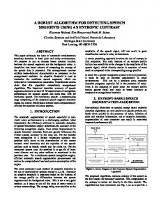
Assumption (3) needs some further explanation of the control strategy. The implemented longitudinal controller inverts the vehicle’s powertrain dynamics in order to convert a desired acceleration into brake and acceleration pedal values sufficiently accurately. A simple proportional velocity controller is combined with a saturation element (asat ), which prevents the vehicle from heavy braking or accelerating, when the desired velocity changes discontinuously. The resulting drive-off characteristic v(t) from a start velocity v0 to a new desired velocity vd can be seen on the left in Fig. 1 as a dashed line along with the approximation vˆ(t) as a solid line.
Fig. 1.
Actual and approximated drive-off characteristic
Here tsw denotes the time, when the approximated velocity vˆ(t) reaches vd . It can be calculated by vd − v0 tsw = . (2) asat An integration of vˆ(t) over time yields the traveled distance of AnnieWAY (A) � 2 v0 t + asat t ≤ tsw 2 t dAP (t) = asat 2 v0 tsw + 2 tsw + vd (t − tsw ) t > tsw , (3) as can be seen on the right in Fig. 1. Solving (3) for t with 2 dAP − v0 tsw − asat 2 tsw + tsw v0 + asat tsw
(4)
ta > tsw qta 2 v0 + 2asat dAP ) ta ≤ tsw , asat (−v0 +
(5)
ta = yields ( tAP =
1
whereas the ambiguity of the solution was resolved.
Fig. 3 through 6 illustrate the transfer of different traffic scenarios to the equivalent graphs, whose generic graph can be found in Fig. 2 along with the four relevant quantities to be measured, the current distances dA (t) and dB (t) to M P and the current velocities vA (t) and vB (t) (assumption (4)). As can be seen, traffic participants are all assumed to be point masses.
Fig. 5.
Fig. 2.
Lane change maneuver
Relevant measurements on simplified graph
Fig. 6.
Double lane change maneuver with oncoming traffic
III. S PATIAL AND TEMPORAL VERIFICATION
Fig. 3.
Fig. 4.
Right turn after stopping
On the one hand, at low speed it has to be guaranteed that the autonomous vehicle does not interfere geometrically, e. g. gets too close or even collide with another traffic participant. Therefore spatial safety distances were introduced (see Fig. 7). On the other hand, spatial safety distances are not a proper measure for higher speeds. In this case a temporal safety distances assures certain time gaps between AnnieWAY and the other traffic participants. Since time gaps become too small referred to the ground at low speed in turn, both spatial and temporal conditions have to be fulfilled at the same time.
Left turn without stopping
Based on the previous equations and graphs, the movement of the vehicles can be predicted and used for collision detection in the next section.
Fig. 7.
Geometric parameters
For simplicity’s sake only a single vehicle is considered
initially. In order to drive in the first place through the critical area, the following two conditions have to be met: 1) At time tBP , when B reaches PB1 , A has to be B1 beyond PA2 . f reespat,AB = (dAP (tBP
B1
) > dA + DA2 )
(6)
2) After A has passed M P , a pregiven time span ∆TAB has to elapse, before B reaches M P . f reetemp,AB = (tBM P > tAM P + ∆TAB )
(7)
In order to drive in the second place, the following two conditions have to be met: 1) At time tBP , when B reaches PB2 , A may not have B2 passed PA1 yet. f reespat,BA = (dAP (tBP
B2
) < dA − DA1 )
(8)
2) After B has passed M P , a pregiven time span ∆TBA has to elapse, before A reaches M P . f reetemp,BA = (tAM P > tBM P + ∆TBA )
(9)
This means if f ree = (f reespat,AB ∧ f reetemp,AB ) ∨ (f reespat,BA ∧ f reetemp,BA )
(10)
is true, it is assured that neither A is between PA1 and PA2 as long as B is between PB1 and PB2 nor the time gaps in M P are shorter than permitted. IV. DYNAMIC PASSING Yet another timing-critical maneuver is the passing of a moving vehicle. In order to keep the formulas above, one has to switch from absolute to relative velocities. That means that a vehicle’s velocity will be decreased by the velocity of the vehicle being passed if it moves into the same direction, whereas it will be increased by the same amount if it moves into the opposite direction. As a result a graph can be simply chosen that represents the movement relative to the vehicle being passed and the same formulas apply as for the static passing maneuver (Fig. 6). V. S CENARIOS WITH MULTIPLE TRAFFIC PARTICIPANTS The extension from a single vehicle B to n vehicles Bi is straightforward, as shown in Fig. 8. Vehicle 1, 3, 4, and 6 pass the check, whereas vehicle 2, 7, and 8 fail. As long as
one vehicle fails the verification, A is not allowed to enter the critical zone: f reetot = f ree1 ∧ f ree2 ∧ · · · ∧ f reen
(11)
There are scenarios, where it is not obvious which decision a traffic participant with the right of way will make. One can think of an approaching vehicle as in Fig. 4, which might eventually turn right or go straight. In these cases multiple hypotheses have to be checked in the same way, as if there were multiple vehicles on different routes. VI. C HOICE OF PARAMETERS In the DARPA Urban Challenge 2007 the parameters for each scenario primarily depend on the road geometry and speed limits, which both are given in the RNDF1 . The parameters represent a trade-off between safety and efficiency (time) and need to account for simplifications as listed in Sec. II as well as measurement uncertainty. Many scenarios demand an asymmetric choice of parameters, such as left turns with oncoming traffic (yield turns). For safety reasons ∆TAB should here always be bigger than ∆TBA , since the impact of a front crash with a faster vehicle exceeds the one of a side collision by far. VII. I NTEGRATION INTO THE STATE MACHINE AnnieWAY’s planning component is implemented as a hierarchical state machine [2] that always deploys the Moving Traffic Check (MTC) when AnnieWAY might come into conflict with other traffic participants demanding the same traffic space (conflict spaces). Contingent upon the result obtained from the MTC and the particular situation (conflict situations), state transitions are triggered and the resulting state generates the desired path and approves the free section for the longitudinal control. In order to prevent frequent switching back and forth between states due to measurement noise and control inaccuracy, hysteresis in the MTC is introduced by � k case state driving with k ∈ (0, 1) h= 1 case state stopping and the modified parameters Dh,xx = h · Dxx Th,xx = h · Txx . That means that the requirements are slightly reduced once the autonomous vehicle set itself in motion. Since the actual behavior of the other traffic participants can be roughly predicted at best, additional safety layers are introduced that prevent imminent collisions, in ticklish situations with emergency braking.
Fig. 8.
Example scenario with multiple traffic participants
1 Road
Network Definition File, see [1]
[ on_prio_lane && ! right_of_way ]
IntersectionRecover
stopped
IntersectionPrioStop
IntersectionPrioWait
has_right_of_way
(c) IntersectionPrioDriveInside
[ ! right_of_way && before_point_of_no_return ]
IntersectionApproach
queue_ahead
(b)
intersection_close
[ on_prio_lane && right_of_way ]
lane_free
IntersectionDriveInside
(a) has_right_of_way
IntersectionQueue
[ ! on_prio_lane ]
Fig. 9.
IntersectionStop
stopline_reached
IntersectionWait
UML diagram of substate Intersection
The conflict situations that arise from the competition, are limited to • intersections, • passing other cars, • and changing lanes. Due to the general formulation of the MTC, the different traffic situations can be accounted for with a corresponding parameter set, as already mentioned in Sec. VI.
into the state IntersectionWait. In this state all vehicles are registered that are already waiting on another stop line which have the right of way according to the driving rules [3] (4-Way-Stop). As soon as these vehicles have passed the intersection and the MTC turns out positive for all visible priority vehicles, the state machine changes to IntersectionDriveInside and AnnieWAY merges into the moving traffic according to the safety parameters.
For expository purposes the integration of the MTC in the intersection scenario will be described. Fig. 9 shows the corresponding block diagram in UML notation. When the vehicle approaches the intersection, the hierarchical state machine changes into the sub-state Intersection with the entry state IntersectionApproach. This state is active until the vehicle enters the intersection unless another traffic participant is perceived on the same lane between AnnieWAY and the intersection. In this case ItersectionQueue is activated until the other vehicle has passed the intersection and the lane is free. In IntersectionApproach, as soon as AnnieWAY gets close to the intersection, the state transition splits up into (a) IntersectionStop if AnnieWAY is on a stop road, (b) IntersectionPrioDriveInside if AnnieWAY is on a priority road and no other vehicle has the right of way, (c) or IntersectionPrioStop if AnnieWAY is situated on a priority road, but needs to yield the right of way for a priority vehicles, e. g. approaching traffic, bevor it may turn left. In case (a) AnnieWAY stops at the stop line and changes
In case (b) AnnieWAY drives into the intersection without stopping. If a priority vehicle is perceived shortly after driving inside the intersection (point of no return has not been passed yet) and the MTC turns out negative, the state machine switches to IntersectionPrioStop which is equivalent to (c). In case (c) in IntersectionPrioStop AnnieWAY stops before crossing the opposing lane, waits until the MTC confirms that no danger comes from priority vehicles anymore and turns left. Fig. 10 shows the screenshots of the two interesting case (a) and (c) from AnnieWAY’s point of view underlaid with satellite imagery. The red geometry represents another vehicle being recognized. VIII. R ESULTS Since qualification area A of the National Qualification Event [1] put the algorithm to the hardest test of the competition, a short overview on its setup and AnnieWAY’s
Fig. 12.
Setup of qualification area A
IX. ACKNOWLEDGEMENTS
Fig. 10.
AnnieWAY’s visualization tool
The authors gratefully acknowledge the collaboration of all partners from University of Karlsruhe (TH), Technical University of Munich (TUM), and University of the German Federal Armed Forces, Munich. This work had not been possible without the ongoing research of the Transregional Collaborative Research Centre 28 Cognitive Automobiles. Both projects cross-fertilized each other and revealed significant synergy. R EFERENCES
performance is given here. As Fig. 12 depicts, a two-way loop of moving traffic surrounded a one-way road connecting one side of the loop with the other. Starting off on the one-way road, AnnieWAY had to turn into traffic after the stop sign, follow the loop, make another left turn onto the one-way road, and start all over. Since AnnieWAY could convincingly take time slots of six seconds (∆TAB = 4s and ∆TBA = 2s) or more, it exhibited a safe and effective behavior, which was the decisive factor for entering the final. Left to mention that no specific adjustments for this test were required.
Fig. 11.
AnnieWAY on stop line of qualification area A
[1] DARPA. Urban Challenge Rules, October 2007. [2] Tobias Gindele, Daniel Jagszent, Benjamin Pitzer, and R. Dillmann. Design of a hierarchical finite state machine for an autonomous vehicle used in urban environments. IV, 2008. [3] A. Schwarzenegger. California Driver Handbook. Department of Motor Vehicles, 2007. [4] C. Stiller, S. Kammel, B. Pitzer, J. Ziegler, M. Werling, T. Gindele, and D. Jagszent. Team AnnieWAYs autonomous system. 2007.