sensors Article
A Robust Camera-Based Interface for Mobile Entertainment Maria Francesca Roig-Maimó † , Cristina Manresa-Yee *,† and Javier Varona † Department of Mathematics and Computer Science, University of the Balearic Islands, Crta. Valldemossa km. 7.5, 07122 Palma, Spain;
[email protected] (M.F.R.-M.);
[email protected] (J.V.) * Correspondence:
[email protected]; Tel.: +34-971-259-721 † These authors contributed equally to this work. Academic Editors: Fabrizio Lamberti, Andrea Sanna and Jon Rokne Received: 30 December 2015; Accepted: 17 February 2016; Published: 19 February 2016
Abstract: Camera-based interfaces in mobile devices are starting to be used in games and apps, but few works have evaluated them in terms of usability or user perception. Due to the changing nature of mobile contexts, this evaluation requires extensive studies to consider the full spectrum of potential users and contexts. However, previous works usually evaluate these interfaces in controlled environments such as laboratory conditions, therefore, the findings cannot be generalized to real users and real contexts. In this work, we present a robust camera-based interface for mobile entertainment. The interface detects and tracks the user’s head by processing the frames provided by the mobile device’s front camera, and its position is then used to interact with the mobile apps. First, we evaluate the interface as a pointing device to study its accuracy, and different factors to configure such as the gain or the device’s orientation, as well as the optimal target size for the interface. Second, we present an in the wild study to evaluate the usage and the user’s perception when playing a game controlled by head motion. Finally, the game is published in an application store to make it available to a large number of potential users and contexts and we register usage data. Results show the feasibility of using this robust camera-based interface for mobile entertainment in different contexts and by different people. Keywords: mobile gaming; mobile entertainment; gestural interface; vision-based interface; image sensor; head-tracker
1. Introduction Nowadays, mobile devices are equipped with different sensors such as accelerometers or gyroscopes, which allow for new sensor-based mobile interaction. Further, cameras on mobile devices can allow for vision-based interfaces, that is, interfaces which use visual information as an input to the system in a human-computer interaction (HCI) context. Mobile vision-based interfaces have been analyzed specially to detect the movement of the device [1,2], but if we take into account the front camera, the face and the head of the user can be assumed to be visible and, therefore, the user can interact with face expressions/gestures [3] or head movements [4–7]. Mobile devices are used with numerous purposes apart from communication needs. The entertainment category and the gaming subcategory are very popular in the application stores [8–10] and the market will accelerate in the years to come. Just as an example, the number of mobile gamers in the USA for 2014 was 147.6 million and it is expected to grow up to 209.5 million in 2019 [11]. Mobile gaming is primarily for quick entertainment, however, mobile gamers are playing more often, and for longer periods of time, a 57% more from 2012 (one hour and 20 min) to 2014 (over two hours per
Sensors 2016, 16, 254; doi:10.3390/s16020254
www.mdpi.com/journal/sensors
Sensors 2016, 16, 254
2 of 18
day) [12], so introducing new sensor-based interfaces for mobile gaming can increase the possibilities for entertainment options and make the experience more compelling. Gesture interfaces gained in popularity for gaming purposes in video consoles thanks to systems such as the Microsoft Kinect, but in mobile devices, these interfaces have still not been really exploited. As entertainment apps using head tracking are still rare, we will focus our analysis on mobile gaming interaction based on head movements. Further, although we could find a few research works studying or comparing different aspects of head-trackers [13–15] and several apps which use this kind of input for accessing the mobile device [16,17] or for gaming [18–21], the system’s usability and user experience were not evaluated. Moreover, studies in HCI are often conducted in a highly controlled environment. Such studies can have a high internal validity but often lack external validity, that is, the findings can be reliable but cannot always be generalizable to other people and other situations [22]. Therefore the external validity should be pursued on two fronts: the participants involved in the study have to be representative of a larger intended population (i.e., study in the large), and the experimental environment and procedures have to be representative of real world situations where the interface will be used (i.e., study in the wild). In this work, we describe the design and development of a camera-based interface for mobile devices and we evaluate its use, usage and the user’s perception towards it for mobile interaction. Specifically, we analyze the camera-based interface applied to an entertainment context. First, we present an evaluation in laboratory conditions to explore the effectiveness and efficiency of the system, different factors to configure the interface such as the gain or the device’s orientation, as well as the optimal target size for the interface. Then, we present a game developed for studying its usage and the user’s perception through an in the wild user study with 25 participants. In addition, the camera-based game is published in an application store to make it available to a large number of potential users and contexts, and we analyze the data of the users who downloaded it. The paper is arranged as follows: Section 2 presents the related work regarding mobile head trackers and camera-based interfaces for mobile devices used in entertainment contexts. Section 3 describes the design and development of the head-tracker for mobile devices. Section 4 reports the experience in evaluating the camera-based interface when used as a pointing device. Section 5 presents the case of study of a game for users to interact with the camera-based interface and the results of the evaluation and the usage. Finally, the last section discusses the work and presents our conclusions. 2. Related Work Both academia and industry are developing interfaces based on processing the images provided by the mobile device’s camera. The kind of interactions is twofold: interactions based on the mobile device’s movement and those based on detecting the movement of a user’s body part. We are interested in the latter ones focusing on head or face movement, and especially those interfaces being used for games. 2.1. Head Tracking in Mobile Devices Research on head tracker interfaces based on image sensors for desktop computers is mature and has been conducted for a long time for HCI purposes [23–26]. This kind of research is now focusing on mobile devices as cameras are integrated and devices count with sufficient processing capacity to develop vision-based interfaces. In this subsection, we compile works related to face tracking in mobile devices used in human computer interfaces. The representation of the head and the features selection for tracking (e.g., skin color or face geometry) is a key point for the tracking step. The tracking can be done detecting the face at each frame or by corresponding the face across frames, which would update the face location based on information from previous frames. Basically, the head tracking is performed by tracking facial features [4,27] or the entire face (in 2D or 3D) [7,15,28,29]. Frequently, the facial features selected to track are the eyes [27] or the nose [30] and the entire face is usually tracked based on skin color [15,30] or face detectors [7].
Sensors 2016, 16, 254
3 of 18
We also find commercial apps and projects with no related technical papers that track the head for diverse purposes such as the Smart Screen Samsung Galaxy S4 that uses the front camera to detect the position of the face and eyes to perform functions like scroll within documents, screen rotation or pause video playback. To offer accessibility to users with impairments, we find the EVA Facial Mouse app [16] or the Go Ahead project [17] that aim to use the head motion as a pointing device. 2.2. Head-Tracker Interfaces for Mobile Gaming In this subsection, we compile works related to camera-based interfaces for mobile entertaining apps and works evaluating this kind of interfaces in entertainment contexts. Most games found in the application stores or used in research works, use the facial information to change the user’s viewpoint in first-person games or to steer the avatar in the game environment. Mobile entertainment applications using camera-based interfaces are fairly new (all the ones mentioned in this work were published in the last two years), and can be downloaded from the main application stores, but no information is given about their development or usability evaluation. Umoove’s Flying Experience for iOS was published in 2014 and uses the device’s front camera to track the user’s head to fly in a 3D environment and collect as many potion bottles as possible [18]. The Shtick Studios HeadStart game [21], which uses the Umoove face tracking technology, detects the horizontal head movements to turn a car right or left and avoid the obstacles. In both games, subtle movements are enough to control the interaction. The Head Moves Game (by Electronic Rescue Service) [20] controls the entire head/face position to move a character through a maze, so complete displacements of the whole head have to be made to move the character, and it is not sufficient to just turn slightly the head. Finally, FaceScape (by Inisle Interactive Technologies) [19] was published in 2015, and it is used in this work to explore the camera-based interface use and usage in entertaining contexts. Research evaluating the usability of this kind of camera-based interfaces for mobile devices or head-trackers for mobile entertaining is scarce. Cuaresma and Mackenzie [13] compared accuracy and speed using a tilt-input interface and a head-tracker interface to play a game. Participants performed better with the tilt-input, but according to their comments, they enjoyed the head-tracker, although in some cases they felt head fatigue. In [14], the authors implemented a head-tracker which detected the face position and was used with different games or apps such as Pong or an image viewer. They used the histograms to identify the face, so they encountered problems with skin colored backgrounds. The work did not present quantitative data, but listed characteristics and challenges of head-trackers in mobile devices such as visualizing what the camera sees and how well it sees it, or noticing that sometimes is easier to tilt the device instead of moving it. The works evaluating this kind of interfaces are usually conducted in controlled environments such as laboratory conditions. Therefore, the findings cannot be always generalized to real users and real contexts. 3. Camera-Based Interface for Mobile Devices In this section, an overview of the camera-based interface is given, and then we describe in detail each of the stages that comprise the system. 3.1. Interface Design and Development To design the interface, we followed the design recommendations for camera-based head-controlled interfaces listed in [31] which summarizes design decisions to be taken into account for any interface based on a head-tracker and the different approaches researchers have used in desktop computers. Our camera-based interface is based on facial feature tracking instead of tracking the overall head or face. The selected facial feature region is the nose, because this region has specific characteristics (distinction, uniqueness, invariance and stability) to allow tracking, it is not occluded by facial hair or glasses and it is always visible while the user is interacting with the mobile device (even with the head rotated).
Sensors 2016, 16, 254
4 of 18
An overview of the interface design is depicted in Figure 1. The process is divided into two stages, Sensors 2016, 16, 254 and Tracking. The User detection stage is responsible for the processing of the 4 of initial 18 the User detection frames coming from the camera to detect the user’s facial features to track. Once these facial features initial frames coming from the camera to detect the user’s facial features to track. Once these facial are detected, Tracking stage performs their tracking and filtering. Finally, the average of all4 of features, Sensors 2016,the 16, 254 18 features are detected, the Tracking stage performs their tracking and filtering. Finally, the average of the nose point, is sent to a transfer function, which will use the tracking information and the device’s all features, the nose point, is sent to a transfer function, which willfeatures use thetotracking information and initial frames coming from theto camera detect the user’s facial track. Once these facial characteristics (e.g., screen size) fulfill to the requirements of each mobile application. thefeatures device’sare characteristics (e.g., screen size) to fulfill the requirements of each mobile application. detected, the Tracking stage performs their tracking and filtering. Finally, the average of all features, the nose point, is sent to a transfer function, which will use the tracking information and Deviceapplication. Camera the device’s characteristics (e.g., screen size) to fulfill the requirements of each mobile information
Device information
Camera
Frame
Frame
Face detection Frame (main face) Face detection Nose region (main face) detection Nose region Facial detection features extraction
Frame
Facial features position registration Facial features position registration
New features extraction
Nose point
Facial features extraction Nose point
Transfer function Transfer function App
Nose point Kalman filter
Nose point
App Kalman filter Nose point filtered Nose point Tracking filtered
User detection User detection
New features extraction
Tracking
Figure 1. Camera-based interface design. Figure 1. Camera-based interface design. Figure 1. Camera-based interface design.
3.2. User Detection (and Facial Feature Selection) 3.2. User Detection (and Facial Feature Selection) 3.2. Detection requirement (and Facial Feature Selection) A User fundamental for the interface is that the user has to be automatically detected to A fundamental requirement for the isthat thatthe theuser user has to be automatically detected get the control of the interaction by for means of its head movements with of a calibration stage. A fundamental requirement theinterface interface is has tono beneed automatically detected to to get the the interaction of its head headfor movements with need of a calibration Assuming thatofthe keeps hisby or her head steady a predefined number of aframes, the system get control the control ofuser the interaction bymeans means of its movements with no no need calibration stage.stage. Assuming that the user keeps his or her head steady for a predefined number of frames, the system automatically detects the user’s face the image, i.e.,for the position and widthofofframes, the image region Assuming that the user keeps his orin her head steady a predefined number the system automatically detects the user’s face in the image, i.e., the position and width of the image region automaticallytodetects the user’s face in the user image, i.e., the position and be width of the image region corresponding the user’s face. This facial detection process can based on face detection corresponding to the face. This facial user detection process canbebe basedon onface facedetection detection corresponding to into the user’s face. This facial user detection can based APIs integrated theuser’s mobile platforms, which makes process the capability readily available to thoseAPIs APIs integrated into the mobile platforms, which makes readilywere available to thosein in platforms in an way. Specifically, native APIs the for capability face detection introduced integrated into theoptimized mobile platforms, which makes the capability readily available to those platforms platforms in an optimized way. Specifically, native APIs for face detection were introduced iniOS 5. Android 1.5 and iOS 5. Even if different people are present in the image, the system will consider an optimized way. Specifically, native APIs for face detection were introduced in Android 1.5 andthe Android 1.5 and iOS 5. Even if different people are present in the image, the system will consider the mainifface (the bigger one) the user system. temporal consistency Even different people areas present in of thethe image, theFinally, systemwe willintroduce considerathe main face (the bigger main in face (the to bigger one) as the user ofand the system. introduce a temporal consistency scheme order false positives ensurea aFinally, steadywe user action for a proper algorithm one) as the user of theavoid system. Finally, we introduce temporal consistency scheme in order to avoid scheme in (see order to avoid false positives and ensure a steady user action for a proper algorithm initialization Figure 2a). The algorithm details to detect the user’s face region in the image are 2a). false positives and ensure a steady user action for a proper algorithm initialization (see Figure initialization (see Figure 2a). The algorithm details to detect the user’s face region in the image are shown in Figure 3. The shown algorithm details in Figure 3. to detect the user’s face region in the image are shown in Figure 3.
(a) (a)
(b)(b)
(c) (c)
(d) (d)
Figure 2. (a) Automatic re-selection using using Figure 2. (a) Automaticface facedetection; detection;(b) (b)Initial Initial set set of of features; features; (c) (c) Feature Feature re-selection Figure 2. (a)constraints; Automatic(d)face detection; (b) Initial set nose of features; (c) Feature re-selection using symmetrical Mean of the selected features: point. symmetrical constraints; (d) Mean of the selected features: nose point. symmetrical constraints; (d) Mean of the selected features: nose point.
Sensors 2016, 16, 254 Sensors 2016, 16, 254
5 of 18 5 of 18
SensorsLet 2016, 254 us16,define It
as the camera image frame at time t. Select the main face: {position ith-detected face t.in It. Let Fi,tus= define i,t} be the Let It i,t as, width the camera image frame at time | width > width }. Ft= { Fi,tSelect i,t j,t the main face: Let FTemporal consistency: i,t = {positioni,t, widthi,t} be the ith-detected face in It. be the face position components in x and y dimensions, FD the Let position Ft = { Fi,t | t widthmain i,t > widthj,t }. allowed maximum face displacement (in image pixels), and NF a predefined number Temporal consistency: ofLet frames. positiont be the main face position components in x and y dimensions, FD the | < FD) in NF then and NF a predefined number If allowed ( |position maximum facet-1 displacement (inimages image pixels), t - position ofUser’s frames. face detected: Ft facial region. If ( |positiont - positiont-1| < FD) in NF images then User’s face detected: Ft detection facial region. Figure 3. Facial region algorithm carried out in the User detection stage.
5 of 18
Figure 3. Facial region detection algorithm carried out in the User detection stage.
3. Facial region detection algorithm of carried out in the Userthe detection Observing Figure the anthropometrical measurements the human face, nose stage. region can be found Observing the anthropometrical measurements of the human face, the nose regionthe cannose be found in in approximately the second third of the facial region. We apply this rule to select image Observing the anthropometrical measurements of the human face, the nose region can be found approximately the second third of the facial region. We apply this rule to select the nose image region region over the facial image region detected, for searching good facial features to track. For this in approximately the second third offor thesearching facial region. We apply this rule to select the imagewe over the facial image region detected, good facial features to track. Forpoint thisnose purpose, purpose, we use the Hessian covariance matrix over an image patch around each of the nose region over thecovariance facial image region detected, forpatch searching good facial features track. Forregion. this use theregion. Hessian over anits image around each point of the to nose image Generalizing, matrix for a point u, Hessian covariance matrix is defined suchimage as = . Tpoint purpose, wefor usea the Hessian covariance matrix over an is image patch around each ofmatrix the nose Generalizing, point u, its Hessian covariance matrix defined such as H “ A A. The A is The matrix is defined as: image as: region. Generalizing, for a point u,»its . defined fi matrix is defined such as = ( Hessian ) ( covariance ) The matrix is defined as: Ix pu1 q Iy pu1 q ( ) ( ) ffi = — — (⋮ Ix )pu2 q (⋮ Iy) pu2 q ffi ffi A“— ( ) ( ) . ffi ( ) ... = — –( ⋮ ) .. fl ⋮ and are the spatial partial derivatives the image point of the neighborhood where ( Ix pu ) N q ( Iat y)pu N q around evaluated (we partial use a neighborhood 121) . In order to and are point the spatial derivatives at of the10x10 imagepixels, pointi.e., of = the neighborhood whereI the where x and Iy are the spatial partial derivatives at the image point ui of the neighborhood around select an image point as a facial feature, the eigenvalues of the Hessian matrix are computed. Let around the evaluated point use a neighborhood 10x10 i.e., pixels, 121) . Intoorder the evaluated point u (we use a (we neighborhood of 10 ˆ 10ofpixels, N “i.e.,121).=In order selecttoan usselect define facial featureasquality, , as the the eigenvalues minimum eigenvalue. Then, if are is greater than anthe image point a facial feature, of the Hessian matrix computed. Let a image point u as a facial feature, the eigenvalues of the Hessian matrix are computed. Let us define predefined , thequality, point of the ,image is selected as a good (we set us define threshold, the facial feature as the region minimum eigenvalue. Then,nose if feature is greater than a = the facial feature quality, λmin , as the minimum eigenvalue. Then, if λmin is greater than a predefined 0.01 ∙ , where is the maximum value of the of the entire nosenose region). By (we applying this predefined threshold, , the point of the image region is selected as a good feature set = threshold, λt , the point of the image region is selected as a good nose feature (we set λt “ 0.01¨ λ M , strategy, nostrils and themaximum corners ofvalue the nose (see Figure but due to the lighting 0.01 ∙ the , where is the of theare found of the entire nose2b), region). By applying this where λ M is the maximum value of the λmin of the entire nose region). By applying this strategy, the environment other unstable features can be detected center of the nose is strategy, thecausing nostrilsshadows, and the corners of the nose are found (see Figure too. 2b), The but due to the lighting nostrils and the corners of the nose are found (see Figure 2b), but due to the lighting environment environment causing shadows, other unstable features can be detected too. The center of the nose is the ideal point to send to the transfer function. Therefore, features will be preferably placed on both causing shadows, other unstable features can be detected too. The center of the nose is the ideal point the ideal point to and send with to thecertain transfersymmetrical function. Therefore, features will be preferably on both sides of the nose conditions. A re-selection of theplaced initially found tosides send to transfer function.certain Therefore, features conditions. will be preferably placed on sides of the nose ofisthe the nose and re-selection ofboth thepairs initially found features carried out with to achieve asymmetrical more robust tracking Aprocess, selecting of features and with certain symmetrical conditions. A re-selection of the initially found features is carried out to features is respect carried toout achieve a as more tracking ofitfeatures symmetrical thetovertical axis it is robust described in the process, algorithmselecting in Figurepairs 4 and is shown achieve a morerespect robustto tracking process, selecting pairs ofinfeatures symmetrical respect vertical the vertical axis as it is described the algorithm in Figure 4 andtoitthe is shown in symmetrical Figure 2c. axis as it is described in the algorithm in Figure 4 and it is shown in Figure 2c. in Figure 2c.
Let us define xc as the horizontal coordinate of the center of the nose image region. Let us define xc as the horizontal coordinate of the center of the nose image region. Create two sets of the selected facial features, one for the left facial features, xL = { x | x < xc }, and Create two for setsthe of the selected facial features, another right facial features, xR. one for the left facial features, xL = { x | x < xc }, and another for the right facial features, xR. Select pairs of facial features of each set that are approximately at the same line and Select pairs of facial features of each set that are approximately at the same line and compute for each selected pair: compute for each selected pair: If the horizontal distances of each feature to xc are equal re-select this feature. If the horizontal distances of each feature to xc are equal re-select this feature. Figure 4. Feature re-selection algorithm for User Detection. Figure 4. Feature re-selection algorithm for User Detection. Figure 4. Feature re-selection algorithm for User Detection.
Finally, features being beingtracked, tracked,which whichwill willbebecentered centered Finally,the thenose nosepoint pointisisthe theaverage average of of all all facial facial features onon the nose, the (see 2d). Finally, the nose point is the average of all facial features being tracked, which will be centered on the nose,between between thenostrils nostrils (seeFigure Figure 2d). The User detection process has been evaluated using the BioID BioID face facedatabase database[32]. [32].The TheBioID BioIDis isa a the nose, the nostrils 2d). Thebetween User detection process(see has Figure been evaluated using the head-and-shoulder image face database, where special emphasis has been placed on real world head-and-shoulder image face database, where special emphasis has been placed on real world conditions. 1521 frontal frontal view viewimages imagesconsidering consideringa alarge large conditions.Therefore Thereforethe thetest testset setfeatures features 23 23 people people in in 1521 variety of illumination, background, and face size. The images have been manually marked up, being the variety of illumination, background, and face size. images have been manually marked up, being the
Sensors 2016, 16, 254
6 of 18
The User detection process has been evaluated using the BioID face database [32]. The BioID is a head-and-shoulder image face database, where special emphasis has been placed on real world conditions. Therefore the test set features 23 people in 1521 frontal view images considering a large variety of illumination, background, and face size. The images have been manually marked up, being the “tip of the nose” one of the feature points marked. We compared the average of the selected Sensors 2016, 16, 254 6 of 18 features for tracking, i.e., the nose position, given by the proposed algorithm with this annotated facial “tip offeature. the nose” one of the feature points marked. We compared the average of the selected features for We i.e., used (95.79%) we did notalgorithm consider with thosethis images where thefeature. face was not tracking, the1457 noseimages position, given byasthe proposed annotated facial detected due to the lack of visibility of the whole face. We computed the distance between We used 1457 images (95.79%) as we did not consider those images where the face our wasnose not position and the “tip of the nose” mark. We achieved 96.08% of nose detections with a mean of detected due to the lack of visibility of the whole face. We computed the distance between our nose 2.34 pixels horizontal displacement 2.05) and 96.08% a meanof ofnose 4.98 detections pixels of vertical position andofthe ‘tip of the nose’ mark.(SD: We achieved with a displacement mean of 2.34 (SD: 4.86). Errors in the nose detection are mainly due to lighting conditions that lead to different pixels of horizontal displacement (SD: 2.05) and a mean of 4.98 pixels of vertical displacement (SD: brightness on both sides of the face. The vertical displacement is bigger than the horizontal one, 4.86). Errors in the nose detection are mainly due to lighting conditions that lead to different brightness because nostrils areface. normally detected as featuresis to trackthan in the duenostrils to the on both sides of the The vertical displacement bigger theproposed horizontalalgorithm one, because vertical symmetrical constraint. Results prove that the accuracy of the User detection stage is robust are normally detected as features to track in the proposed algorithm due to the vertical symmetrical in real conditions. addition, as depicted 5 in imagesstage from is the front in camera of the mobile constraint. Results In prove that the accuracy in of Figure the User detection robust real conditions. In device, the face and facial features detection is stable and robust for different users, light conditions addition, as depicted in Figure 5 in images from the front camera of the mobile device, the face and and backgrounds. facial features detection is stable and robust for different users, light conditions and backgrounds.
Figure 5. The system’s functioning with different users, lightings and backgrounds. Figure 5. The system’s functioning with different users, lightings and backgrounds.
3.3. Tracking 3.3. Tracking It is important to highlight that in the Tracking stage, the face does not need to be fully visible, It is important to highlight that in the Tracking stage, the face does not need to be fully visible, unlike the User detection stage. unlike the User detection stage. To track the facial features, the spatial intensity gradient information of the images is used to To track the facial features, the spatial intensity gradient information of the images is used to find the best image registration [33]. Let = (` , )˘ be the position of a feature in a frame, the find the best image registration [33]. Let u “ u x , uy be the position of a feature in a frame, the goal of feature tracking is to find the location = (` + , + )˘ on the next frame assuming goal of feature tracking is to find the location v “ u x ` d x , uy ` dy on the next frame assuming that the brightness of the feature does not change. In addition, to handle large motions, we use a that the brightness of the feature does not change. In addition, to handle large motions, we use a pyramidal implementation of the classical Lucas-Kanade algorithm [34]. The tracking algorithm is pyramidal implementation of the classical Lucas-Kanade algorithm [34]. The tracking algorithm is robust to handle head rotation, scaling or shearing, so the user can move in a flexible way. Basically, robust to handle head rotation, scaling or shearing, so the user can move in a flexible way. Basically, this algorithm solves (` T ) ˘∙ = , where is: this algorithm solves A A ¨ d “ A T B, where B is: ( ) » fi ( 1 q) It pu = — ⋮ q ffi — It pu 2 ffi — ( B“— .. ) ffi ffi – fl . is the temporal derivative at the image point . and It pu N q However, fast head movements can cause the lost or displacement of features to track. As we are on the nose region, when a feature andonly It is focusing the temporal derivative at the image point uisi . separated from the average point more than a predefined value, the feature will be discarded. When there are not enough features to track, then the User detection stage restarts. To provide robustness to the Tracking, we recover and update the nose features used to track. We follow a typical Bayesian approach to sensor fusion, combining measurements in the representation of a posterior probability. In this case, we combine for each new frame, the tracked
Sensors 2016, 16, 254
7 of 18
However, fast head movements can cause the lost or displacement of features to track. As we are only focusing on the nose region, when a feature is separated from the average point more than a predefined value, the feature will be discarded. When there are not enough features to track, then the User detection stage restarts. To provide robustness to the Tracking, we recover and update the nose features used to track. We follow a typical Bayesian approach to sensor fusion, combining measurements in the representation of a posterior probability. In this case, we combine for each new frame, the tracked nose features with new detected features. For this goal, when the user's face is looking up towards the camera, we search for new features to track on the nose region. To update the set of tracked features, a probability of re-initialization is used to include the new detected features in the current nose feature set. In our case, this probability value has been set to 0.05. The user does not participate actively in this phase; he or she will just feel a subtle readjustment of the point on to the nose. Then, we apply a velocity constant Kalman filter to smooth the positions [35] (see blue point in Figure 5). The proposed Tracking stage is able to run in real-time on current mobile devices with different CPU platforms. Table 1 shows the processing times in milliseconds (ms) of the head-tracker for different mobile devices when operating with the current image resolution (144 ˆ 192). A performance test with different image resolutions in an iPhone 6 Plus platform (A8: 64 bits, 1.4 GHz ARMv8-A dual core) is also included as a comparison in Table 2. Table 1. Average processing time of the head-tracker for different mobile devices. Device
CPU
Time to Process (ms)
iPad 2 iPhone 5s iPad Air iPhone 6
A5: 32 bits, 1 GHZ, ARM Cortex-A9 dual core A7: 64 bits, 1.3 GHz ARMv8-A dual core A7: 64 bits, 1.4 GHz ARMv8-A dual core A8: 64 bits, 1.4 GHz ARMv8-A dual core
251 37 36 31
Table 2. Average processing time of the head-tracker with different resolutions on an iPhone 6 Plus mobile device with a CPU A8: 64 bits, 1.4 GHz ARMv8-A dual core. Frame Height (px)
Frame Width (px)
ms
192 352 480 640
144 288 360 480
31 54 68 89
Finally, the app using the head-tracker will decide how to proceed with the nose point given. There will be a transfer function responsible on translating the head-tracker information to the app. As an example, we will describe the transfer functions for two different apps in Sections 4 and 5. 4. Evaluating the Interface as a Pointing Device In this first evaluation, the nose point is mapped to the screen to provide the user with a pointing device (see Figure 6). In the next subsection, the transfer function for this app is described and then, the evaluation test is explained together with the achieved results.
4. Evaluating the Interface as a Pointing Device In this first evaluation, the nose point is mapped to the screen to provide the user with a pointing device (see Figure 6). In the next subsection, the transfer function for this app is described Sensors 16,the 254evaluation test is explained together with the achieved results. 8 of 18 and2016, then,
Figure 6. The camera-based interface processes the user’s head motion to translate it to a position in Figure 6. The camera-based interface processes the user’s head motion to translate it to a position in the mobile’s screen. the mobile’s screen.
4.1. Transfer Function 4.1. Transfer Function
The average of all facial features, nose point, is translated to the mobile screen by means of a predefined transfer function based on differential positioning. In this approach, the interface reports the change in coordinates and the function’s given location is relative to the previous location rather than relative to a fixed origin. The transfer function, Φ, maps the user’s nose position (the average of all tracked facial features), v = (vi , v j ), to a device screen position, p = (px , py ), at every time stamp t considering a scale factor (sx , sy ) (see Equation (1)): ` ˘ ` ˘ φ p x , p y “ s x ¨ vi , s y ¨ v j (1) Specifically, the head-tracker was implemented and optimized for an iPhone 5S running iOS 8.0. The iPhone 5S has a 4-inch retina display with 1136-by-640-pixel resolution at 326 pixels per inch (568 ˆ 320 pt). Apple’s point (pt.) is an abstract unit that covers two pixels on retina devices. On iPhone 5S, one point equals 1/163 inch. To assign the best values for the scale factor (sx , sy ) for users to be able to reach all screen positions in a comfortable way and considering the mobile screen width (w) and height (h) we applied Equation (2), where 55 is the image range of the user’s nose movement (in pixels): sx “
w h , sy “ 55 55
(2)
Further, a gain factor is included, that is, the amount of movement on the device in response to a unit amount of movement of the user, where the velocity (m, in pixels/frame rate) is a function between the scale factor and the gain factor (see Equation (3)): m “ p¨ gainFactor
(3)
4.2. Evaluation of the Interface’s Effectiveness and Efficiency In order to evaluate the effectiveness and efficiency of the camera-based interface, an experiment was conducted to explore its performance with different target sizes (accuracy and velocity), target locations (test if all the screen positions were accessible) and influence of the gain or device orientation [30]. Due to the small screen size, we could not perform the ISO 9241-9 Multi-directional tapping task [36]. The interface was evaluated with 19 users (four females) whose ages ranged from 23 a 69 (mean = 38.21, SD = 14.05) and none of them had previous experience with this kind of interaction. The participants in the experiment were volunteers recruited from the local town and university campus.
Sensors 2016, 16, 254
9 of 18
Sensors 2016, 16, 254
9 of 18
16.34 min (mean = 8.91 min, SD = 2.6 min). The total number of trials for all users was: 15 trials × 2 device orientation × 2 gain × 3 target width × 19 users = 3420. When performing thewas evaluation test, users were sitting holding the mobile a The task to carry out a position-select task, where theand screen was divided in 15phone areas in (see comfortable position. thecenter application instructed users to To proceed as aaccurate as Figure 7) whose centreThen, was the of the target to be selected. perform selectionand on afast target, possible. Accuracy meant to tap cursor as closeinside as possible the of the the user had to place a circular it and to tap oncentre any part of target. the screen. At each moment For each target, wetarget registered the success or error of and the selection, and randomly, only one was enabled and highlighted, users had the one Euclidian chance to distance perform between the effective and the center the targetwas (accuracy) andtarget, the effective distance the selection. The useruser hadselection a visual feedback whenof the cursor inside the and only in this of the task trial divided by the movement time (velocity). condition, the selection was considered successful; otherwise, an error was registered.
Figure Figure 7. 7. Regions Regions of of the the screen screen in in portrait portrait and and landscape landscape right right orientation. orientation.
4.2.1. Accuracy The test was conducted combining different device orientations, gains and target widths. The Theorientation mean accuracy perinteresting task was 32factor pointstoand the effect ofcamera the target on the accuracy device was an study, as the onwidth a landscape mode is was not statistically significant (F2,36width = 55.5; p < 0.001). The 44-target width achieved thegiven best in results in centrally placed. The target values were selected according to the guidelines the iOS accuracy (25.12 pt) and the 106-target width was the worst (36.37 points) (see Figure 8a). Pairwise Human Interface Guidelines [37,38] regarding the optimal size for tappable user interface element’s. comparisons with Bonferroni correction showed that the 88 and 106-target widths were no longer The values were: significantly different p = 0.45 > 0.0166. ‚ Device orientation (D) = {portrait, landscape right}. ‚ Gain (G): {1, 1.5}. ‚ Target width (W) = {44, 88, 106 pt}. Each test had 12 blocks, that is, the 12 combinations of (D) ˆ (G) ˆ (W) with 15 trials or targets each, the first three of which were practice unbeknownst to the participant, and the order of the blocks was random. Breaks were allowed between blocks and the test duration ranged from 5.85 to 16.34 min (mean = 8.91 min, SD = 2.6 min). The total number of trials for all users was: 15 trials ˆ 2 device orientation ˆ 2 gain ˆ 3 target width ˆ 19 users = 3420. When performing the evaluation test, users were sitting and holding the mobile phone in a comfortable position. Then, the application instructed users to proceed as accurate and fast as possible. Accuracy meant to tap as close as possible to the centre of the target. For each target, we registered the success or error of the selection, the Euclidian distance between the effective user selection and the center of the target (accuracy) and the effective distance of the task (a) (b) trial divided by the movement time (velocity). Figure 8. (a) Accuracy and (b) velocity by target width and gain. Error bars show 95% CI.
4.2.1. Accuracy The a statistically effect on the the effect accuracy (F1,18 = 18:8; p < 0.001). meanwas for The gain meanhad accuracy per tasksignificant was 32 points and of the target width on the The accuracy the 1-gain was 14.38% lower than the mean of 34.48 pt. for the 1.5-gain. Finally, the effect of the statistically significant (F2,36 = 55.5; p < 0.001). The 44-target width achieved the best results in accuracy device orientation on accuracy was not statistically significant (F1,18 = 1.32; p > 0.05). (25.12 pt) and the 106-target width was the worst (36.37 points) (see Figure 8a). Pairwise comparisons with Bonferroni correction showed that the 88 and 106-target widths were no longer significantly different p = 0.45 > 0.0166. The gain had a statistically significant effect on the accuracy (F1,18 = 18:8; p < 0.001). The mean for the 1-gain was 14.38% lower than the mean of 34.48 pt. for the 1.5-gain. Finally, the effect of the device orientation on accuracy was not statistically significant (F1,18 = 1.32; p > 0.05).
4.2.1. Accuracy The mean accuracy per task was 32 points and the effect of the target width on the accuracy was statistically significant (F2,36 = 55.5; p < 0.001). The 44-target width achieved the best results in accuracy (25.12 pt) and the 106-target width was the worst (36.37 points) (see Figure 8a). Pairwise comparisons Sensors 2016, 16, 254 with Bonferroni correction showed that the 88 and 106-target widths were no longer 10 of 18 significantly different p = 0.45 > 0.0166.
(a)
(b)
Figure 8. (a) Accuracy and (b) velocity by target width and gain. Error bars show 95% CI. Figure 8. (a) Accuracy and (b) velocity by target width and gain. Error bars show 95% CI. Sensors 2016, 16, 254
10 of 18 The gain had a statistically significant effect on the accuracy (F1,18 = 18:8; p < 0.001). The mean for 4.2.2. theVelocity 1-gain was 14.38% lower than the mean of 34.48 pt. for the 1.5-gain. Finally, the effect of the 4.2.2. Velocity device orientation on accuracy was not statistically significant 1,18 = 1.32; p > 0.05). The mean velocity per task was 108.61 pt./s. The effect of(Fthe target width on the velocity was The mean velocity per task was 108.61 pt./s. The effect of the target width the on the velocity was statistically significant (F2,36 = 78.5; p < 0.001). The 44-target width achieved lowest velocity statistically significant (F 2,36 = 78.5; p < 0.001). The 44-target width achieved the lowest velocity (81.9 pt./s) and the 106-target width the highest (124.96 pt./s) (see Figure 8(b)). Pairwise comparisons (81.9 pt./s) and the 106-target width the highest (124.96 pt./s) (see Figure 8(b)). Pairwise comparisons with Bonferroni correction show that the 88 and 106-target widths were no longer significantly different with Bonferroni correction show that the 88 and 106-target widths were no longer significantly p = 0.064 > 0.0166. different p = 0.064 > 0.0166. The effect of the gain on the velocity was statistically significant (F1,18 = 10.1; p < 0.01). The The effect of the gain on the velocity was statistically significant (F1,18 = 10.1; p < 0.01). The 1.5-gain = 1.5 achieved the highest velocity (113.01 pt./s.) and the 1-gain, the lowest (104.22 pt./s.). 1.5-gain = 1.5 achieved the highest velocity (113.01 pt./s.) and the 1-gain, the lowest (104.22 pt./s.). WithWith the 44width the mean velocity was was higher for the thatthat for the 1.5-gain. Finally, the thetarget 44- target width the mean velocity higher for 1-gain the 1-gain for the 1.5-gain. Finally, effectthe of effect the device orientation on velocity was not statistically significant (F = 0.18, ns). 1,18(F1,18 = 0.18, ns). of the device orientation on velocity was not statistically significant
4.2.3.4.2.3. ErrorError RateRate andand Target Position Target Position The The errorerror raterate is calculated as the erroneous selections per mean is calculated as the erroneous selections pertotal totalnumber numberof ofselections. selections. The The mean per task was was 0.22.0.22. per task WithWith the 1-gain, an average of correct selection rate the 1-gain, an average of correct selection rateabove above0.83 0.83was wasachieved achieved for for the the 88-target 88-target width (0.83) and the 106target width (0.89). An average of correct selection rate of 0.7 was achieved width (0.83) and the 106- target width (0.89). An average of correct selection rate of 0.7 was achieved for the width. There does notnot seem to to exist a relation rate and and for44-target the 44-target width. There does seem exist a relationbetween betweenthe thecorrect correct selection selection rate the target location (see(see Figure 9). 9). the target location Figure
(a)
(b)
Figure 9. Correct selection rate by target width and with 1-gain condition for (a) portrait orientation Figure 9. Correct selection rate by target width and with 1-gain condition for (a) portrait orientation and (b) landscape orientation. and (b) landscape orientation.
5. Evaluation in the wild for Mobile Entertainment In this section we present the FaceScape game, which uses the camera-based interface to interact with it. The game itself does not contain real innovations, but the aim was to study the usage and the user’s perception towards this kind of interaction mode in entertainment activities, where users are more willing to explore new input devices and it is a voluntary activity. Further, it was
Sensors 2016, 16, 254
11 of 18
5. Evaluation in the wild for Mobile Entertainment In this section we present the FaceScape game, which uses the camera-based interface to interact with it. The game itself does not contain real innovations, but the aim was to study the usage and the user’s perception towards this kind of interaction mode in entertainment activities, where users are more willing to explore new input devices and it is a voluntary activity. Further, it was designed for short playing sessions throughout the day in a casual gaming style (each session lasted roughly one minute and a half). We wanted to keep the game relatively simple regarding the interaction; therefore, the game just reacts to the horizontal head motion. The user has to move horizontally a ball affected by upper gravity force to avoid the obstacles that go randomly appearing (see Figure 10a). The collision with them causes the ball to be dragged down (see Figure 10b), so the game finishes when the ball crosses the bottom border as shown in Figure 10c. Sensors 2016, 16, 254 11 of 18
(a)
(b)
(c)
Figure 10. Screenshots of the game: (a) Ball avoiding the obstacles; (b) Ball being dragged down due Figure 10. Screenshots of the game: (a) Ball avoiding the obstacles; (b) Ball being dragged down due to to thethe collision (c)Game Gamelost. lost. collisionwith withan an obstacle; obstacle; (c)
The The design of the game includes game mechanics to design for engagement and fun [39,40] design of the game includes game mechanics to design for engagement and fun [39,40] such suchasaspoints, points, levels or rankings. To increase the playability, the game’s difficulty is increased levels or rankings. To increase the playability, the game’s difficulty is increased progressively progressively bythe speeding the falling and theapplied gravitytoforce applied to thetoball. Moreover, by speeding falling obstacles andobstacles the gravity force the ball. Moreover, motivate and to motivate and engage players we show the ranking, the achieved level results and the number of engage players we show the ranking, the achieved level results and the number of played sessions. played sessions. The game has two difficulty phases: the onboarding and the challenge. The onboarding phase goes up to 40, and isphases: where gamers learn the rules with the The interface to play the The from gamelevel has0two difficulty the onboarding andand thetrain challenge. onboarding phase game. Levels are increased when an obstacle is avoided. Once level 40 is achieved for the first time, goes from level 0 up to 40, and is where gamers learn the rules and train with the interface to play the challenge is unlocked and an it isobstacle the default level. However, gamer always play the first the game. Levels phase are increased when is avoided. Once the level 40 iscan achieved for the phase. time,onboarding the challenge phase is unlocked and it is the default level. However, the gamer can always play The game is designed to be self-explained as evaluators will not be close to the user to give the onboarding phase. explanations. While playing the onboarding phase, there are instructions at the beginning of The game is designed to be self-explained as evaluators will not be close to the user to give every session, explaining the objective of the game and the correct position to use the head-tracker explanations. (see FigureWhile 11). playing the onboarding phase, there are instructions at the beginning of every session, explaining the objective the game and the correctand position topresent use the In the next subsections, we of describe the transfer function, then we thehead-tracker results of the (see Figure 11). evaluation of the head-tracker being used to play FaceScape. First, we report the results of a supervised evaluation done in the wild with 29 participants. Then, we summarize the data obtained from the users who downloaded the game from the iOS App Store.
time, the challenge phase is unlocked and it is the default level. However, the gamer can always play the onboarding phase. The game is designed to be self-explained as evaluators will not be close to the user to give explanations. While playing the onboarding phase, there are instructions at the beginning of every session, explaining the objective of the game and the correct position to use the head-tracker (see Sensors 2016, 16, 254 12 of 18 Figure 11).
Figure 11. Screenshots of the instructions: (a) Instructions for the correct position for using the Figure 11. Screenshots of the instructions: (a) Instructions for the correct position for using the head-tracker (“Place head inside inside the the circle”); circle”); (b,c) (b,c) Instructions Instructions explaining explaining how how to to interact interact with with head-tracker (“Place your your head the game and its objective (“The white circle represents your nose tip” “Move it horizontally to avoid the game and its objective (“The white circle represents your nose tip” “Move it horizontally to avoid falling walls”). walls”). falling
In the next subsections, we describe the transfer function, and then we present the results of the 5.1. Transfer Function 12 ofof18a head-tracker being used to play FaceScape. First, we report the results The sequence of nose head-tracker is analyzed to detect supervised evaluation donepoints in the returned wild withby 29 the participants. Then, we summarize the the datahorizontal obtained recognized when a user’s displacement toboth the right is detected on the points returned by the head-trackeris movement of the head in directions: left and right. The moving left head-gesture from the users who downloaded the game from the iOS App Store. (see Figure 12) anda displacement a moving lefttohead-gesture is recognized if the displacement is head-tracker in the opposite recognized when the right is detected on the points returned by the (see direction. Figure 12) and a moving left head-gesture is recognized if the displacement is in the opposite direction. 5.1. Transfer Function Sensors 2016, 16,of 254the evaluation
The sequence of nose points returned by the head-tracker is analyzed to detect the horizontal movement of the user’s head in both directions: left and right. The moving left head-gesture is
Figure Figure12. 12.The Thehead-tracker head-trackerprocesses processesthe theuser’s user’shorizontal horizontalhead headgesture gesturetototranslate translateitittotoan anaction actionon on the thedevice deviceasasaamoving movingright rightgesture. gesture.
When a horizontal head-gesture is detected, the transfer function applies a horizontal impulse When a horizontal head-gesture is detected, the transfer function applies a horizontal impulse to to a physic body to change its linear velocity without changing its angular velocity, following a physic body to change its linear velocity without changing its angular velocity, following Newton’s Newton's second law. In our case, we just want to impart a momentum to the x-dimension second law. In our case, we just want to impart a momentum to the x-dimension proportional to proportional to the horizontal displacement of the head performed by the user, so a gain factor is the horizontal displacement of the head performed by the user, so a gain factor is included and included and our imparted momentum responds to vx·gainFactor, where the velocity (vx, in our imparted momentum responds to vx ¨ gainFactor, where the velocity (vx , in pixels/frame rate) pixels/frame rate) corresponds to the difference in the x-coordinates of the nose points returned by corresponds to the difference in the x-coordinates of the nose points returned by the system in two the system in two consecutive frames. consecutive frames. 5.2. 5.2.Evaluation Evaluationininthe theWild Wild We anininthethe wild user study ofmobile the mobile head-tracker being used with the We conducted conducted an wild user study of the head-tracker being used with the FaceScape FaceScape game before publishing it in the application store. The aim was to explore in detail how game before publishing it in the application store. The aim was to explore in detail how users might users might use and feel about this kind of input interaction method within their daily life. use and feel about this kind of input interaction method within their daily life. The Theevaluation evaluationwas wassupervised supervisedbecause becausealthough althoughparticipants participantswere wereusing usingthe thegame gameininthe thewild, wild, we limited the length of the evaluation to a week. Further, we sent them a pre-test and post-test we limited the length of the evaluation to a week. Further, we sent them a pre-test and post-test questionnaires, registered data (with the participant’s consent), ask them to play at least once per day and fired 6 notifications per day (scheduled at different day hours) to remind them to play and to answer several questions such as Where are you? The study was conducted completely in the wild with no previous training and all the instructions were provided via email only at the beginning of the evaluation.
Sensors 2016, 16, 254
13 of 18
questionnaires, registered data (with the participant’s consent), ask them to play at least once per day and fired 6 notifications per day (scheduled at different day hours) to remind them to play and to answer several questions such as Where are you? The study was conducted completely in the wild with no previous training and all the instructions were provided via email only at the beginning of the evaluation. Twenty-five unpaid participants (eight females) with an age ranging from 21 to 69 (mean = 32.4, SD = 12.6) were recruited from Germany and Spain (52% of them from Germany) from university campuses. None of them had previous experience with head-based interaction. The only requirement to participate in the evaluation was to own an iOS device (iPhone, iPod, iPad) with iOS 8.0 installed. 5.2.1. Played Sessions During the evaluation week, a total of 2186 playing sessions were registered with an average duration of 1.46 min per session (SD = 0.87, min = 0.07, max = 4.97) and an average of 84.77 sessions played per participant (SD = 80.48, min = 15, max = 331). SensorsBy 2016, 16, 254 the number of played sessions, we get insights on the usage of the system. All 13 ofthe 18 observing participants played more sessions than the minimum required, so the combination of the game and 5.2.2. Playing Location the camera-based interface may be engaging. Moreover, as the game was installed on their personal device, eighteen out of the twenty-five continued playing once the evaluation was Participants could choose to ignoreparticipants or not the notification, so we registered 193 answers forover, the registering a total of 244 sessions out of the experiment (after two weeks). in-app questionnaires (the ones included with the daily notifications). Due to the short length of the
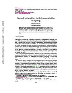
game, participants felt comfortable playing in different contexts, even at work (see Figure 13). 5.2.2. Playing Location A Friedman’s test revealed a significant effect in the answers for the “Where are you?” responses, could choose to ignore not pair-wise the notification, so we registered 193 answers for the (χ2(4)Participants = 57.0, p < 0.001). A post-hoc test or using Wilcoxon tests with Bonferroni correction in-app questionnaires (the ones included with the daily notifications). Due to the short length of the showed only significant differences for the “At home” answer and the rest of places (p < 0.001 for game, participants felt comfortable playing in different contexts, even at work (see Figure 13). three pairs). Where are you playing? # Sessions played
100 80 60 40 20 0 At home
At work
Other
On the move In a café
Figure 13. Total number of sessions played in a place. Figure 13. Total number of sessions played in a place.
5.2.3. User’s Perception A Friedman’s test revealed a significant effect in the answers for the “Where are you?” responses, end the evaluation, a System Usability ScaleWilcoxon (SUS) questionnaire [41] was answered by (χ2 (4)At= the 57.0, p