Aug 29, 1990 - of the signals are separated into packets with the same format. ...... as a token ring network or a circuit switched network with a packet-switched.
• IEEE
TRANSACTIONS
ON
COMMUNICATIONS.
VOL.
40.
NO. 9, SEPTEMBER
PREO,ED!NG P/_IGE BLANK PlOT FtL_._)
1992
/>'/
A Robust Yun-Chung
Coding
Chen,
Khalid
Scheme
Sayood,
Member,
IEEE,
for Packet and
Don
J. Nelson,
Video
Senior Member,
.J
.5
2-----
IEEE
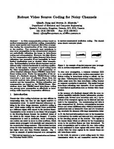
N 9 3 - 20 if7 /4/ Abstract--We present a layered packet video coding algorithm based on a progressive transmission scheme. The algorithm provides good compression and can handle significant packet loss with graceful degradation in the reconstruction sequence. Simulation results for various conditions are presented. I.
INTRODUCTION
UE to the rapid evolution the fields of ing and networking, video ininformation willimage be anprocessimportant part of tomorrow's telecommunication system. Up to now, video transmission has been mainly transported over circuitswitched networks. It is quite likely that packet-switched networks will dominate the communications world in the near future. Asynchronous transfer mode (ATM) techniques in broadband-lSDN can provide a flexible, independent and highperformance environment for video communication. Therefore, it is necessary to develop techniques for video transmission over such networks. The classic approach in circuit switching is to provide a "dedicated path," thus reserving a continuous bandwidth capacity in advance. Any unused bandwidth capacity on the allocated circuit is therefore wasted. Rapidly varying signals, like video signals, require too much bandwidth to be accommodated by a standard circuit-switching channel. With a certain amount of capacity assigned to a given source, if the output rate of that source is larger than the channel capacity, quality will be degraded. If the generating rate is less than the available capacity, the excess channel capacity is wasted. The use of packet networks allows for the utilization of channel sharing protocols between independent sources and can improve channel utilization. Another point that strongly favors packet-switched networks is the possibility that the integration of services in a network will be facilitated if all of the signals are separated into packets with the same format. Some coding schemes which support packet video have been explored. Verbiest and Pinnoo proposed a DPCM-based system which is comprised of an intrafield/interframe predictor, a nonlinear quantizer, and a variable length coder [1]. Their codec obtains stable picture quality by switching between three different coding modes: intrafield DPCM, interframe DPCM, and no replenishment. Ghanbari has simulated a two-layer conditional replenishment codec with a first layer based on hybrid DCT-DPCM and second layer using DPCM [2]. This Paper
approved
by
Communications March Flight The
29,
Editor
Society. 1991.
Center authors
Communication
the
This
under are
with
Lincoln,
NE,
68588.
IEEE
Log
Number
Communications
Manuscript work
Grant
and
for
was
received supported
by
Systems August the
of
29,
NASA
the
IEEE
1990;
revised
Goddard
Space
NAG5-916. the
Department
Information
Science,
of Electrical University
Engineering, of
Center
Nebraska-Lincoln,
9201526. 0090--6778/92503.00
for
scheme generates two type of packets: "guaranteed packets" contain vital information and "enhancement packets" contain "add-on" information. Darragh and Baker presented a subband codec which attains a user-prescribed fidelity by allowing the encoder's compression rate to vary [3]. The codec's design is based on an algorithm that allocates distortion among the sub-bands to minimize channel entropy. KJshino et al. describe a layered coding technique using discrete cosine transform coding, which is suitable for packet loss compensation [4]. Karlsson and Vertterli presented a sub-band coder using DPCM with a nonuniform quantizer followed by runlength coding for baseband and PCM with run-length coding for nonbaseband [5]. In this paper, a different coding scheme based on a progressive transmission scheme called Mixture Block Coding with Progressive Transmission (MBCPT) [6], [7] is investigated. Unlike the methods mentioned above, MBCPT does not use decimation and interpolation filters to separate the signals into sub-bands. However, it does have the attractive property of dealing separately with high frequency and low frequency information. This separation is obtained by the use of variable blocksize transform coding. This paper is organized as follows. First, some of the important characteristics and requirements of packet video are discussed. In Section III, the coding scheme called mixture block coding with progressive transmission (MBCPT) is presented. In Section IV, a network simulator used in testing the scheme is introduced. In Section V the simulation results are discussed.
Finally,
in Section
VI the paper
is summarized.
II. CHARACTERISTICS OF PACKET VIDEO The demand for various services, such as telemetry, terminal and computer connections, voice communications, and fullmotion high-resolution video, along with the wide range of bit rates and holding times they represent, provides an impetus for building a Broadband Integrated Service Digital Network (B-ISDN). B-ISDN is a projected worldwide public telecommunications network that will service a wide range of user needs. The continuing advances in the technology of optical fiber transmission and integrated circuit fabrication have been driving forces to realize B-ISDN. The idea of B-ISDN is to build a complete end-to-end switched digital telecommunication network with broadband channels. Still to be precisely defined by CCITT, with fiber transmission, H4 has an access rate of about 135 Mbps. Packet-switched networks have the unique characteristics of dynamic bandwidth allocation for transmission and switching resources, and the elimination of channel structure. They acquire and release bandwidth as needed. Because the video signals vary greatly in bandwidth requirement, it is attractive @
1992
IEEE
1492
IEEE TRANSACTIONS
to utilize a packet-switched network for video coded signals. Allowing the transmission rate to vary, video coding based on packet transmission permits the possibility of keeping the picture quality constant, by implementing "bandwidth on demand." There are three main merits when transmitting video packets over a 1) Improved are transmitted the coded bit
packet-switched network. and consistent image quality: If video signals over fixed-rate circuits, there is a need to keep rate constant, resulting in image degradation
accompanying rapid motion. 2) Multimedia integration: As mentioned above, integrated broadband services can be provided using unified protocols. 3) Improved transmission efficiency: Using variable bit-rate coding and channel sharing among multiple video sources, scenes can be transmitted without distortion if other sources, at the same time, are without rapid motion. However video transmission over packet networks also has the following drawbacks. 1) The time taken to transmit a packet of data may change from time to time. 2) Packets may be delayed constraints due to the human discarded.
to the point where, because of visual system, they have to be
3) Headers of packets may be changed because of errors and delivered to the wrong receiver. It has to be emphasized that the delay/lost effect can reach very high levels if the combined users' requirements exceeds the acquirable bandwidth and may seriously damage the quality of the image. When the signals transmitted in the network are nonstationary and circuit-switching is used with limited bandwidth, a buffer between the coder and the channel is needed to smooth out the varying rate. If the amount of data in the buffer exceeds a certain threshold, the encoder is instructed to switch into a coding mode that has lower rate but worse quality to avoid buffer overflow. In packet-switched networks, asynchronous time division multiplexing (ATDM) can efficiently absorb temporal variations of the bit-rate of individual sources by smoothing out the aggregate of several independent streams in the common network buffers [8]. To deliver packets in a limited time and provide a real time service is a difficult resource allocation and control problem, especially when the source generates a high and greatly varying rate. In packet-switched networks, packet losses are inevitable, but use of a packet-switched network yields a better utilization of channel capacity. However, it should be noted that the varying rate requirements of the video coder may not be synchronized with the variations in available channel capacity which changes depending on the traffic in the network. Therefore, the interactions between the coder and the network have to be considered and incorporated into the requirements for the coder. These requirements include the following. 1) Adaptability of the coding scheme: The video source we are dealing with has a varying information rate. So it is expected that the encoder should generate different bit rates by removing the redundancy. When the video is still, there is no need to transmit anything.
ON COMMUNICATIONS.
VOL. 40. NO. 9. SEPTEMBER
1992
2) Insensitivity to error: The coding scheme has to be robust to the packet loss so that the quality of the image is never seriously damaged. Remember that retransmission is impossible because of the tight timing requirement. 3) Resynchronization of the video: Because of the varying packet-generating rate and the lack of a common clock between the coder and the decoder, we have to find a way to reconstruct the received data which is synchronous to the display terminal. 4) Control coding
rate: Sensing
the heavy
traffic
in the
network, the coding scheme is required to adjust the coding rate by itself. In the case of a congested network, the coder could I-e switched to another mode which generates fewer bits with a minimal degradation of image quality. 5) Parallel architecture: The coder should preferably be implemented in parallel. That allows the coding procedure to be run at a lower rate in many parallel streams. In the next section, we investigate a coding scheme to see how well it satisfies the above requirements.
III.
MIXTURE
BLOCK
CODING
WITH
PROGRESSIVE
TRANSMISSION
Mixture block coding (MBC) is a variable-blocksize transform codi.'_g algorithm which codes the image with different blocksizes depending upon the complexity of that block area. Low-complexity areas are coded with a large blocksize transform coder while high-complexity regions are coded with small blocksize. The complexity of the specific block is determined by the distortion between the coded and original image when the same number of bits are used to code each block. A more complex image block has higher distortion. The advantage of using MBC is that it does not process different complex regions with the same blocksize. That means MBC has the ability to choose a finer or coarser coding scheme to deal with different complex parts of the same image. With the same rate, MBC is able to provide an image of higher quality than a coding scheme which codes different complex regions with the same blocksize coder. When using MBC, the image is divided into maximum blocksize blocks. After coding, the distortion between the reconstructed block and the original block is calculated. The block being processed is subdivided into smaller blocks if that distortion fails to meet the predetermined threshold. The coding-testing procedure continues until the distortion is small enough or the smallest blocksize is reached. In this scheme, every block is coded until the reconstructed image is satisfactory and then moves to the next block. Mixture block coding with progressive transmission (MBCPT) is a coding scheme which combines MBC and progressive coding. Progressive coding is an approach that allows an initial image to be transmitted at a lower bit rate which can later be updated [9]. In this way, successive approximations converge to the target image with the first approximation carrying the "most" information and the following approximations enhancing it. The process is like focusing a lens, where the entire image is transformed from low-quality into high-quality. In progressive coding, every
CHEN
ctal.:
CODING
SCHEME
FOR
PACKET
VIDEO
I.,193
Block _--
a_burrer
,_
.........
0
add
.........
overhead
L
add
I
I
overhead
to
buffer t
to
with
decreaslnl[
buffer ..................
goes down psss B x
to 6
priority
1 with 2x2
Fig.
1.
Structure
of
the
first
pass
consisting
of
16
x
lG
blocks
for
lowest priority
MBCPT.
pixel value, or the information contained in it, is possibly coded more than once and the total bit rate may increase due to different coding scheme and quality desired. Because only the gross features of an image are being coded and transmitted in the first pass, the processing time is greatly reduced for the first pass and a coarse version of the image can be displayed without significant delay. It has been shown that it is perceptually useful to get a crude image in a short time, rather than waiting a long time to get a clear complete image. With different stopping criterion, progressive coding is suitable for dynamic channel capacity allocation. If a predetermined distortion threshold is met, processing is stopped and no more refining action is needed. The threshold value can be adjusted according to the traffic condition in the channel.
Fig. 2.
18
from the first pass in a short time and the data from following passes serve to enchance it. Fig. 1 shows the structure of a pass consisting of 16 x 16 blocks for MBCPT. Fig. 2 shows the parallel structure of MBCPT. Coding algorithms using quad trees have also been proposed by Dreizen [10] and Vaisey and Gersho [11]. In the quad tree coding structure of this paper, the 16 x 16 block is coded and the distortion of the block is
t8
Bx8
4
Successive approximations (or iterations) are sent through the channel in progressive coding and lead the receiver to the desired image. If these successive approximations are marked with decreasing piority, then a sudden decrease in channel capacity may only cause the received image to suffer from quality degradation rather than total loss of parts of the images. MBCPT is a multipass scheme in which each pass deals with different blocksizes. The first pass codes the image with maximum blocksize and transmits it immediately. Only those blocks which fail to meet the distortion threshold go down to the second pass which processes the difference image block (coming from the original and coded image obtained in the first pass) with smaller blocks. The difference image coding scheme continues until the final pass which deals with the minimum size block. At the receiving end, a crude image is obtained
x
Parallel structure for MBCPT.
X
4
2x2
Fig. 3.
Example of the quad tree structure.
enough for ease of processing and storage requirements, but large enough to limit the inter-block redundancy [12]. Large blocksizes result in higher compression, but it is very difficult to build real-time hardware for blocksizes larger than 16 x 16 because of the increase in the number of computations. So, 16 x 16 is chosen to be the largest blocksize. The minimum blocksize determines the finest visual qualtiy that is achievable in the busy area. If the minimum blocksize is too large, it is possible to observe the blockiness in the coded edge of spherical objects because the coding block is square. In order to match the zonal transform coding used
calculated. If the distortion is greater than the predetermined threshold for 16 x 16 blocks, the block is divided into four 8x 8
in this paper, 2 x 2 is the smallest blocksize and there are four passes (16 x 16, 8 x 8, 4 x 4, 2 x 2) in this scheme. Figs. 4-7 shows images from the 4 passes. After applying the discrete cosine transform, only four coefficients, including the de and three lowest order frequency coefficients, are coded and the others are set to zero. The de
blocks for additional coding. is continued until the only threshold are those of size 2 The blocksize used in the
coefficient in quantizer due gray level for de coefficient
This coding-checking procedure image blocks not meeting the x 2. Fig. 3 shows the algorithm. coding scheme should be small
the first pass is coded with an 8-bit uniform to the fact that it closely reflects the average that image block and is hard to model. The in the subsequent passes follows a Laplacian
-
1494
IEEE
Fig.
4.
Inlclg¢
rccon,truutud
tn+m
tir,,t
pct_,',.
TRANSACTIONS
ON
Fig.
7.
COMMUNICATIONS,
Image
VOL.
reconstrucied
from
x x
IB
Fi_.
5.
[m_c
rcc.on,truc'_cd
trom
Tir-t
t_'.o
pzk_r,¢_,.
overheed
Fig.
8,
=
Overhead
x
40. NO.
four
9. SEPTEMBER
1992
passes.
x x
18
1.i001,1001,1001.I001,1001
assignment
and
zonal
coding,
the difference image coming from the current frame and the previous frame which is locally decoded from the first three pass data. Fig. 9 shows the algorithm of this coder. Fig. 10 shows a different scheme which does the local decoding with all four passes. From Fig. 11, it can be seen that when there is no packet loss, the performances of these two schemes are
Fig.
6.
Im:l_e
rcc_n',_ruc_cO
lr,ma
tSr,,t
three
p:r, scs.
model, and a 5-bit c_ptim:d Lapl:lcian nonuniform quantizer is used to code it. The ac coefficients also follow a Laplacian model with a variance greater than that of the dc coefficient and can therefore also be coded using a Lpl,'lcian quantizer. As an alternative, an LBG _ cct_ar qu:mtizcr with a 512 codebook size is used to qu:mtize _he vector ,.,.hich comprises the three. ac coefficient. The initial threshold of e:_ch pass is selected beforehand and is rcadjus_able during the operation according to the channel condition and quality required. Because only partial blocks ,.vhich fi6] to meet the distortion threshold need to bc c_._ded,side information is needed to instruct the receiver _n ht_w to reconstruct bit of overhead is nccdcd for each block.
the image. One If a block is to
be divided, a I is a._,iL_,ncd to hc it_ w, erhcad; if not, a 0 is assigned. The cx;Jmplc _,hov, n in Fig. S has the following overhead: 1. lll(ll, l(l(Jl. 1_1_1.1()_)1. l_i{_l. The interframc c¢_dcr u,,cd in thi_, p:tI_cr is a differential scheme which is t_;r_cd on 3,1[3C1"I- This coder processes
quite the same. But when congestion occurs in the network, with the priorities assigned to packets, packets from pass 4 are expected to be discarded first. In this case, the performance (from Fig. 12) of the scheme in Fig. 9 is much better than the one in Fig. 10. Therefore the coding scheme in Fig. 9 is used in our simulation. In this paper, the Kronkite motion sequence from the use database with 16 frames is used as the simulation source. Every image is 256 x 256 pixels with graylevels ranging from 0 to 255. It is similar to a video conferencing type image which has neither rapid motion nor scene changes. Due to this characteristic, advanced techniques like motion detection or motion compensation have not been used but could be implemented when broadcasting video. From the datastream output that is listed in Table I, we can see that the data in pass 4 represents 30-40% of the entire data. This part of the data is involved in increasing the sharpness of the image and is usually labeled with the lowest priority in the network. We therefore call this the least significant pass (LSP). With a substantial possibility of being discarded due to low priority, those packets from pass 4 will not be used to reconstruct the locally decoded image and be stored in the frame memory. This prevents the packet loss error propagating into following frames if the lost packet belongs to pass 4.
CHiN
et al,:
CODING
SC}tEME
FOR
PACKET
VIDEO
L495
Video in
40 LSg MSP
_g.5
CHANNEL
39 I
38.5
1
B
38
37.5
37 local decoding Local decoding
38.5
Coder
I 2
36
I 4
I 6
with all 4 passel with first 3 paeaes
1 8
I I0
I 12
f 14
16
FRAME
Fig.
11.
Performance
of
two
differential
MBCPT
schemes
without
packet
loss. 14S_
outVide°
'°t
39,5 Decoder
Fig. 9.
_ O'--O
Local Local
decoding decoding
with with
all 4 passes first 3 passes
3gd[
Differential MBCPTcoding scheme (1).
_"xl3.- "Q,,\ 38,5
Video in
38
x_
/Q, _
J13"-,.13._
" ",13..-l_-
43"
q3"-
"O-.
B/.
_.
\
_
CHANNEL
_
37.537 38.5
r 38
I 2
I 4
I 6
I §
I 10
I 12
I 14
18
r;tAUE
Fig. 12. Performance of the two MBCPT schemes with packet losses from pass 4. Coder
the existing capacity and reliability of system components. The scheme for communicating information regarding the operating status is called the system protocol. Since the communication of system information must flow through the channel, it reduces the overall capacity of the physiVideo out
Decoder
Fig. 10. Differential MBCPT coding scheme (2). IV. SIMULATION NETWORK The network simulator
used for this study was a modified
version of an existing simulator developed by Nelson et al. [13]. A brief description of the simulator is provided here.
cal layers, but hopefully provides a more efficient system overall. Therefore, system efficiency depends entirely upon these protocols, which, in turn, depend upon the system topology, communication channel properties, nodal memory and component reliability. Most network protocols have been developed to provide high reliability in topological structures with reasonably high channel reliability. In order to fit into the purpose of this study, most modifications which were made to the simulator were in those modules concerning the network layer. Since the simulator is structured in modules which represent, to some degree, the ISO Model for packet switched networks, a more detailed description about the network layer modules follows.
A. Introduction As mentioned in Section lI, tomorrow's integrated telecommunication network is a very complicated and dynamic structure. Its efficiency requires sophisticated monitoring and control algorithms with communication between nodes reflecting
B. The Network Layer and Basic Operation The simulation of a layer at each node is represented by a "processor" and one or more "packet queues." All events are scheduled through the "Sim_Q" which drives the simu-
1496
IEEE TRANSACTIONS
TABLE I PERFORMANCE DEGRADATIONDUE TO PACKET LOSS IN DIFFERENT PASSES PSNR with packet Frame
#
losses
only in
Pass 4
Pass 3
Pass 2
Pass
0 1 2 3 4 5 6 7 8 9 10 11 12
40.30 40.59 40.07 39.70 40.19 39.65 38.74 38.59 38.68 38.51 39.48 39.26 38.83
40.30 40.37 39.02 38.19 38.35 38.05 36.27 35.58 34.96 34.33 34.31 34.01 33.75
40.30 40.12 36.15 35.82 36.31 35.21 33.23 31.52 30.81 29.85 29.86 29.67 29.57
40.30 37.55 31.99 31.70 30.18 28.35 26.07 24.61 23.27 21.77 21.54 21.90 22.00
13 14
38.54 38.86
33.09 33,21
29.46 29.52
22.30 22.34
15
39,47
33.24
29.37
22.33
1
lator. Initially, the processors are all idle, the packet queues are all empty and the only tasks scheduled are the arrival of messages at the various nodes. The simulator operation occurs by examining the next event and performing the task indicated. The task may result in the scheduling of additional events, generally referred to as task completion times. When a message or packet is placed in the input queue at a node for a given layer, the processor for that queue is marked as busy, the packet is removed from the queue, and the task to be performed by the processor is scheduled for completion. When the task is completed (as a result of the simulator reaching that point in time), the "processor" examines the queue. If the queue is empty, the processor is set idle; otherwise it removes the next message or packet from the queue and schedules the completion of the operation which must be preformed. The layers in the simulator are quite close in operation to the ISO transport, network and datalink layers. 1) The Session Layer: In the OSI model, the session layer (SL) allows users to establish "sessions" on local or remote systems. In the simulator, as mentioned above, it contains a relatively simple model of the subscribers, participates in flowcontrol, and acts as a statistics coUector for messages arriving and delivered. At message arrival time (from Sire_Q), the session layer generates the "message" with all of its randomly selected attributes and if flow control or node hold-down are not in effect, submits it to the transport layer. It then schedules the next message arrival time. During initialization, the task "SL_Rcv_Msg" for each node is queued in Sim_Q for the arrival time of the first message at that node. When this task is executed by the simulator, a message packet is generated and placed in the transport queue. The arrival of the next message is then queued in Sim Q with the same task and with an arrival time determined by the random number generator (Poisson Distributed). The only other task performed by the session layer is the "SL_Snd Msg" task that simulates delivery of mesages to the subscribers, develops message statistics and "cleans up" the queues for messages delivered. 2) The Transport Layer: The basic function of the transport
ON COMMUNICATIONS,
VOL. 40, NO. 9, SEPTEMBER
1.992
layer at the sending end is to receive the message from the session layer, place it in packets and pass the packets on to the network layer. At the receiving end, the packets are reassembled into a message for delivery to the session layer. To accomplish the complex task of assuring reliable delivery, there is a transport time-out mechanism at both the sending and receiving nodes and a message acknowledgement packet that is sent to the sending node when all packets for the message have been satisfactorily received. At the sending end, if a message acknowledgment is not received in the allotted time period, the message can be retransmitted. In the simulations reported in this paper, the retransmission feature was not used. At the receiving end, if all packets are not received in the specified period of time, the entire message is discarded. It is recognized that in some networks, packetization takes place at the network level, leaving the transport layer responsible only for messagelevel structures. Reassembly, depending upon the protocol, can take place as low as the datalink level. These tasks were both placed in the transport layer, but are modular, and could be extracted and placed elsewhere. Also, the simulator was originally designed for datagram service, and since the packets do not necessarily arrive in order, it is unlikely that assembly would take place at the datalink level. 3) The Network Layer: The ne_'ork layer is concerned with controlling the operation of the network. A key design issue is determining how packets are routed from source to destination. Another issue is how to avoid the congestion casued when too many packets are presented to the network at the same time. In the simulator, the network layer performs all of the functions related to these two aspects with the exception of that aspect of flow control which takes place at the session layer, and the recovery protocols which require some service from the datalink layer. It also activates new channels when needed and determines when packets originating at other nodes are to be discarded. The network layer is currently the most dynamic with regard to the coding of modules. Five modules currently comprise the network layer. These include relatively static modules; one module for capturing lines or channels when more capacity is required and releasing them when they are not needed; one module for the network processor and queue handling and one module for the routines which are common to most routing algorithms. This leaves two modules for the dynamic parts of the routing and flow control algorithms. 4) The Datalink Layer: The main task of the datalink layer is to take the raw transmission faciity and transform it into a line or channel that appears free of transmission errors to the network layer. It simulates the sending of the message over the channel and the delivery at the other end. When a packet is received, the datalink acknowledgment is initiated either by the piggy-back acknowledgment or by generating a datalink ackowledgment packet. As mentioned previously, the datalink level also simulates the physical layer on a statistical basis. (Entered bit eror rates are used in conjunction with a random number generator to determine if messages are corrupted.) When a line is "brought up," used to establish initial connections. Also, down," packets
health packets are when a line "goes
an active node will immediately issue health check to ascertain when the channel is again available.
i.
F "-_
CItEN
¢t M.:
CODING
SCHEME
FOR
PACKEI"
I--
_'_
"1'_
.......
-....
VIDEO
C. Modifications
I497
A. Packetization
A major problem of using this system as a simulation tool for the study of packet video is that as initially designed the system did not actually transmit messages from node to node. While a "packet" carrying all the necessary describing information moved from node to node, there was no actual data in the packet. Therefore, modifications had to be made to the simulator to accommodate the video data. In the sending node, a field called "Image" which contains real image data is attached to the record "Packet_Ptr" allocated to the message generated in the session layer. There are three new modules in this layer. First, "Get Image" puts the image data into the
The task of the packetizer
is to assemble
video information,
image field of a message generated at a specific time and node. Second, "ImageAvailable" checks to see if there is any image data that still need to be transmitted. If that is
coding mode information, if it exists, and synchronization information into transmission ceils. In order to prevent the propagation of the error resulting from the packet loss, packets are made independent of each other and no data from the same block or same frame is separated into different packets. The segmentation process in the transport layer has no information regarding the video format. To avoid the bit stream being cut randomly, the packetization process has to be integrated with the encoder, which is in the presentation layer of the users's premise. Otherwise, some overhead has to be added into the datastream to guide the transport layer to perform the packetization in the desired manner. In order to limit the delay of packetization, it is necessary to stuff the last cell of a packet
true, the following message, generated at that specific node, is still the image message and contains some image data. Third, "Receive linage" collects the image data in the session layer of the receiving node when the flag "Image_Complete" is on. In module " Session " " " different priorities are asMs_,, Arnve,
video with dummy bits if the cell is not completely full. Every packet must contain an absolute address which indicates the location of the first block it carries. Because every block in MBCPT has the same number of bits in each pass, there is no need to indicate the relative address of the following
signed to different messages. In module "Session_Msg_Send," some statistics are calculated including the number of lost image packets and the transmission delay for image packets. In the original design, the transport layer simply duplicated the same packet with different assigned sequential packet numbers without actually packetizing the message. The module "Transport_Packetize" has been modified to really packetize the image data which resides in the message record queued in "Transport Q" when it is called. The module "Transport Reassemble" is called to reassemble these image packets according to their packet number when the flag ''Im-
blocks contained in the same packet. There always exists a tradeoff between packaging efficiency and error resilience. If error resilience is considerable, one packet should contain a smaller number of blocks. However, since each channel access
age Content" defined in "Packet _Ptr" is true. The network layer is responsible for routing and flow-control. This module was already very well developed, so the modifications to be performed here were relatively minor. In the datalink layer, in order to simulate the delivery of packets through the channel, a new packet is generated at the receiving node and the information including the image data from the transmitted packet (which will still be resident at the sending node) are copied into it. Using existing bit-error-rates, the transmission success rate can be set and bit errors can be inserted in both the data and control bits in the packet. Errors in the control bits are simulated separately as long as the error rates are consistent. If an error in the control bits occurs, the transmission is assumed to fail and retransmission on the threshold of the timeout
will occur, again depending number. In addition to the
modifications made to the layer modules, we had to arrange some new memory elements allocated for image messages and packets. In order to make sure the simulation is run in the steady state, the image data is made available to the network after some simulaton time has passed.
V. INTERACTION OF THE CODER AND THE NETWORK When the video data network, some problems following section.
is packed and sent into a nonideal emerge. These are discussed in the
by a station contains overhead, the packet length should be large for transmission efficiency. Fixed length packetization is used in this paper for simplicity. Because of the structure of the coding scheme, the packets are classified into four priorities, with the packets from the first pass classified as the highest priority packets, and the packets from the fourth pass as the lowest priority packets. This priority assignment also reflects the importance of the various packets to the reconstruction of the image sequence at the receiver. Table I shows the effect of approximately the same number of packets lost in each pass on the reconstructed error in the received sequence.
B. Error Recovery There is no way to guarantee that packets will not get lost after being sent into the network. Packet loss can be mainly attributed to two problems. First, bit errors can occur in the address field, leading the packets astray in the network. Second, congestion can exceed the networks management ability and packets are forced to be discarded due to buffer overflow. Effects created by higher pass packet loss (like pass 4) in MBCPT coding will be masked by the basic passes and replaced with zeros. The distortion is almost invisible when viewing at video rates because the lost area is scattered spatially and over time. However, loss of low pass packets (like pass 1), though rare due to high priority, will create an erasure effect due to packetization and the effect is very objectionable. Considering the tight time constraint, retransmission is not feasible in packet video. It may also result in more severe congestion. Thus, error recovery has to be performed by the decoder alone. In our differential MBCPT scheme, the packets from pass 4 are labeled lowest priority and form a great part
! IEEE TRANSACTIONS
1498
!
ON COMMUNICATIONS.
VOL. ,tO, NO 9, SEPTEMBER
TABLE II NUMBER OF BITS TRANSMI'VI'EDFOR EACH PASS AND THE TOTAL NUMBER OF BITS TRANSMrFrED FOR EACH FRAME
i
Frame
Overhead
Pass I
Pass2
Pass3
Pass4
Total
1
2588
4352
8400
24248
24416
64004
I
32 4 5 6
2156 1772 2088 2164 1988
4352 4352 4352 4352 4352
7168 5992 6888 7112 6328
19432 15232 18760 19600 17920
20104 11312 13216 17416 14336
53212 38660 45304 50644 44924
I
7 8 9 10
2352 2432 2316 2568
4352 4352 4352 4352
7448 7952 7504 7840
21896 22512 21336 24528
22736 25704 24136 26992
58784 62952 59644 66360
I
12 11 13 14 15
2352 1892 1968 2468 2216
4352 4352 4352 4352
7616 6048 6384 7840 9352
21728 16856 17584 23128 18088
18200 11144 15008 26936 728
54248 40292 46296 64734 34736
16
I I I I
I992
1496
4352
Total
34816
69632
Mean
2176
4352
Deviation
290
4536 114408
0
36164 820992
19729
17962
51312
1094
3179
7000
10395
congestion and will not cause too much degradation in quality. The erasures caused by basic pass loss are simply covered with the reconstructed values from the corresponding area in the previous frame. This remedy seems insufficient even when there is only a small amount of motion in that area. Motion detection and motion compensation could be used to find a best matched area for replacement in the previous frame. Side information in the MBCPT decoding scheme is very important. So, this vital information is not allowed to get lost. Two methods can be used for protection. First, error control coding, like block codes or convolutional codes, can be applied in both directions along with and perpendicular to the packetization. The former is for bit error in the data field while the latter is for packet loss. The minimum distance that the error control coding should provide depends on the network's probability of packet loss, correlation of such loss and channel bit error rate. Second, from Table II, we can see that the output rate of side information and pass 1 and even pass 2 is quite steady. It seems feasible to reserve a certain amount of channel capacity to these outputs to ensure their timely arrival. That means circuit-switching can be used for important and steady data.
Flow
12936 287392
7150
of the total data. These packets can be discarded whenever network congestion occurs. That will reduce the network
C.
12824 315672
Control
In order to shield the viewer from severe network congestion, there are some flow control schemes which are considered useful. It there is an interaction between the encoder and the transport layer, then the encoder can be informed about the network condition. Depending on that, the encoder can adjust its coding scheme. In the MBCPT coding scheme, if the buffer is getting full, that means that the bit generating rate is overwhelming the packetization rate and the encoder will switch to a coarse quantizer with fewer steps or loosen the
threshold
to decrease
its output rate. In this way, smooth
qual-
ity degradation is obtainable. However, this also complicates the encoder design. It is possible to use the congestion control of the network protocols to prevent drastic quality change by assigning different priorities to packets from different passes. Ignoring the relative importance of each packet and discarding packets blindly sometimes brings disaster and can cause a session shut down. For example, if the side information gets lost it can have a severe impact on the decoding process. In the MBCPT coding scheme, side information and packets from pass 1 are assigned highest priority and higher pass packets are assigned with decreasing priority. D. Interaction
with Protocols
In the ISO model, physical, datalink and network layers comprise the lower layers which form a network node. The higher layers have transport, session, presentation and application layers and typically reside in a customer's premises. The lower layers have to do nothing about the signal processing and only work as a "packet pipe." The physical layer requires adequate capacity and low bit error rate which are determined only by technology. The datalink layer can only deal with link-management because all the mechanics, like requesting retransmission, are not feasible in packet video transmission. The network layer has to maintain orderly transmission by deleting the delay jitter with input buffering. Otherwise, it can take care of the network congestion by assigning transmission priority. As the higher layers reside in the customer's premises, it performs all the functions of the packet video coder. The transport layer does the packetization and reassembly. The packet length can be fixed or variable. Fixed packet length simplifies segmentation and packet handling while a variable packet length can keep the packetization delay constant. The
CHEN
er al.:
CODING
SCHEME
FOR
PACKET
1499
VIDEO
[
?0 4O 80
i"
f
It i
,, I_
so ,
I',
40
,-',.
/
l
,-,
"l
ii
•
,I
\
•
I
%'
\
•
I
.'!8
Overhead
........ ...... .....
30
34
\,
_oI_,,,
+
PIss
4- Pass
|
Pall 3 Pe** 4 Total
2
.",
_-, ..............
_
.'_
\'..."_
I
"-_ \"-
i
32 t 0.4,
1
I
O.B
0.8
I
I
1
I
I
)
1.2
1.4
1.8
1,8
output
Fig.
13
PSNR
versus
video
o I
I 2
output
rate
(video
transmission
at 30
PERFORMANCE RESULTS
as
E (255)2 =
101ogzo y_
(Xlj
_
Fig.
i
t
_
i
i
B
8
10
12
14
Data
rate
BIT RATE FOR EACH
PASS
frames/s).
per pixel, which results in a bit rate of 15.3 Mbits/s, given a video rate of 30 frames/s. As Table II shows, the average data rates of our system is 1.539 Mbits/s. The compression rate is about 10 with a mean PSNR of 38.74 dB where PSNR
PSNR
_ 4
I
'"
16
FP, AM £
Results obtained in this packet video simulation show that substantial compression can be obtained while maintaining high image quality through the use of this differential MBCPT scheme. The monochrome sequence used in this simulation contains 16 frames, each of size 256 x 256 pixels with 8 bits
is defined
2
rateOlblts/sec)
session layer supervises set-up and tear-down for sessions which have different types and quality. There is always a tradeoff between quality and cost. The quality of a set-up session can be determined by the threshold in the coding scheme and the priority assignment for transmission. Of course, the better the quality, the higher the cost. Fig. 13 shows the tradeoff between PSNR and video output rate by adjusting thresholds. The presentation layer does most of the signal processing, including separation and compression. Because it knows the video format exactly, if any error concealment is required, it will be performed here. The application layer works as a boundary between the user and the network and deals with all the analog-digital signal conversion. VI.
T
2.2
'r_J) 2
Fig. 14 shows the data rate of sequence frames with side information, 4 passes and total rate. It is clear that the data rate of pass 1 is constant as long as the quantization mode remains the same. Side information and data from pass 2, even pass 3, is also relatively constant (Table III). The data rate of pass 4 is bursty and are highly uncorrelated. As pass 4 data is not essential to the reconstruction of the image, the rate profiles as shown in Fig. 14 and Table I suggest the use of a reserved channel of some sort for passes 1-3 and the side information, and perhaps a more unreliable channel for pass 4 data which comprises more than 30% of the total traffic. Such a situation can be accommodated in a variety of systems such
14.
of
simulation
TABLE OUTPUT
CALCULATED VALUES
WITH 30 ARE
THE
RESPECTIVE ENCODE
Mean Deviation
INSTA,',n'ANEOUS
A PARTICULAR
Overhead
65.28 8.70
VIDEO
AND
Pass
130.56 0.00
1
RATI:.
RATES,
MINIMUM
FRAME
IN THE
Pass
fames.
Ill
AND THE TOTAL
FRAMF.S/S
MAXIMUM
sequence
BIT RATE.
THE WHICH
SEQUENCE.
Pass
RATES
THE
3
WERE
AND MINIMUM
CORRESPOND
OF BITS
NUMBER
2
THE
MAXIMUM
TO
NEEDED
THE
TO
UNIT
IS KILOBITS.
Pass
4
Total
214.50
591.87
538.86
32.82
95.37
210.00
1539.36 311.85
Maximum
77.04
130.56
280.56
735.84
821.52
1990.80
Minimum
44.88
130.56
136.08
384.72
21.84
1042.08
switched
network
as a token ring network
or a circuit
with a
packet-switched overlay. Fig. 15 shows the PSNR for each frame in the sequence. Notice that the standard deviation of the PSNR is only 0.2 dB, which implies a substantial uniformity of quality, at least in terms of objective performance measures. If constancy with regard to some subjective criterion is desired, it would be necessary to incorporate this in the determination of the thresholds and the decision mechanism for the quad tree. In the simulation, the same threshold has been used throughout the sequence. If further flexibility, say for higher visual quality, is desired, a varying threshold can be used for different frames. That may generate a more variable bit rate. From the difference images of this sequence, frames 1-8 seem quite motionless while frames 9-13 motion. We adjusted the traffic condition
contain substantial of the network to
force some of the packets to get lost and thus check the robustness of the coding scheme. Heavy traffic was set up in the motionless and motion period separately. The average packet loss percentage was 3.3%, which is considered high for most networks. Fig. 16 shows images which suffered packet losses from pass 4. As can be seen, the effect of lost packets is not at all severe, even if the lost packet rate is unrealistically high. This is because of the performance from the first three passes is relatively good and the packet from the fourth pass is not essential for reconstruction. Fig. 17 shows the case when packet loss occurs in pass 1. Clearly there are visible defects in the motion period. Further, the
1500
IEEE TRANSA(TIONS
ON Ct)M_.RNICA['It)NS.
VOI. 4(k NO. 9. SEPTEMBER
1992
4O
.....•.............. ........._
39
38
:37
(a) 36 _:
4
6
8
io
12
14
18
FP,.a.M E Fig
15
PSNR
of simulalion
_cquence
frames.
(b) Fig,
Ia I
I I (b)
!
Fig.
16.
(a) The effect of pass 4 packet lo'_sh_r frame 4. (b) The effect of pass 4 packet loss for frame 10.
I
error will propagate to the following frames. Apparently, the replenishing scheme used here is not sufficient in areas with motion. It is bctie'.ed that this inconsistencv can be eliminated
I
with a motion compensau_r algorithm which would find the appropriate area for replenishment and error concealment which limits the propagation of error.
of pass l packet loss for frame pass 1 packet loss for frame 9.
3. (b) The effect
of
described and requires a flexibility v,hich is not possible in a circuit-s`.`.'itched network. With all the requirements for applying packet video in mind, MBCPT has been investigated. It is found that MBCPT has appealing properties, like high compression rate with good visual performance, robustness to packet lost, tractable integration with network mechanics and simplicity in parallel implementation. Some additional considerations have been proposed for the entire packet video system, like designing protocols, packetization, error recovery and resynchronization. For fast moving scenes, the differential MBCPT scheme seems insufficient, blotion compensation, error concealment of even attaching function commands into the coding scheme are believed to be useful tools to improve the performance and ',,,'ill be the direction of future research. REFERENCES [l]
[2]
CONCLUSION
The network simulator was used only as a channel in this simulation. In fact, before the re:tl-time processor is built, a lot of statistics can be collcctcd from the network simulator to improve upon the coding scheme. These include transmis-
(a) The effect
sion delays and losses from various passes under different network loads. For resynchronization, the delay jitter between received packets can also be estimated from the simulation. The environment for tomorrow's telecommunication has been
[3] VII.
17.
[4]
[5]
W. Verbiesl and L. Pinnoo, "A variable bit rate codec for asynchronous transfer mode networks," IEEk J. Select. Areas Commun., vol. 7, pp. 761-770. June 19S9. M. Ghanbari, "Two-la.,.er coding of video signals for VBR networks," IEEE J. Select. Areas Commun., vol. 7. pp 771-781, June 1989. J. Darragh and R. Baker, "Fixed distortion subband coding of images for packet-switched networks," IEEE J. Select. Areas Comrmm., vol. 7, pp. 789-800, June 1989. F. Kishino, K. Manaabe, Y. Hayashi. and H. Yasuda, "Variable bitrate coding of video signals for ATM networks," IEEEJ. Select. Areas Commun., vol. 7, pp. 801-806. June 19S9. G. Karlsson and M. Vcllerli, "'Packet video and its integration into network architecture." IEEEJ. Select. An'as Comm,n., vol. 7, pp. 739-751,
CHEN
ez
al.:
CODING
SCHEME
FOR
PACKET
1501
VIDEO
June 1989.
V
r
r i
M.C. Rest. "Data compression using adaptive transform coding," Ph.D. dissertation, Univ. Nebraska-Lincoln, 1988. [7] M.C. Rest and K. Sayood, "A progressive data compression scheme based on adaptive transform coding," in Pro