... and the classical 4th-order RungeâKutta time-integration scheme with sym- ...... 8100. ⢠to increase the understanding of physical mechanisms of coherent- ...
Applied Scientific Research 59: 353–377, 1998. © 1998 Kluwer Academic Publishers. Printed in the Netherlands.
353
A Robust High-Resolution Split-Type Compact FD Scheme for Spatial Direct Numerical Simulation of Boundary-Layer Transition MARKUS J. KLOKER Institut für Aerodynamik und Gasdynamik der Universität Stuttgart, D-70550 Stuttgart, Germany
Abstract. In this paper an efficient split-type Finite-Difference (FD) scheme with high modal resolution – most important for the streamwise convection terms that cause wave transport and interaction – is derived for a mixed Fourier-spectral/FD method that is designed for the spatial direct numerical simulation (DNS) of boundary-layer transition and turbulence. Using a relatively simple but thorough and instructive modal analysis we discuss some principal trouble sources of the related FD discretization. The new scheme is based on a 6th-order compact FD discretization in streamwise and wall-normal direction and the classical 4th-order Runge–Kutta time-integration scheme with symmetrical final corrector step. Exemplary results of a fundamental-(K-) type breakdown simulation of a strongly decelerated Falkner–Skan boundary layer (Hartree parameter βH = −0.18) using 70 mega grid points in space are presented up to the early turbulent regime (Reθ,turb ≈ 820). The adverse pressure gradient gives rise to local separation zones during the breakdown stage and intensifies final breakdown by strong amplification of (background) disturbances thus enabling rapid transition at moderate Reynolds number. The appearance and dynamics of small-scale vortical structures in early turbulence basically similar to the large-scale structures at transition can be observed corroborating Kachanov’s hypothesis on the importance of the K-regime of breakdown for coherent structures in turbulence. Key words: boundary-layer transition, spatial direct numerical simulation, modal resolution characteristics of discretization, new split-type scheme, coherent structures.
1. Introduction The understanding of the formation and dynamics of coherent structures in spatially developing transitional and turbulent boundary layers is still a great challenge in fluid dynamics research. Spatial direct numerical simulation is arguably the most promising tool to gain more insight into the complex unsteady flow fields. However, high wave transport accuracy of the numerical method is required for reliable results – a definite fact in transition research based on physics. While the Fourier spectral method is perfectly suited in this respect and therefore always used for spatially periodic and occasionally for special spatially growing problems (requiring then basically many Fourier modes and an elaborate window function that artificially renders the flow field streamwise periodic (see, e.g., [1]) it is rela-
354
M.J. KLOKER
tively unflexible in cases of strong local flow or geometry variations. For the more flexible FD methods on the other hand, the required accuracy can hardly be met by solely refining the grid using customary robust standard schemes, and the use of advanced schemes with improved wave resolution qualities at safe numerical stability is essential. In this paper we use a relatively simple but thorough and instructive modal analysis to bring out the principal trouble sources of FD discretization (in space, cf. [2], and time) on the basis of the linear scalar advection/diffusion equation. Section 2.1 deals with the advection or convection term, that is the main problem source; in Section 2.2, the second derivative is briefly discussed; the section is closed by summarizing the verification and practical DNS experiences. Finally, in Section 3 some exemplary results of a transition simulation using the new scheme are presented. 2. FD Methods: Localization of Principal Problems Using 1-D Modal Analysis 2.1. F IRST
DERIVATIVE
2.1.1. Basics of spatial discretization The considered function φ(x) is spatially periodic: φ = exp(ikx) = exp(ik ∗ n);
k ∗ = k1x, real;
n = x/1x;
0 ≤ n ≤ N, (1)
where k ∗ is the non-dimensional wave number (0 ≤ k ∗ ≤ π ) and k ∗ = π is the wiggle mode (λ = 21x). FD formulae for the first derivative of this function can, by plugging Equation (1) into the respective formula, be rearranged to ∗ /1x)φ, φ 0 = (ikmod
(2)
∗ is the modified wave number which is complex in general (exact: where kmod ∗ kmod = k ∗ , real). The stencil given in Table I yields: ∗ = (1/q) · (1/(Fr2 + Fi2 )) · {Kr Fr + Ki Fi + i(Ki Fr − Kr Fi )}, kmod
(3a)
Kr = (e − c) sin(k ∗ ) + (f − b) sin(2k ∗ ) + · · · ,
(3b)
Ki = −d − (e + c) cos(k ∗ ) − (f + b) cos(2k ∗ ) − · · · ,
(3c)
Fr = β + (α + γ ) cos(k ∗ ) + (δ + ε) cos(2k ∗ ) + · · · ,
(3d)
Fi = −(α − γ ) sin(k ∗ ) − · · · .
(3e)
∗ ∗ (k ∗ ) for central FDs (kmod purely real) of different Figure 1a shows the curves kmod order, where the order is maximum for the given stencil, respectively. Compact FDs follow the exact line much longer than standard FDs, but common is a respective
SPATIAL DIRECT NUMERICAL SIMULATION
Table I. Finite-Difference formulae for first and second derivative (80 , 800 ) with constant grid spacing 1, xn = n1x; δ, α, β, γ , ε contain derivatives at (n − 2), (n − 1), (n), (n + 1), (n + 2) respectively: δ + α + β + γ + ε = (1/q) · {j 8n−5 + k8n−4 + a8n−3 + b8n−2 + c8n−1 + d8n + e8n+1 + f 8n+2 + g8n+3 }.
355
356
M.J. KLOKER
(a)
(b) Figure 1. Finite-differencing error for first derivative of Fourier modes (u ∼ exp(ikx))x displayed by (k1x)mod – –; (Re1,pseudo )−1 · · ·; exact {k1x; (Re1,pseudo )−1 = 0} —. (a) Central FD-O2, -O4, -O6, compact -O4, -O6; starting from lowest curve. (b) Biased FD. 1−/+: O3; 2: compact O5; 3, 4: special compact (C) for split-type strategy; 3: C-O2 (for C-O6, see Ia in Table I); 4: C-O1 (for C-O4, see IIa in Table I); all upwind-biased except 1+.
357
SPATIAL DIRECT NUMERICAL SIMULATION
∗ kmod maximum and the fall-off to zero for k ∗ = π . The effect of this behavior is important and is discussed below. The gain in “resolution accuracy” of the compact FDs is a consequence of the effective stencil that virtually ranges over the whole considered computational domain, since a linear system of equations A9 0 = R9 has to be solved in practice to get the derivative vector 9 0 containing the (N − 1) values for all nodal points. Hence, the characteristics tend to the behaviour of a discretization with ansatz functions that are more global than local. Figure 1b reveals the influence of biasing, leading to non-vanishing imaginary ∗ that can be interpreted for fluid dynamics problems on the basis of parts kmod,i
ut + (cu)x = duxx ;
u ∼ exp(ikx)
(4)
with real constants c, d, and the exact solution u`+1 = {exp(−DFL · k ∗2 ) exp(−i CFL · k ∗ )}u`n , n
` = t/1t,
(5a)
u`n+1 = u`n · exp(ik ∗ ),
(5b)
DFL = d1t/1x 2 ,
(6a)
CFL = c1t/1x,
Re1 = CFL/DFL = c1x/d.
(6b)
∗ For pure advection d = 0, and with complex kmod follows ∗ ∗ = {exp(CFL · kmod,i ) exp(−i CFL · kmod,r )}u`n . u`+1 n
(7)
∗ causes therefore the pseudo real part in Equation (7), The imaginary part of kmod quantifiable by the comparison with Equation (5) by ∗ /k ∗2 . (Re1,pseudo)−1 = −kmod,i
(8)
This pseudo mesh Reynolds number gives an estimate of the artificial damping (if ∗ < 0, all FDs but 1+ in Figure 1b). Downwind positive) for upwind biasing (kmod,i ∗ and gives rise to artificial growth, however biasing (1+) changes the sign of kmod,i not necessarily for the global problem if used only locally (see, e.g., [12]). The ∗ of the central FD-O4, and a noticeable popular biased FD-O3 possesses the kmod,r damping (for 1−) is given, assuming (Re1,pseudo) < 100 as relevant, for approximately k ∗ ≥ 0.4 (λ ≤ 161x). The increase of (Re1,pseudo)−1 with k ∗ indicates a damping proportional to a derivative somehow higher than the second (the latter would produce a curve Re1,pseudo = const.). The accuracy improvement in both real and imaginary part of the compact FD-O5 is obvious, but the relatively high respective maxima translate into small allowable time steps (cf. Equation (11)). Ansatz 3 and 4 (see caption of Figure 1b) are in nonlinear DNS practice successful, specifically optimized versions for a split-type method discussed later, with the real part of ansatz 3 equal to the central compact FD-O6. Their formal single order is O2 (#3) or O1 (#4) which, however, is of minor importance because (i) the “error”
358
M.J. KLOKER
is specifically projected on to the amplitude, and (ii) the overall accuracy is O6 or O4, hence the amplitude error for low k ∗ is distinctly lower as seen here, when used in alternating fashion (3−/3+ or 4−/4+) in the split scheme time-marching method. 2.1.2. Convection terms: Problems and practical solution ∗ characteristics by spatial FD discretization as seen from FigWhat does the kmod,r ure 1 mean for simulating moving neutral-amplitude waves? According to Equation (2) the spatially harmonic character is reproduced, but the prefactor k ∗ is modified. The temporally exact solution of Equation (4) with d = 0 is given by Equation (7). The first term on the right-hand side of Equation (7) modifies the ∗ ∗ 6 = 0, and kmod,r 6 = k ∗ causes a frequency shift, the frequency amplitude for kmod,i being
β = ckmod,r .
(9)
Central differencing therefore leads to a frequency shift at neutral amplitude. The ∗ -maximum gives the maximum frequency in the numerical solution, and kmod,r ∗ ) = kal∗ oscillate at frequencies of modes therefore modes with k ∗ > k ∗ (kmod,max ∗ ∗ ∗ with lower k , i.e. k = kal is the limit before aliasing (e.g., for compact FDO6 kal∗ ≈ 2.3). A drastic consequence of this characteristic is a decreasing group ∗ /∂k ∗ ), starting from cg = c for low k ∗ , and falling off to velocity cg = c · (∂kmod,r ∗ ∗ zero at k = kal and negative values beyond. And what about numerical time integration? Figure 2a (from [3a]) presents for the classical explicit Runge–Kutta RK4-O4 ODE integrator the modified amplitude Amod and wave number (αi ·h)mod as a function of (αi ·h) for integrating the neutral oscillation given by y 0 = (iαi )y, y = f (x), with yn+1 = {Amod exp(i(αi · h)mod )}yn ;
(10)
(αi · h) corresponds to (β · 1t) in case of time stepping. No special problem like aliasing is revealed here; before getting unstable at si = (αi · h)max = 2.83, the explicit integrator damps. For the combination of space and time discretization, the maximal time step for stability using centered FDs is generally for Equation (4) with d = 0: ∗ )max · (1x/c) = CFLmax · (1x/c). (11) 1tmax = si /(ckmod,r )max = si /(kmod,r
For non-centered schemes, it is less, depending on the stability limit s = s(αh), α ∗ . complex, of the ODE integrator [3a] and the modulus of the complex kmod The error of both spatial and temporal discretization can now be analyzed using an equivalence to Equation (7): ∗ = {Amod exp(−iβmod )}u`n . u`+1 n
(12)
Figure 2b (from [3b]) illustrates the characteristics of a centered spatial compact O4 discretization combined with the RK4-O4 time integrator. It displays the
SPATIAL DIRECT NUMERICAL SIMULATION
359
Figure 2. Modal character of numerical solution for neutral oscillation. (a) Classical RK4-O4 integrator for y 0 = iαi y, with step size h. Modified wave number (αi h)mod – –; amplitude factor per step (Amod ) - - -; amplitude factor per exact wavelength (APmod ) ·-·-; exact —. (b) RK4-O4 plus centered compact FD-O4 for ut = −cux , u ∼ exp(ikx). Modified frequency (β1t)mod /CFL – –; modified amplitude (APmod ) per exact time period – with bold dot; CFL = 1.5 ·-·-; 1.0 ·—·; 0.5 —.
360
M.J. KLOKER
modified amplitude APmod (amplitude factor after one exact time cycle, APmod = ∗ /CFL against Amod exp(2π/|CFL · k ∗ |)) and the non-dimensional frequency βmod ∗ ∗ ). the spatial wave number k for different CFL numbers (“(αi · h)”= CFL · kmod,r ∗ ∗ Due to the decreasing frequency above k = kal (≈ 2.1 here) the damping by the time integrator for these unusable spatial modes reduces again to zero like for very low k ∗ , which also holds for implicit integrators. The problems associated with centered FD discretization can now be summarized as follows: ∗ (al-modes) oscillate at frequencies of • aliasing I: spatial modes with k ∗ > kal,I lower modes; • the energy of al-modes spreads upstream (cg < 0); • al-modes are not damped by the time integrator; this is especially severe for the wiggle mode, that may arise i.a. from one-sided boundary treatments; • aliasing II: in nonlinear (wave) problems, high wave-number modes that can ∗ = π ) are permanently generated no more be represented on the used grid (kmax by nonlinear terms, e.g. uux ∼ exp(ikx) · ik · exp(ikx) ∼ exp(i2kx) for “incompressible” quadratic nonlinearity. Hence, employing the 2/3-rule from ∗ = 2/3π ≈ 2.1 must be Fourier theory for de-aliasing, modes with k ∗ > kal,II strongly damped (depending on their energy content) to keep the lower modes aliasing-free. The theoretical solution for the nonlinear case is a specific damping for modes ∗ ∗ , kal.II ) at possibly vanishing damping for lower k ∗ . In practice, with k ∗ > min(kal,I there are the following 4 main strategies to accomplish this (added by brief characterizations): (1) Successive application of a numerical low-pass filter to computed data. Theoretically optimal, however relevant additional computing time (“t+”) when relatively sharp cut-off versions, with wide compact stencils [2, figure 20], are used. In practical DNS tests with our incompressible vorticity-velocity method mere filtering is not successful: either instability or vorticity lumping occurs. (2) Addition of an extra damping term (ε · u4x ) on the RHS of Equation (4). Classical method; relevant t+; inaccurate or too little damping if not highly accurate compact stencils for u4x are used . The inaccuracy is invoked when using low-order standard FDs for u4x and setting ε such that the wiggle mode is adequately damped for stability, leading to undue damping of low wave-number modes (cf. Section 2.2.1; the behavior discussed therein for the 2nd derivative qualitatively holds also for the 4th derivative). We remark here that method (1) and (2) are quite similar since filtering is used periodically in time; however, the wiggle mode k ∗ = π is always exactly erased using method (1).
361
SPATIAL DIRECT NUMERICAL SIMULATION
(3) High-order Upwind method. Damping by upwind-biased or one-sided FDs (conditionally positively or negatively biased in x depending on time-dependent local sign of c); relevant t+ by condition programming (up to +100%). (4) Split-type methods with inherent damping. Unconditional combination of positively and negatively biased FDs, that quasi add-up to a central FD, coupled with predictor/corrector steps of time integrator (archetype: McCormack, cf. [4]). The resulting accuracy especially as for amplitude error is higher than that of the individual substeps, and unconditionally positive damping is inherent (∼ c2 when applied to c · ux ); no t+, optimizable. Using the latter method, successful DNS of incompressible and compressible transition problems (see, e.g., [5–7]) were carried out at IAG, using special standard FD-O4. Here now a high-resolution scheme based on the centered, tridiagonally compact FD-O6 is introduced that uses successively the biased FDs Ia and Ib of Table I, as already discussed above with Figure 1b (therein #3). In optimization of ∗ (k ∗ = π ) was fixed to −3.0 (see Equation (3)), this value gained Ia, first kmod,i by incompressible DNS tests to guarantee stability, and then the absolute value ∗ (k ∗ = 0.1) was approximately minimized. The basic condition is the adoption kmod,i ∗ (k ∗ ) of the underlying central (superscript c) compact FD-O6 by of the curve kmod,r imposing {(e −c)/q}− = {(e −c)/q}+ = {(e −c)/q}c , {(f −b)/q}− = . . . according to Equation (3), and FD− + FD+ = 2 · FDc (cf. Table I). The true split scheme then is, using the classical Runge–Kutta RK4-O4 method with a symmetrical final corrector step and successively the FDs Ia (“−”) and Ib (“+”): ∗
` = u`n + 1/2 · 1t{(−cux )− u`+1/2 n n} ,
= u`n + 1/2 · 1t{(−cux )+ u`+1/2 n n}
`+1/2∗
∗
`+1/2 = u`n + 1t{(−cux )− , u`+1 n n}
(13a) ,
(13b) (13c)
` u`+1 = u`n + 1/6 · 1t{ {(−cux )− n n} `+1/2 + 2{(−cux )+ n}
∗
`+1/2 + 2{(−cux )− n} ∗
`+1 + {(−cux )+ }. n}
(13d)
This formulation allows for unsteady boundary conditions. Formally, it is O(1t)4 , O(1x 6 ) as can be shown by tedious derivation of the modified equation, and for non-constant c the “−/ + /−/+”-sequence can be successively reversed after each full step. The characteristics of the method are shown in Figure 3a; stability holds until CFLmax = 1.11. The unconditionally positive damping effectively starts be∗ /CFL follows yond k ∗ ≈ 1.3 for CFL < 0.8, and the modified frequency βmod the exact curve remarkably long. The variation for CFL > 0.6 is not due to the
362
M.J. KLOKER
Figure 3. Modal character of various time-stepping schemes for ut = −cux , u ∼ exp(ikx), for various CFL numbers. Modified frequency (β1t)mod /CFL and modified amplitude (APmod ) per exact time period; CFL = 1.0 – –; 0.8 - -; 0.6 –·–; 0.4 -·-·; exact —. (a) New split scheme RK4-FD6S (compact O6). (b) Typical “high-order CFD-scheme”: implicit backward-diff. formula (GEAR-O2) /strictly upwind-biased FD-O3.
alternating biasing, rather it comes from the RK4 scheme; it is also visible in Figures 3c and 3d in case of uniform discretization. DNS tests clearly show that a ∗ /CFL does damping factor APmod ≈ 0.97 ∼ 0.95 at simultaneously accurate βmod not change growth rates of physical instability waves during transition. This is particularly guaranteed if the modes in this range are nonlinearly generated children of lower modes [6]. For CFL < 0.05 the damping for large k ∗ diminishes, and for CFL < 0.005 virtually the characteristics of the central scheme are recovered.
SPATIAL DIRECT NUMERICAL SIMULATION
363
Figure 3. Continued. (c) RK4-O4 / strictly upwind-biased compact FD-O5 (cf. Figure 1b), additionally with CFL = 0.2. (d) RK4-O4 / centered compact FD-O6 with optimized filter.
Figures 3b and 3c show the characteristics of two pure Upwind methods for comparison. The early deteriorations for the time-implicit O3-scheme are obvious; the CFL-independent damping of the compact O5-scheme for CFL ≤ 0.4 starts comparably early, and CFLmax ≈ 0.5 only; also recall the basically higher calculation time of true Upwind methods for DNS with possible flow reversal. In Figure 3d, the characteristics of the centered compact O6 discretization and the single application of an optimized compact filter (pentadiagonal lhs, 7 points on the rhs, #C.2.10.b in [2]) after each full time step is shown. The method compares well with Figure 3a in this linear test case, except for k ∗ close to π , where the damping effect of the filter is somewhat stronger. However, it needs additional cpu-
364
M.J. KLOKER
time compared to the split-method with its cost-free damping. This cost increase multiplies for filtering in more than one space direction. For compressible boundary-layer flow, experience shows that more damping can be necessary (arguably due to the overquadratic nonlinearity of the equations which enforces an earlier cut-off in k ∗ -space for proper de-aliasing). The scheme (13) was then also used with FDs IIa/b from Table I (also Figure 1b, #4) and CFL numbers of about 0.5 [7]. 2.1.3. Fixed-frequency oscillation Here a brief discussion of the meaning of the widely used ansatz in Equation (1) is due. Employing the nomenclature of DNS of transition, Equation (1) represents the temporal simulation model with fixed spatial periodicity in wall-parallel directions and artificial, timewise unstable wave growth. In the more realistic spatial model the temporal periodicity (a disturbance time period) is fixed, at least close to the wave generation, like in laboratory experiments (see, e.g., [10] for a general discussion, or for a schematic of both models, see [6, p. 21]). The disturbance waves then grow in downstream direction with varying spatial wavelengths. For the latter, more general case, the interpretation of the accuracy diagram Figure 1a is now “reversed”, raising a different difficulty. Starting from a fixed frequency β ∗ /CFL corresponding to given kr∗ on the axis of ordinate (cf. Equations (9)), ∗ on the abscissa via the accuracy curve, provided kr∗ one finds the value kmod,r ∗ is lower than kmod,max defined in Section 2.1.1. The modified wave numbers are ∗ however, i.e., a disturbance now larger than the correct values. For kr∗ > kmod,max frequency higher than a certain maximum value depending on the space discretization, no meaningful system answer can be expected. Figure 4 demonstrates this effect for the equation ut = −ux and unsteady wave forcing at x = 0 with frequency 2π {s −1 } and standard central FD-O2 (plus RK4-O4 with CFL = 0.5) In Figure 4 left, 1x = 0.1, thus β ∗ /CFL = 0.2π = k1x, and the calculated wave number is higher than the exact value. In Figure 4 right, 1x = 0.2, thus ∗ (= 1 for FD-O2) and the system response, β ∗ /CFL = 0.4π = 1.26 > kmod,max ∗ , is totally erroneous. In nubeing eventually “only” inaccurate for k ∗ < kmod,max merical reality arguably both the locally temporal and spatial aspect play a role and both characteristics have to be appropriately considered, e.g. close to disturbance sources. 2.2. S ECOND DERIVATIVE 2.2.1. Basics of spatial discretization Using FD discretization for ansatz Equation (1) yields ∗2 /1x 2 )φ, φ 00 = (−kmod
(14)
SPATIAL DIRECT NUMERICAL SIMULATION
365
Figure 4. Instantaneous signal after several disturbance cycles for ut = −ux with unsteady disturbance at x = 0 and exact solution as initial condition, as calculated with centered FD-O2 and two different spatial resolutions k ∗ . Left k ∗ = k1x = 0.628; right: k ∗ = 1.257; numerical - -; exact —. ∗2 where kmod is the modified square of the wave number which is real and positive for centered FDs (no reason to use other except near boundaries). Figure 5a illustrates the modal behavior for centered FDs. All curves are monotonously growing to a respective maximum at k ∗ = π which is distinctly lower than the exact k ∗2 ; hence FDs are under-diffusive for high k ∗ . (Thus, artificial damping in Equation (4) originating from first-derivative treatment at first compensates for this.) However, the curves follow the exact line clearly longer than their first-derivative relatives (cf. Figure 1a) in their case, indicating that second differencing is not the main trouble maker. The influence of non-centered discretization at a near-boundary point is displayed in Figure 5b for some high-order FDs. The biasing causes ar∗2 , giving rise tificial advection in the direction of biasing and possibly negative kmod to wave back-scattering and local growth, respectively. Here cpseudo can be gained from Equations (5) and (6) and ∗2 /k ∗ . (Re1,pseudo) = kmod,i
(15)
As for the standard stencils, only O4 is acceptable. The drastic improvement of the compact O5 stencil is obvious (note the vanishing Re1,pseudo).
366
M.J. KLOKER
(a)
(b) Figure 5. Finite-differencing error for second derivative of Fourier modes (u ∼ exp(ikx))xx displayed by (k1x)2mod and (−Re1,pseudo ); exact {(k1x)2 ; Re1,pseudo = 0} —. (a) Central FD: O2, O4, compact O4, standard O6, compact O6; starting from lowest curve. (b) Biased FD: O4 – –; O5 · · ·; O6 ··–; compact O5 ·–· (for C-O5, see VIII in Table I).
SPATIAL DIRECT NUMERICAL SIMULATION
367
2.2.2. Viscous terms: Problems and practical solution The primary problem arises from (near-)boundary discretization. Whenever possible, the inclusion of a known derivative in the FD palpably improves the behavior (note FDs XI, XII, XIV in Table I); similarly does compact differencing. Close to the wall however, additional local grid refinement is a good choice, where now, in connection with high-order FDs – no matter if compact or not – a mild refinement, say factor 2 or 4 in case of boundary-layer transition with 3-D base flow or early turbulence, is already fully sufficient. For the results presented in Section 3, a carefully tested wall zone with halved wall-normal grid spacing, 32 equidistant points therein, and two special compact FD molecules for the grid transition to the equidistant field grid were used (see FDs XV, XVI, and VI, VII in Table I for the second and first derivatives, respectively, with 1 = 1wall ). Without this zone, using FD X close to the wall with adjoining FD VIII sometimes gave problems that could be cured by interswitching centered compact FD-O4 (with no harm to accuracy). As for time-stepping Equation (4) with c = 0, the step limit is 1tmax = DFLmax · (1x 2 /d);
∗2 DFLmax = sr /(kmod,r )max
(16)
for centered FDs, with sr = |αr h|max of the ODE integrator. For RK4-O4, sr = 2.79 and with tridiagonally compact FD-O6, DFLmax = 0.407. The solution behavior for this scheme combination, displayed in Figure 6 [3a, b]), shows that the DFL number should be lower than 0.15 for fully exploiting the improved maxi∗2 value of the high-resolution scheme in space. For lower order ODE mum kmod,r integrators, this DFL value has to be further reduced. 2.2.3. Second derivatives and Poisson equations For Poisson equations with second derivatives in streamwise (x-) and wall-normal (y-) direction it turned out that, for boundary-layer flows, the compact discretization is useful in y-direction, whereas in x-direction a standard FD-O4 ansatz is fully sufficient. This reduces the complexity of the resulting FD molecule and the solution cost at no loss in accuracy. A modal analysis including the right hand side of the Poisson equation as source term shows a gain with compact x-discretization (both rhs and lhs) only for very large k ∗ -modes, that, however, are suppressed for the transport equations (Section 2.1). 2.3. V ERIFICATION
AND EXPERIENCES
Concerning basic numerics, it is evident from theory that the most critical issue in spatial DNS of transition/turbulence using FDs is the convection terms (and we believe that this holds also for LES). Solely upgrading the discretization of these terms using FD stencils with improved resolution power at safe stability indeed considerably improves the overall accuracy in terms of wave/dynamical structure evolution. This was experienced at IAG using our vorticity-velocity formulation
368
M.J. KLOKER
Figure 6. Modal character of numerical solution of ut = duxx , u ∼ exp(ikx), for various DFL numbers with RK4-O4 / centered compact FD-O6: − ln |Amod |/DFL, DFL = d1t/(1x)2 = 5.0/0.5/0.2/0.15/0.01 from bottom; exact: (k1x)2 .
of the Navier–Stokes equations [6, 8, 9] from O2 methods by implementing a standard FD-O4 split scheme for the convection terms (split scheme from [6]), and from our overall O4 scheme [5–9] by implementing the compact O6 split scheme introduced in this paper. Prior to this, the split strategy was carefully checked by comparing DNS results with results using centered discretization where possible, and with at least halved 1x to avoid instability by relevant energy in al-modes. In the compact O6 case, DNS of small-amplitude TS and CF waves in 2- and 3-D boundary layers show a remarkable gain of factor 2 ∼ 3 in terms of grid-points saving (in streamwise direction x) for correct and stable disturbance growth rates when compared to the extensively validated standard-O4 split scheme. Figure 7 documents the finding for the fully nonlinear case by clearly showing that, using the compact O6 scheme, a comparable result for the formation of a high-shear layer during fundamental breakdown of a decelerated boundary layer is obtained with about half the number of grid points in x-direction.
SPATIAL DIRECT NUMERICAL SIMULATION
369
Figure 7. Instantaneous total spanwise-vorticity contours at z = const. (spanwise peak position) during boundary-layer transition as computed with 4 spanwise Fourier modes and different 1x and x-convection split schemes (from top): 1xref , ST-O4; 1xref , C-O6; 0.6251xref , ST-O4; 0.4171xref , ST-O4; 1xref = 0.004217, ST: Standard FD, C: compact FD.
The second issue in the hierarchy of importance is the discretization of the viscous terms in wall-normal direction. Standard FD-O4 is considered a minimum throughout the field. Close to the wall, high order (standard or compact) discretiza∗2 (cf. Figure 5b), possibly with mild tion with minimal cpseudo and non-negative kmod grid refinement, is necessary. The actual time-step limit in spatial DNS is typically not tightened by this strategy since it is still given by the more severe convective limit. (We remark here that the Chebyshev collocation method with exponential accuracy typically produces so small near-wall spacings that implicit time stepping (O2) for the viscous terms is necessary in order to get stable results within reasonable cpu time.) In late stages of transition or in turbulence, both characterized by the dynamics of small-scale structures, the improved modal resolution of compact stencils in y-direction is then clearly superior. We note here that for schemes with an uneven number of substeps the split method can also be applied by considering then two full time steps as the span for the +/− sequence, like (+/−/+) & (−/ + /−) for a three-step scheme. Further optimization of the split scheme (13) by using either “spectral-like” FDs [2] and/or similarly improved time-differencing, RK5-O4-Merson [3a], e.g., yielded less satisfying results in nonlinear DNS. Such a scheme may work well for really linear wave problems like acoustics [11]. The robust scheme (13) with its inherent
370
M.J. KLOKER
damping/de-aliasing can also be used for the wall-normal direction and is able to absorb any weak instabilities that can arise from boundary treatments of first and second derivatives. Hence, it is not essential to use specifically optimized FDs virtually free of theoretical growth sources [12]. Table I summarizes the main FDs used in our incompressible DNS code (except IIa) that integrates three vorticity transport equations and three Poisson-type equations for the velocity vector in disturbance formulation [5, 6, 8, 9]. The increase in total computation time by using the compact FDs as listed is about 25%. A problem of paramount importance in spatial DNS of late-stage transition is the reflection-free (both purely numerical and physical) outflow conditions. A well-tested and generally accepted method is to use a buffer zone just upstream of the outflow wherein causes of streamwise ellipticity are smoothly removed. This can be achieved by gradually switching to pure convection, and/or by disturbance absorption. We use the method of artificial relaminarization (absorption type) described in [8], where the disturbance vorticity vector is directly suppressed by multiplication with a weighting function GD (x) (1 ≥ GD (x) ≥ 0). This method compares directly to the introduction of fade-away terms in the disturbance transport equations (ωt0 = · · · + ε(x) · ω0 ), that are integrated implicitly with the Euler method in time. Thus ε(x) = (1 − GD (x))/(1t · GD (x)),
(17)
and GD (x) = 0 corresponds to ε → ∞. At the actual outflow, where all disturbances have virtually died out, the formulation is then of minor importance; we drop all second x-derivatives. In compressible flow, GD (x) is applied for the vector of conservative disturbance variables. For other problems with no disturbance formulation, the forcing of the full flow to an undisturbed basic state turned out to be very effective. For the highly accurate unsteady simulation of the wake behind an axisymmetric bluff body, e.g., the gradual enforcement of a uniform irrotational steady outflow is successful.
3. Numerical Results The basics of the numerical model for flat plate flow, using a vorticity-velocity disturbance formulation of the Navier–Stokes equations with a spanwise Fourierspectral ansatz not given here can be found in [5, 6, 8, 9]. The presented simulation case continues the work described in [5, 6] on K-type-like boundary-layer transition [13] in adverse-pressure-gradient condition. To capture the flow dynamics also in ensuing early turbulence the spatial grid was refined by a factor 1.5 in each direction, and the new numerics was used. The scheme performance on a CRAY C90, single cpu, comes to 6 µs per grid point and full time step. Table II summarizes the relevant simulation parameters. The motivation for this study principally is:
371
SPATIAL DIRECT NUMERICAL SIMULATION
Table II. Simulation parameters for decelerated Falkner–Skan flow with βH = −0.18. Reδ1 at disturbance strip Reδ1 at first 3-vortex u0 /U∞ (modes (1, 0), (1, ±1)) β · L/U∞ (angular frequency) λx /L (streamwise wavelength) Ref. length L Ref. velocity U∞ Ref. Reynolds number Re = U∞ L/ν Final grid size Nx ∗ Ny ∗ Nz 1x/L 1y/L √ 1y/L · Re (plots) 1z/L 1t · U∞ /L cf turb 1x + 1y + 1z+ λ+ z 1t + Reδ1 turb Reδ2 turb Reδ turb
1300 1800 0.3 · 10−5 , 10−5 at dist. strip 10.8 0.21 near dist. strip 0.05 m 30 m/s 100 000 1282 ∗ 289 ∗ 120(256) 1.76 · 10−3 0.37 ∼ 0.73 · 10−3 0.11 ∼ 0.23 1.71 ∼ 0.8 · 10−3 (60 de-aliased modes) 0.73 · 10−3 ≈ 4.5 · 10−3 8.3 1.7 ∼ 3.4 8.1 (3.8) 973 0.16 1290 820 8100
• to increase the understanding of physical mechanisms of coherent-structure formation during spatially developing transition and their downscaling on the way to turbulence, including randomization (see, e.g., [13–15]); • to investigate Kachanov’s theory [13a] that the K-regime of breakdown with its structures is the principal physical mechanism acting in turbulent boundary layers near the wall (“continuous transition near the wall” [13b]). The latter hypothesis is based on experimental observations and DNS results, and is connected with the well-known appearance of two basic coherent structures (CS): CS-I, toroidal-like vortices (may be only weakly closed), that are the detached tips or heads of the 3-vortices, typically moving away from the wall; and CS-II: high-shear layers connected with horseshoe vortices, that are the legs of the 3-vortices and move towards the wall. Both types periodically form during K-
372
M.J. KLOKER
(a) Figure 8. Instantaneous total spanwise-vorticity contours in x–y-plane (ωz = −0.08–0.24/0.04). Inserts: streamwise-velocity contours (u = −0.125–0.825/0.05). (a) Spanwise peak position at tr /T = 4.0–5.0/0.2.
SPATIAL DIRECT NUMERICAL SIMULATION
373
(b) Figure 8. Continued. (b) Spanwise co-peak position (negative values dashed).
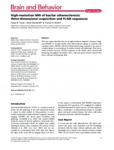
breakdown (see below). Emphasis in this paper is therefore on phenomenological structure formation/dynamics rather than statistics. In the controlled-transition simulation under consideration, first the steady laminar Falkner–Skan-type boundary layer is calculated using 2-D (semi-implicit) DNS. This highly unstable flow close to laminar separation is then disturbed by a 2-D and a symmetrical pair of oblique 3-D waves of equal (fundamental) frequency within a disturbance strip by timewise periodic blowing and suction at the wall. The induced Tollmien–Schlichting waves grow downstream by primary and secondary instability (3-D DNS). Eventually, the disturbance spectrum fills up by nonlinear wave interactions that are enriched by numerial errors (truncation and round-off), giving rise to non-periodic flow behavior. The spatio-temporal formation and evolution of the high-shear layer, situated on top of the 3-vortex with its downstream end being the 3-head, is shown in Figure 8a. Plotted are contour lines of total spanwise vorticity (ωz ) in the peak plane (plane z/λz = 0.5 with the largest disturbance amplitudes during transition) at successive time instances during one fundamental disturbance period T . The plots are stretched in y-direction by a factor of 2.7 for better illustration. The last picture (at tr /T = 5.0, tr = t − tref , tref = 15T ) shows the time instance just prior to the first detachment event at the 3-tip (elliptical vorticity concentration at x = 4.83) from where several CS-Is are shed per period. The insert above displays the corresponding streamwise-velocity (u) contours, where a distinct minimum can be localized below the maximum total vorticity concentration, thus indicating the center of a CS-I (giving the “spike” signal in the velocity traces observed in experiments). In front of the structure (still CS-I and II connected) the first strong increase of the wall shear is visible (cf. Figure 10). In Figure 8b the shear-layer situation at spanwise co-peak position – z/λz = peak ± λz /2, with the second largest disturbance amplitudes – is plotted. The lower structure between 4.6 < x < 4.8, 0 < y < 10 periodically evolves from an upstream situated, relatively strong instantaneous separation zone (see insert) that locally arises due to large disturbance amplitudes in the decelerated base flow (and only therein). This structure is connected with a parallel, rather than converging, streamwise vortex system under
374
M.J. KLOKER
Figure 9. Instantaneous total spanwise-vorticity contours in spanwise peak position (ωz = 0.28–0.64/0.04) near the wall. Close-ups of marked regions in Figure 8a, 5.03 ≤ x ≤ 5.37, 0 ≤ y ≤ 5; tr /T = 4.78–5.0/0.02 from top. Bottom: streamwise-velocity contours (u = −0.125–0.825/0.05) for tr /T = 5.0. For designation of capitals see text.
SPATIAL DIRECT NUMERICAL SIMULATION
375
Figure 10. Instantaneous distribution of local skin-friction coefficient (500cf ) along x at spanwise peak (top) and co-peak position (bottom) for tr /T = 3 - -; 4 – –, 5 —.
Figure 11. Instantaneous streamwise velocity contours in wall-parallel x–z-plane y + = 10 at tr /T = 5.0. Dark regions: u ≈ 0.12; light regions: u ≈ 0.48.
376
M.J. KLOKER
it [5, 6]; it eventually breaks down into many vortex rings (CS-I) downstream (also called “cut and connect event” or Crow instability, see, e.g., [16]). In Figure 9, close-ups of the near-wall regions marked in Figure 8a are presented for tr /T = 4.78 and successive instants with 1(tr /T ) = 1/50 up to tr /T = 5.0; y = 2 in the plots corresponds to y + ≈ 30 in wall units. At x = 5.21, tr /T = 4.78, a local high-shear structure (“A”) comparable to the one discussed with Figure 8a is visible that consecutively undergoes a comparable evolution that can be viewed as a bursting event with ejection (A1, CS-I)) and sweep (A2/A3, A3:CS-II)). The concentration A2 moves to the wall as observed for its large-scale relative in zeropressure-gradient transition [6, 9] (we note that that the imposed pressure gradient is weak for turbulent flow). The time scale is about 1/7 and the spatial scale about 1/8. The evolution of the larger structure B is qualitatively similar but much slower in time. Structures coming from the “inertia” region above can also be observed, viz. C, D. The latter merges with an A-type structure, eventually undergoing the A2/A3 sequence. In any case, CS-Is are clearly identifiable by the u contour lines for tr /T = 5.0, most pronounced near x = 5.34. In Figure 10 the local skin-friction coefficient is plotted versus x at the end of three consecutive disturbance periods in the peak and co-peak plane. In peak, violent randomization sets in after the first strong wall-shear increase at x = 4.83 in connection with the dominant shear-structure in Figure 8a; in co-peak the non-periodicity starts earlier. This confirms that randomization arises due to multiple formation and detachment of CS-Is with multiple reconnection of remaining “legs”, a process being extremely sensitive to (background) disturbances. Finally, Figure 11 illustrates regions of high and low velocity (streaks) in the plane y + = 10. In some regions a spacing of about 1z+ ≈ 100 can be observed (note that the basic spanwise wavelength λ+ z ≈ 973), the value often found in experiments. 4. Outlook Despite the used grid spacings (over-)fulfill the generally agreed limits, we feel that a slight refinement in streamwise direction is still necessary (and possible in our situation) to once fully secure the findings of CS-dynamics. Moreover, the identification of vortical entities by the λ2 -method [17], based on the second eigenvalue of a matrix that is nonlinearly associated with the velocity gradient tensor, can be helpful. In general, the developed DNS code for spatial flow evolution can now be used to attack problems of flow control in end-stage transition and early turbulence as well as stronger pressure gradients, to name but a few. References 1.
Spalart, P.R. and Watmuff, J.H., Experimental and numerical study of a turbulent boundary layer with pressure gradients. J. Fluid Mech. 249 (1993) 337–371.
SPATIAL DIRECT NUMERICAL SIMULATION
2. 3.
4. 5.
6. 7.
8. 9. 10. 11. 12.
13. 14. 15. 16.
17.
377
Lele, S.K., Compact finite difference schemes with spectral-like resolution. J. Comp. Phys. 103 (1992) 16–42. (a) Kloker, M., ODE solvers: Charts of stability regions and solution behavior. (b) Kloker, M., Time-marching FD solvers for the unsteady 1-D advection/diffusion equation with u(x, t) ∼ f (t) exp(ikx): Charts of solution behavior. Institutsberichte, Institut für Aerodynamik und Gasdynamik, Universität Stuttgart (1996). Turkel, E., On the practical use of high-order methods for hyperbolic systems. J. Comp. Phys. 35 (1980) 319–340. Kloker, M. and Fasel, H., Direct numerical simulation of boundary-layer transition with strong adverse pressure gradient. In: Kobayashi, R. (ed.), Laminar-Turbulent Transition. Proc. of 4th IUTAM symposium, Sendai, Japan, 1994. Springer-Verlag, Berlin (1995) pp. 481–488. Kloker, M., Direkte numerische Simulation des laminar-turbulenten Strömungsumschlags in einer stark verzögerten Grenzschicht. Dissertation, Universität Stuttgart (1993). Bestek, H. and Eissler, W., DNS of transition in Mach-4.8 boundary layers at flight conditions. In: Rodi, W. and Bergeles, G. (eds), Engineering Turbulence Modelling and Experiments 3, Proc. 3rd Intern. Symp. on Eng. Turb. Mod. and Measurements, Heraklion-Crete, Greece. Elsevier Science, Amsterda (1996) pp. 611–620. Kloker, M., Konzelmann, U. and Fasel, H. (1993): Outflow boundary conditions for spatial Navier–Stokes simulations of transition boundary layers. AIAA J. 31(4) (1993) 620–628. Rist, U. and Fasel, H., Direct numerical simulation of controlled transition in a flat-plate boundary layer. J. Fluid Mech. 298 (1995) 211–248. Kleiser, L. and Zang, T.A., Numerical simulation of transition in wall-bounded shear flows. Ann. Rev. Fluid Mech. 23 (1991) 495–537. Kim, J.W. and Lee, D.J., Optimized compact finite-difference schemes for solving wave equations. CEAS/AIAA-95-009; 7.1995, (1995) pp. 65–74. Carpenter, M. H., Gottlieb, D. and Abarbanel, S., The stability of numerical boundary treatments for compact high-order finite-difference schemes. ICASE-Report 91-71, Institute for Computer Applications in Science and Engineering, NASA Langley, Hampton, VA, U.S.A. (1991). (a) Kachanov, Y.S., Physical mechanisms of laminar-boundary-layer transition. Ann. Rev. Fluid. Mech. 26 (1994) 411–482. (b) Kachanov, Y.S., Private communication (1997). Robinson, S.K., Coherent motions in the turbulent boundary layer. Ann. Rev. Fluid Mech. 23 (1991) 601–639. Zang, T.A., Numerical simulation of the dynamics of turbulent boundary layers: Perspectives of a transition simulator. Phil. Trans. Roy. Soc. Lond. A 336 (1991) 95–102. Bridges, J., Husain, H. and Hussain, F., Whither coherent structures? Comment 1 on session II. In: Lumley, J.L. (ed.): Whither Turbulence? Turbulence at the Crossroads. Lecture Notes in Physics, Vol. 357. Springer-Verlag, New York (1990) p. 132. Jeong, J. and Hussain, F., On the identification of a vortex. J. Fluid Mech. 285 (1995) 69–94.