A Robust Linear Discrimination Fault Classification Scheme for Three Phase Induction Motors Mohammed Obaid Mustafa
George Nikolakopoulos
Thomas Gustafsson
Lule˚a University of Technology Department of Computer Science, Electrical and Space Engineering Automatic Control Lule˚a, Sweden Email:
[email protected]
Lule˚a University of Technology Department of Computer Science, Electrical and Space Engineering Automatic Control Lule˚a, Sweden Email:
[email protected]
Lule˚a University of Technology Department of Computer Science, Electrical and Space Engineering Automatic Control Lule˚a, Sweden Email:
[email protected]
Abstract—In this article a fault classification algorithm based on a robust linear discrimination scheme, for the case of a squirrel–cage three phase induction motor, will be presented. The suggested scheme is based on a novel feature extraction mechanism from the measured magnitude and phase of current park’s vector pattern. The proposed methodology has the merit to diagnose different types of faults such as: a) broken rotor bar, and b) short circuit in stator winding. The novel feature generation technique is able to transform the problem of fault detection and diagnosis into a simpler space, where direct robust linear discrimination can be applied for solving the classification problem. Robust linear discrimination has been one of the most widely used fault detection method in real life applications, as this methodology seeks for directions that are efficient for discrimination and at the same time requires a straight forward implementation. The efficacy of the proposed scheme will be evaluated based on multiple simulation results for different fault types.
I. I NTRODUCTION In every kind of industrial application, the operation of fault detection and diagnosis for induction motors is of paramount importance. These motors are the most widely utilized electrical machines, mainly due to their advantages such as: stability properties, robustness, durability, power to weight ratio, low production costs and easiness of controlling them [1]. Among the most common faults that can be found in the area of induction motors are: a) opening or shorting of one or more of a stator’s phase winding [2], b) broken rotor bar or cracked rotor’s end-rings [3], c) static or dynamic air–gap irregularities [1], and d) bearing failures [4]. The examined faults may occur during production as small faults or may result from production faults or mechanical, environmental, electromagnetic or thermal pressure on the rotor, when the motor is in operation [5]. Transient events (e.g. during a start up phase of a motor) can accelerate this growth, while all the previous mentioned faulty cases have a direct effect on the produced torque, current and speed of the motor [6]. For all these reasons, an online fault detection and diagnosis scheme [7] is very important for: a) reducing the maintenance cost, b) reducing the risk of unexpected failures, by allowing the early detection of destructive faults, and c) improving the performance of the motors.
Until now, in the related bibliography, many researchers have proposed a variety of techniques for fault detection and diagnosis, in both experimental and simulated verifications. Among those approaches, characteristic examples are methods that utilize: a) the motor current signature analysis [8], b) the electromagnetic torque measurements [9], c) set membership identification [10], [11], d) negative sequence components [12], e) support vector machine [13], f) principal component analysis [14], g) linear discriminant analysis, and h) independent component analysis [15]. In the specific area of model free fault detection and diagnosis, the Linear Discriminant Analysis (LDA) has been applied for fault diagnosis in induction motors [16]. This method is able to separate the feature classes in a low dimensional subspace, even under significant variations. Moreover, Singular Value Decomposition [17] has been utilized in the same problem, especially when direct separation of two data sets cannot be accomplished, and an affine function is needed to approximately classify the data. In general this approach is difficult and rather complicated to be directly applied to real life applications, while the general aim is to reduce the input dimension of the current value vector, measured at each period, by extracting specific feature vectors and in the sequel trying to apply the LDA principle [18], [19]. The novelty and the main contribution of the presented research work, stems from proposing a novel method for extracting features, only based on current measurements and in the sequel applying Robust Linear Discrimination for fault detection and classification. The proposed methodology: a) plots the q − d measured Ids and Iqs stator currents, and b) applies periodic sampling on the resulting state diagram, while features are being extracted based on the magnitude and phase of current park’s vector pattern. The proposed method is suitable for an online implementation, while retains complexity in significant low levels. The output, denoted as the maximum discrimination interval, is being calculated based on the theory of convex optimization and has the merit to include all the possible discrimination faulty lines, calculated by relevant methodologies [20]. This article is structured as it follows. In Section II the
linear discrimination algorithm is being presented, followed by the analysis of the proposed feature extraction mechanism in Section III. In Section IV multiple case studies of different fault types occurrences are being presented that prove the efficiency of the proposed algorithm. Finally, in Section V the conclusions are being drawn. II. ROBUST L INEAR D ISCRIMINATION In most of the cases in pattern recognition and classification problems, two sets of data points C1 , C2 in ℜn are being provided, denoted as C1 : {x1 , . . . , xN }, C2 : {y1 , . . . , yM } and with N, M ∈ Z+ , while the overall goal is to find a f : ℜn → ℜ, which is positive on the first set and negative on the second [20], or: f (xi ) > f (yi )
0, aT yi − b < 0,
i = 1, . . . , N i = 1, . . . , M
(2) Fig. 1.
From an equivalent geometrical point of view, the solution to the previous problem in Eq. (2) can be considered as the problem of finding a hyperplane, which separates these two sets of data points. Since the strict inequalities in Eq. (2) are homogeneous in the terms a and b, a feasible solution exists if and only if the set of the following non strict linear inequalities: aT xi − b ≥
1,
i = 1, . . . , N
a yi − b ≤ −1,
i = 1, . . . , M
T
(3)
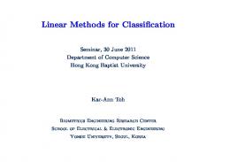
are feasible in the normalized variables of a and b. In Figure 1 a simple example of two data points sets are being depicted, with a linear discriminating function straight line, where the points x1 , . . . , xN and y1 , . . . , yM are represented by open and solid circles notations respectively. In case that the C1 , C2 sets can be linearly discriminated, there is always a polyhedron, which contains affine functions that discriminate the same problem, while these functions can present some robustness to the discrimination problem. In this case, the affine function is being calculated as the function that provides the maximum possible polyhedron width H ∈ ℜ+ , between the positive values at the points xi and the negative values at the points yi . The problem can be solved by convex optimization with the following formulation Maximize Sub ject to
(4)
d aT xi − b ≥ 1, aT yi − b ≤ −1,
k a k2
≤ 1
i = 1, . . . , N i = 1, . . . , M
Data Classification by the utilization of Linear Discrimination
with variables a, b and d. The optimal value d ∗ for this convex problem (with linear objective, linear inequalities, and one quadratic inequality) is positive if and only if the two sets of points can be linearly discriminated. In this case the inequality k a k2 ≤ 1 is always tight at the optimum. From a geometrically, point of view, the solution to this problem is equivalent of finding the thickest hyperplane that separates the two sets of points, while a graphical solution to this linear discrimination problem in Eq. (4) is being depicted in Figure 2. In this figure the optimal calculated width H = 2d is displayed, which is denoted as double of the distance between the convex hulls of the two sets of data points, a property that has been directly derived from the duality of the robust linear discrimination problem described in Eq. (1), while the mathematical solution to the described problem can be straight forward implemented by the utilization of the CVX, a software package for specifying and solving convex programs [21]. In the following Section, the application of the robust linear discrimination technique, combined with the novel suggested feature generation technique will be presented. III. DATA G ENERATION This section will provide an overview of the utilized models for simulating the healthy and the faulty cases of the induction machine. The interested readers are suggested to refer to the articles refereed herein for an extended analysis of the presented modeling approaches.
with A∗b
=
−Lr rs 1 0 L r m rq δ 0
0 −Lr rs 0 Lm rrd
B∗b
=
Lm r s 0 −Ls rrq −wr δ
0
Lm r s wr δ −Ls rrd
B
C. Stator Winding Short Circuit Modeling
Fig. 2. Data Classification by the utilization of Robust Linear Discrimination
A. Model of Three Phase Induction Motor For simulating the healthy case of the induction motor, the following state space equations will be utilized [22], [10], [11], [23]:
diqs dt dids dt diqr dt didr dt
Vqs iqs Vds ids = A i + B 0 qr 0 idr
where: A
=
B
=
−Lr rs 0 Lm r s 1 0 −Lr rs 0 L r 0 −Ls rr m r δ 0 Lm rr −wr δ Lr 0 −Lm 0 1 0 Lr 0 −Lm −L 0 Ls 0 m δ 0 −Lm 0 Ls
0
Lm r s wr δ −Ls rr
and δ = Ls Lr − Lm2 . B. Broken Bar Model of Three Phase Induction Motor The most important factors for the existence of broken bar faults are mainly the thermal, magnetic, residual, dynamic, and mechanical stresses [2]. The event of a broken rotor bar causes asymmetry in the resistance and inductance of the rotor’s phases, which results in asymmetry of the rotating electromagnetic field in the air gap between stator and rotor. Consequently, this will induce frequency harmonics in the stator current. The impact of broken rotor bars can be modeled by unbalancing the rotor resistance, while the inductance changes are being neglected due to their insignificance influence compared to the resistance changes [24], [25]. The stator resistances and inductances stay unchanged [25] and for simplicity purposes, for a squirrel–cage rotor, the end– ring contribution is being also neglected. The modified and the details about the model of induction motor in the case of broken rotor bar could be found it in ([10], [23]). The state space matrices in the faulty case will become A∗b , B∗b and are defined as: A∗b
= −R∗br L−1
In the examined case all the stator parameters are considered to be identical when short circuit happens in the winding of the three phase induction motor, while both stator’s resistance and inductance, as also the mutual inductances between stator and rotor will be directly affected. In the case of such a fault, the corresponding modified (faulty) state space motor realization should be utilized. In this case the q − d reference frame transformation needs to be performed to these equations and by assuming that the short circuit occurs only in phase a of the stator for simplification reasons and without loosing generality, the resistance and inductance matrix of stator are being defined with shorted turns in the q − d reference frame as [25]: rs11 0 rs13 qd0 0 (5) rsf = rs 0 rs22 rs31 0 rs33 where rqd0 sf is the stator winding resistance matrix in the faulty case. Let gsa be the percentage of the remaining un–shorted stator windings in stator phase a and the non–zero elements of the matrix rqd0 sf are being defined as [25]: 2 1 (2gas + 1) , rs13 = (gas − 1) , rs22 = 1 3 3 1 1 rs31 = (gas − 1) , rs33 = (gas + 1) (6) 3 3 The modified and the details about the model of induction motor in the case of short circuit could be found it in [10], [11]). Therefore the matrices A and B in the faulty case will change and become as: rs11
=
A∗ss B∗ss
= −R∗f L∗f −1 =
L∗f −1
(7) (8)
D. Data Feature Extraction In all the model free fault detection and diagnosis methodologies, the feature extraction is one of the most significant step. The overall aim is to create a new simplified data set, from raw measurements, achieving a better minimization of the misclassification rate, denoted as the total number of incorrect classifications, divided by the total number of classifications. This dimensionality reduction of the feature extraction step is important for increasing the successful classification, especially during the evaluation of the suggested scheme with data that do not belong to the initially utilized training sets. In the existing literature, as it has been mentioned in the introduction, various feature extraction techniques have been already described. The main novelty of this article, stems
from the utilization of a new feature extraction technique that could lead in a straight forward linear classification problem, where light computational methods, like the Robust Linear Discrimination technique could be directly applied. For generating the necessary data sets for the application of the suggested discrimination based fault detection, simulated models of a three phase induction motor, under the healthy and faulty cases (broken rotor bar and short circuit in stator winding), in the q − d framework, have been adopted as it has been previously presented. In this simulation framework, which is being depicted in Figure 3, the measured (noise corrupted) motor currents (Iqs , Ids ) are been fed to the proposed feature extraction mechanism and in the sequel to the fault diagnosis algorithm. Fig. 4.
Fig. 3.
Current Park’s vector pattern for feature extraction
Proposed Modular Scheme for Fault classification
The feature generation mechanism is based initially on the sampled three phase motor currents Ia , Ib , Ic . In the sequel these currents are being transformed to the Parks vector components Iqs and Ids , by the utilization of the following transformations [26]: r r r 2 1 1 Ia − Ib − Ic Ids = 3 6 6 r r 1 1 Iqs = Ib − Ic (9) 2 2 The three phase currents lead to a Park’s vector with the following components [26]: √ 6 I sin ω t Ids = 2 √ 6 π I sin(ω t − ) (10) Iqs = 2 2 where I, Ia , Ib and Ic are the maximum value of the supply phase currents, and ω is the supply frequency. By plotting the current Park’s vector pattern, (Iqs versus Ids ), this relationship takes a form of multiple overlapping circular pattern, centered at the origin of the coordinates as illustrated in Figure 4. The last step, in the proposed methodology for feature extraction, is the circular sampling of circular shape and representing every point of the Iqs − Ids phase by its distance to the center of the circular Di ∈ ℜ+ and the angle θi ∈ [0, 2π ] from the horizontal axis Ids , with: q Di = I2ds (i) + I2qs (i) (11) The resulting data set, which contains multiple measure-
Fig. 5.
Proposed Flowchart
ments of distances Di and angles θi , is being utilized as the new feature database in the last step of the robust fault discrimination. The proposed overall algorithm is also presented in the flowchart in Figure 5 and as it will be demonstrated in the following section, the proposed feature extraction has the significant benefit of simplicity and fast real time application, for all the examined faulty cases. IV. S IMULATION R ESULTS The proposed scheme for fault detection and diagnosis is being evaluated on a model of three phase induction motor having the parameters depicted in Table 1. The cases that will be examined in the sequel are: a) 1 broken rotor Bar, b) 2% short circuit, while all the simulation results are being carried with respect to the presented induction motor types in Section 2.
TABLE I I NDUCTION M OTOR S IMULATED PARAMETERS
1.205 Normal case Broken bar case
Pole Numbers
4
rs
0.0616 per unit
Input Voltage
240V
rr
0.0753 per unit
Frequency
50Hz
J
0.00155 Kg.m
0.019 per unit
Ls
0.019 per unit
Lm
0.01833 per unit
Nb
28
1.195
1.19
D
i
Lr
1.2
1.185
H=0.0068
1.18
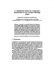
A. Cases Study ‘Broken 1 rotor Bar Fault’ In this case, the proposed methodology is being evaluated in fault diagnosis between an one broken rotor bar fault and the healthy case. Figure 6 depicts the Park’s vector pattern of the Ids and Iqs currents, both in the case of the healthy and the broken bar case, while Figure 7 presents the extracted features based on the distances Di calculated at different θi . The obtained data sets, due to the proposed feature extraction, can be easily separated by the utilization of the robust linear discrimination algorithm, and thus a clear classification of the healthy and the faulty case can be robustly performed, by having a hyperplane of a H=0.068 width. For the presented results the parameters of the affine function have been calculated as: a = [0, −1], b = −1.178. 1.5 Broken Bar case Normal case
1
1.175
1.17
1.165 0
5
10
15
20
25
30
35
θ
i
Fig. 7. Robust linear discrimination between healthy and broken 1 rotor bar case
data sets for Di and θi are presented in Figure 9. As previously, the proposed feature extraction algorithm has the merit to produce easily separated data sets, where the robust linear discrimination algorithm can be directly applied, without the need of data pre-processing. For the examined test case, the discriminating hyperplane, between the normal case and the short circuit case, had a width H = 0.012, while the parameters of the affine function have been calculated as: a = [0, −1], b = −1.189. 1.5
0.5
Short circuit case Normal case
Iqs
1 0
0.5
I
qs
−0.5
−1
0
−0.5 −1.5 −1.5
−1
−0.5
0
0.5
1
1.5
Ids −1
Fig. 6. Park’s vector pattern of stator currents for a motor with broken 1 rotor bar and healthy case −1.5 −1.5
B. Cases Study ‘2% Short Circuit’ In the second simulated case study the fault diagnosis between 2% short circuit in stator winding fault and the healthy case has been considered. In Figure 8 the corresponding Park’s vector pattern is being depicted, for both the examined test cases, where as it can be observed the relation between Iqs and Ids and the gab between the two circular has been bigger, when compared with the first examined case. The resulting
−1
−0.5
0
0.5
1
1.5
Ids
Fig. 8. Park’s vector pattern of stator currents for a motor with short circuit case and healthy case
V. C ONCLUSIONS In this article a fault diagnosis method for the case of squirrel–cage Three Phase Induction Motors based on robust
1.21 Normal case Short circuit case 1.205
1.2
1.195
Di
1.19
1.185
H=0.012 1.18
1.175
1.17
1.165 0
5
10
15
20
25
30
35
θi
Fig. 9. case
Robust linear discrimination between healthy and %1 short circuit
linear discrimination has been presented. The suggested scheme has the capability to diagnose different types of faults: a) normal case b) broken rotor bar and c) short circuit in stator winding based on the proposed on–line fault condition monitoring scheme. The efficacy of the proposed scheme has been evaluated based on multiple simulation results for different fault types.
R EFERENCES [1] G. G. Acosta, C. J. Verucchi, and E. R. Gelso, “A current monitoring system for diagnosing electrical failures in induction motors,” Mechanical Systems and Signal Processing, vol. 20, no. 4, pp. 953–965, Oct 2004. [2] S. Nandi and H. Toliyat, “Condition monitoring and fault diagnosis of electrical machines-a review,” IEEE Transactions on Energy Conversion, vol. 20, no. 4, pp. 719–729, Dec. 2005. [3] P. Santos and T. Lubiny, “A simplified induction machine model to study rotor broken bar effects and fault detection,” European Transactions on Electrical Power, vol. 20, p. 611, 2010. [4] I. Y. Anel, I. Azenol, and M. E. H. Benbouzid, “Induction Motors Bearing Failures Detection and Diagnosis Using a RBF ANN Park Pattern Based Method,” International Electric Machines and Drives Conference, pp. 1073–1078, Mayl 2007. [5] A. H. Bonnett and G. C. Houkup, “Analysis of stator and rotor faults in three-phase squirrel-cage induction motors,” IEEE Transactions on Industry Applications 28, No. 4, pp. 921937, Aug., pp. 921–937, Aug. 1992. [6] J. Penman and A. Stavrou, “Broken rotor bars their effect on the transient performance of induction machines,” IEE Proc.-Electrical Power Application., vol. 143, no. 6, pp. 449–457, NOv. 1996. [7] K. S. Bharathi, M. Shajeev, R. N. Pravin, P. K. Prasath, and C. K. Santhosh, “Application of multi-wavelet denoising and support vector classifier in induction motor fault conditioning,” Proceedings published by International Journal of Computer Applications (IJCA), pp. 1–6, October 2011. [8] W. T. Thomson and M. Fenger, “Current signature analysis to detect induction motor faults,” IEEE Transactions on Industry Applications, vol. 7, no. 6, pp. 26–34, Jul.-Aug. 2001. [9] A. J. F. Thollon and G. Grellet, “Asynchronous motor cage fault detection through electromagnetic torque measurement,” European Transactions on Electrical Power, vol. 3, no. 5, pp. 375–378, Sept.-Oct. 1993.
[10] M. O. Mustafa, G. Nikolakopoulos, and T. Guastafsson, “A fault diagnosis scheme for three phase induction motors based on uncertainty bounds,” Proceedings of the 38th Annual Conference of the IEEE Industrial Electronics Society, IECON2012, October 2012. [11] ——, “Stator winding short circuit fault detection based on set membership identification for three phase induction motors,” Proceedings of IEEE, 20th Mediterranean Conference on Control and Automation, MED12, pp. 290–296, July 2012. [12] G. B. Kliman, W. J. Premerlani, R. A. Koegl, and D. Hoeweler, “A new approach to on-line turn fault detection in AC motors,” Thirty-First IAS Annual Meeting in Proceedings of the IEEE Industry Applications Conference, vol. 1, pp. 687–693, 1996. [13] D. Matic, F. Kulic, M. P. Sanchez, and I. Kamenko, “Support vector machine classifier for diagnosis in electrical machines: Application to broken bar,” Expert Systems with Applications, vol. 39, pp. 8681–8689, 2012. [14] J. R. Y. Tharrault, G. Mourot and D.Maquin, “Fault detection and isolation with robust principal component analysis,” International Journal of Applied Mathematics and Computer Science, vol. 18, no. 4, p. 429442, 2008. [15] A. Widodo, B. S. Yang, and T. Han, “Combination of independent component analysis and support vector machines for intelligent faults diagnosis of induction motors,” Expert Systems with Applications, vol. 32, pp. 299–312, 2007. [16] A. da Silva Soares and R. K. H. Galvo, “Fault detection using linear discriminant analysis with selection of process variables and time lags,” IEEE International Conference on Industrial Technology (ICIT), 2010, pp. 217 – 222, March 2010. [17] B. Y. A. Widodo and T. Han, “Combination of independent component analysis and support vector machines for intelligent faults diagnosis of induction motors,” ELSEVIER, Expert Systems with Applications, vol. 32, no. 2, pp. 299–312, February 2007. [18] D. J. Lee, J. H. Park, D. H. Kim, and M. G. Chun, “Fault diagnosis of induction motor using linear discriminant analysis,” KnowledgeBased Intelligent Information and Engineering Systems Lecture Notes in Computer Science, vol. 3684, pp. 860– 865, 2005. [19] D. Y. Jung, S. M. Lee, H. M. Wang, J. H. Kim, and S. H. Lee, “Fault detection method with PCA and LDA and its application to induction motor ,” Journal of Central South University of Technology, vol. 17, pp. 1238–1242, December 2010. [20] S. Boyd and L. Vandenberghe, Convex Optimization, N. Y. Cambridge University Press, Ed., 2009. [21] I. CVX Research, “CVX: Matlab software for disciplined convex programming, version 2.0 beta,” http://cvxr.com/cvx, Sep. 2012. [22] P. Vas, Electrical Machines and Drives, O. S. Publication, Ed., 1992. [23] M. O. Mustafa, G. Nikolakopoulos, T. Guastafsson, and B. M. Saied, “Broken bar fault detection based on set membership identification for three phase induction motors,” Proceedings of the 9th International Conference on Informatics in Control, Automation and Robotics, ICINCO 2012, pp. 224–231, July 2012. [24] A. Bellini, F. Filippetti, G. Franceschini, C. Tassoni, and G. Kliman, “Quantitative evaluation of induction motor broken bars by means of electrical signature analysis,” IEEE Transactions on Industry Application, vol. 37, no. 5, pp. 1248–1255, Sept/Oct 2001. [25] S. Chen and R. Zivanovic, “Modelling and simulation of stator and rotor fault conditions in induction machines for testing fault diagnostic techniques,” European Transactions On Electrical Power, vol. 20, pp. 611–629, April 2009. [26] H. Nejjari and M. E. Benbouzid, “Monitoring and diagnosis of induction motors electrical faults using a current parks vector pattern learning approach,” IEEE Transactions on Industry Applications, vol. 36, no. 3, pp. 730–735, 2000.