The International Archives of the Photogrammetry, Remote Sensing and Spatial Information Sciences, Volume XLI-B1, 2016 XXIII ISPRS Congress, 12–19 July 2016, Prague, Czech Republic
A ROBUST REGISTRATION ALGORITHM FOR POINT CLOUDS FROM UAV IMAGES FOR CHANGE DETECTION A. Al-Rawabdeh a*, H. Al-Gurrani a, K. Al-Durgham a, I. Detchev a, F. He b, N. El-Sheimy a, and A. Habib b a
Dep’t of Geomatics Engineering, University of Calgary, 2500 University Dr. NW, Calgary, AB, Canada T2N 1N4 - (amalrawa, htattya, kmaldurg, i.detchev, elsheimy)@ucalgary.ca b Lyles School of Civil Engineering, Purdue University, 47907 West Lafayette, IN, USA -
[email protected] Commission I/Vb, ICWG I/Vb
KEY WORDS: landslide dynamics, normal distance, bundle block adjustment with self-calibration, structure from motion, 3D dense surface reconstruction, Unmanned Aerial Vehicle (UAV) ABSTRACT: Landslides are among the major threats to urban landscape and manmade infrastructure. They often cause economic losses, property damages, and loss of lives. Temporal monitoring data of landslides from different epochs empowers the evaluation of landslide progression. Alignment of overlapping surfaces from two or more epochs is crucial for the proper analysis of landslide dynamics. The traditional methods for point-cloud-based landslide monitoring rely on using a variation of the Iterative Closest Point (ICP) registration procedure to align any reconstructed surfaces from different epochs to a common reference frame. However, sometimes the ICP-based registration can fail or may not provide sufficient accuracy. For example, point clouds from different epochs might fit to local minima due to lack of geometrical variability within the data. Also, manual interaction is required to exclude any non-stable areas from the registration process. In this paper, a robust image-based registration method is introduced for the simultaneous evaluation of all registration parameters. This includes the Interior Orientation Parameters (IOPs) of the camera and the Exterior Orientation Parameters (EOPs) of the involved images from all available observation epochs via a bundle block adjustment with selfcalibration. Next, a semi-global dense matching technique is implemented to generate dense 3D point clouds for each epoch using the images captured in a particular epoch separately. The normal distances between any two consecutive point clouds can then be readily computed, because the point clouds are already effectively co-registered. A low-cost DJI Phantom II Unmanned Aerial Vehicle (UAV) was customised and used in this research for temporal data collection over an active soil creep area in Lethbridge, Alberta, Canada. The customisation included adding a GPS logger and a Large-Field-Of-View (LFOV) action camera which facilitated capturing high-resolution geo-tagged images in two epochs over the period of one year (i.e., May 2014 and May 2015). Note that due to the coarse accuracy of the on-board GPS receiver (e.g., +/- 5-10 m) the geo-tagged positions of the images were only used as initial values in the bundle block adjustment. Normal distances, signifying detected changes, varying from 20 cm to 4 m were identified between the two epochs. The accuracy of the co-registered surfaces was estimated by comparing non-active patches within the monitored area of interest. Since these non-active sub-areas are stationary, the computed normal distances should theoretically be close to zero. The quality control of the registration results showed that the average normal distance was approximately 4 cm, which is within the noise level of the reconstructed surfaces.
1. INTRODUCTION Change detection is the process of identifying differences and/or geometrical changes in the state of an object or a phenomenon over a specified period of time (Singh, 1989). Changes and displacements are fundamental indications of the Earth surface’s mass movements, such as landslides, soil creep, and rock slides that are caused by either human activity or natural processes. An automatic detection of the Earth’s surface change is a useful tool for topographic map makers and is important for providing timely, reliable, and appropriate decision-making information in emergency situations. Change detection is useful for a variety of applications, ranging from large scale investigations, such as land-use change analyses, disaster monitoring, and environmental modeling, to small scale investigations (Murakami et al., 1999; Walter, 2004; Vögtle and Steinle, 2004). This would include the damage assessments of building infrastructures, stress detection in engineering structures, and the deformation of small objects (Tsakiri and Anagnostopoulos, 2015). The monitoring of landslides requires on-going assessments of the extent and the rate of horizontal and vertical displacements of the surface’s terrain. It further necessitates accurate and high-resolution representations of the Earth’s surface.
Change detection is commonly performed via ground-based methods of landslide monitoring and can be costly, time consuming, and limited in their spatial and temporal coverage. Therefore, the processing steps of a change detection analysis should aim to be as automated as possible, and thereby, minimize the manual work involved, saving time and money. Change detection can also be performed via an image analysis using object-to-background separation or a simple subtraction technique between the images. This process, though, is plagued by misinformation that is caused by shadows or other local illumination problems (Kang and Lu 2011). A relatively recent development, a new remote sensing technology, Unmanned Aerial Vehicle (UAVs), have a strong potential to provide access to easy information regarding landslide-prone areas. Temporal monitoring data of landslides using UAV images taken at different times greatly facilitates the evaluation of landslide progression. Often used as a supplement to field surveys, and as an alternative to airborne and terrestrial LiDAR, this technology is steadily decreasing in cost due to the proliferation of inexpensive cameras, and the diversity of aerial platforms. Furthermore, the use of UAVs avoids the inherent limitations associated with using terrestrial LiDAR. But because UAV technology itself is nascent, automatic change detection involving low-altitude UAV image-based point clouds, though
This contribution has been peer-reviewed. doi:10.5194/isprsarchives-XLI-B1-765-2016
765
The International Archives of the Photogrammetry, Remote Sensing and Spatial Information Sciences, Volume XLI-B1, 2016 XXIII ISPRS Congress, 12–19 July 2016, Prague, Czech Republic
proven, is relatively unexplored and little research has been done in terms of accounting for changes in vertical displacement. To detect changes in an area of interest over two or more different epochs, the alignment of the overlapping surfaces from the point clouds is crucial for analysing the landslide’s dynamics. It is important to remember that a comparison can only be obtained by aligning different point cloud models into the same coordinate system. Errors in the registration process propagate into the final point cloud and they influence the ability to detect the changes. It is for this reason that the accurate registration of 3D point clouds is an increasingly topical area of research. Registration approaches that can be found within the literature can be categorized into either coarse registration or fine registration algorithms (Matabosch et al., 2005). Coarse registration algorithms are used in order to establish the rough alignment between involved point cloud models. This type of registration algorithm does not require approximate values for those transformational parameters that are of a good quality. On the other hand, fine registration algorithms are usually employed in order to achieve a precise alignment between the involved point cloud models, by starting from good approximations of the transformational parameters. The objective of this paper is to develop a robust, rapid and low-cost set of automatic techniques to detect, with a high degree of precision, changes within a multi-temporal, dense 3D UAV image-based point cloud. This is paramount in order to evaluate the effectiveness of change detection for identifying and quantifying movement in areas of erosion and deposition caused by rain events and human activities, as well as regularly updating topographic data in landslide areas prone to rapid change. Therefore, a key step in the processing chain is the ability to distinguish changing surfaces from unchanging surfaces using two-image-set acquisitions with different time stamps. Currently, generated dense 3D point clouds require additional processing steps to arrive at a change detection analysis, including the registration process, where all point clouds are transformed to the same coordinate system. This registration process is a conformal transformation, such that with each point cloud, seven transformation parameters are defined: a 3D translation and a 3D rotation, containing three parameters each, and a scaling factor - often assumed to be different for each point cloud generated using the aforementioned technique.
and Böhm, 2005); and (4) surface/point cloud matching techniques using all available point clouds (i.e., the Iterative Closest Point (ICP) method and its variants) (Besl and McKay,1992; Al-Manasir and Fraser, 2006; Chen and Medioni, 1991; Salvi et al., 2007; Bae and Lichti, 2008; Schürch et al., 2011; Habib et al., 2010; Al-Durgham and Habib, 2013; Gruen and Akca, 2005). Each of these various alternatives possesses their own advantages and disadvantages. 2.1 Target-based Methods A target-based registration uses signalized targets in order to obtain exact point correspondences between two or more point clouds for a coarse registration (Lichti and Skaloud, 2010; Liang et al., 2014). Targets are objects that are placed within the scanner’s field of view and are not moved throughout any of the scanning positions. Some of the disadvantages that are associated with these methods are: 1) it requires additional and sometimes cumbersome equipment; 2) extra time for setting up the targets in stable areas; 3) targets that are not always visible in successive scans and that require strategic placement for the registration. The precision surveillance of targets is necessary by a second instrument for the geo-referencing. The instruments used for geo-referencing primarily include Differential Global Positioning Systems (DGPS) and/or total stations (Schürch et al., 2011; Montreuil et al., 2013). It is important to note that a human effort is required for placing the targets within the area of interest. This can be a restricted procedure and potentially difficult, because of the limited access to an unstable survey area (i.e., the landslide area). In addition, the initial alignment (coarse alignment) between the involved point cloud models is manually achieved by visualizing the point clouds by using specially-developed software (i.e., in order to determine the initial approximations of the transformational parameters). However, the identification of a specific point in the point cloud models, even from the TLS, or an image-based point cloud, is hard and unreliable, since the surface model’s footprints are irregularly-distributed (Habib et al., 2008). Furthermore, a drawback of the TLS system is that it is not exactly known which point on an object causes the reflection. With the diverging laser beam, the area of the footprint increases with the range. At larger distances, it is difficult to exactly identify a point in the point cloud as a tie point. And so, a registration that is based on clearly identifiable points will introduce an error in the point clouds. Thereafter, a fine registration is required through point-based registration algorithms. 2.2 Feature-based Registration
2. BACKGROUND In order to estimate change on the Earth’s surface, it is important to remember that a comparison can only be obtained by aligning different point cloud models into a common coordinate system. A basic technique for the 3D registration method is to determine the conformal transformation parameters (three shifts, three rotations, and a scale factor) between two or more overlapping point clouds. For a well-calibrated laser scanner, the scale factor is considered to be unity, since the laser ranging principle provides a true scale. This is not the case with image-based point clouds due to them being generated with an arbitrary coordinate system and scale.
Feature-based registration methods use simple geometric shapes (such as lines, planes, cylinders, and spheres) in order to establish the coarse alignment between two or more point cloud models. This type of a method is effective for registering the point clouds of industrial facilities where many objects with a regular geometric shape exist (Liang, et al., 2014). They are, however, not used for change detection applications. For additional details, the reader is directed to examine the following literature: Kang et al. (2009); Rabbani et al. (2007); Jaw and Chaung (2008); Al Durgham and Habib (2014); Kwak et al. (2006); Gielsdorf et al. (2008). 2.3 Direct Geo-referencing Based on GPS/INS
The registration approaches found within the literature can be categorized into the following: (1) target-based methods; (2) feature-based methods; (3) direct geo-referencing methods that are based on GNSS/INS (El-Sheimy, 2005; Habib et al., 2010; Wikinson and Mohamed, 2010; Wen et al., 2014; Schuhmacher
Direct geo-referencing methods are applicable for airborne laser scanners (Habib et al., 2010), mobile terrestrial laser scanners (Wen et al., 2014), and static terrestrial laser scanners (Wikinson and Mohamed, 2010; Reshetyuk, 2010). In direct
This contribution has been peer-reviewed. doi:10.5194/isprsarchives-XLI-B1-765-2016
766
The International Archives of the Photogrammetry, Remote Sensing and Spatial Information Sciences, Volume XLI-B1, 2016 XXIII ISPRS Congress, 12–19 July 2016, Prague, Czech Republic
geo-referencing methods, additional sensors, such as the GNSS and the INS integration systems, are combined with a utilized sensor (i.e., laser scanners and/or digital cameras). Integrated GNSS/INS units are used in order to define the absolute position and the orientation of the utilized sensor relative to a mapping frame. This establishes the alignment between the overlapping point clouds. The main advantage of direct georeferencing units is that they reduce or even eliminate the requirement for ground control points. This is beneficial when mapping inaccessible areas, as well as reducing the overall cost of the mapping procedures (Lari et al., 2015). However, direct geo-referencing is not preferable for most static terrestrial laser scanning and low-cost UAV system applications, due to the fact that the incorporation of the direct geo-referencing sensors imposes additional expenses on the scanning system. The quality of the alignment is also dependent on the accuracy of the utilized GNSS/INS units. In the case of a less accurate GNSS/INS-based position and less precise orientation information, a point-based registration is applied as a further step in order to achieve the fine alignment between the point clouds. 2.4 Point Cloud Matching Techniques The ICP method is commonly used for the registration of a point cloud and has many variations. Its primary disadvantage is the need for overlapping areas with diverse geometry between data sets and a reasonable initial estimation of transformation parameters. Without quality initial parameters and large overlapping data sets, the ICP method, and its variants, can fail to estimate reliable registration parameters. It is also a slow algorithm requiring the use of all available points in the datasets. An inherent vulnerability in the abovementioned ICP algorithm is its reliance on an interactive approach, requiring users to guide the initial coarse alignment process by manually providing correspondences before running the final fine registration (Tombari and Remondion, 2013). Turner et al., (2015) used commercial software (i.e., Cloud Compare) in order to register each pair of point clouds that were collected from the western slopes of the Huon Valley in southern Tasmania, 35 km southwest of the capital city of Hobart. This method was applied after removing the active landslide areas, so that only points in the surrounding nonactive areas were considered. In order for them to run in the CloudCompare software and for the surrounding non-active areas be estimated, an ICP algorithm was used on each pair of the point clouds and transformational parameters, including rotational, translational, and scale. They found that the translational parameters had shifts of 20 cm to 30 cm in one or more of the three axes. Theoretically, this was due to the ICP converging on a local minimum in which a large translation minimized the error. Immerzeel et al., (2014) deployed a UAV over a debris-covered Himalayan glacier in Nepal. Based on stereo imaging from two campaigns in May and October 2013 and by using the SfM algorithm, they derived highly-detailed ortho-mosaics and DEMs. They used the differential GPS observations collected in the field in order to geometrically correct the orthophoto. Founded on DEM differencing and manual feature tracking, they derived the mass loss and the surface velocity of the glacier with a high spatial accuracy. Wang et al., (2014) reconstructed the 3D surface of a detritus area located at the Zijin Mine in the Fujian Province, China. They implemented different algorithms, such as the SfM system
and the Patch-Based Multiview Stereo (PMVS) system, to generate a dense 3D point cloud from the UAV images. In this case study, they used 17 GCPs for geo-referencing a 3D reconstruction point cloud, with respect to the geographic coordinate system, because the reconstructed point cloud when using SfM was defined in an arbitrary coordinate system. The accuracy of the 3D geometry was evaluated by using both the GCPs and the TLS point cloud. The UAV point cloud accuracy was first evaluated at a point level, by comparing the absolute coordinates between the UAV point cloud and the GCPs. Further analyses were derived based upon the difference between the DSM generated from the UAV image-based point cloud and the TLS. Lucieer et al., (2014) used a UAV platform equipped with a standard digital camera and GPS in order to collect multitemporal sets of extremely high-resolution RGB images over the active Home Hill landslide in Tasmania. Multi-View Stereopsis (MVS) and SfM methods were used to convert the overlapping images into 3D point clouds, DEMs, and orthomosaics. The horizontal landslide displacements were detected by using a semi-automatic image correlation technique (COSICorr algorithm) after converting the two DEMs from different epochs into shaded relief images. The algorithm successfully quantified the movements of the large pieces of ground material, but was less successful when mapping the main landslide scarp. Wujanz (2012) analysed the significance / informative value of quality measures in surface-based registration processes by using dataset effects of deformation onto commercial (GFaI Final Surface 3.0.5, Leica Cyclone 7.1, and Raindrop Geomatics Studio 12 software) and scientific (4-Points Congruent Sets Algorithm) applications. The dataset representing the “snow” dataset was captured using TLS of a roof section over two different time periods. A snow mantle of roughly 16 cm can be found on the roof in the first dataset while most of the snow had melted when the second point cloud was captured. In order to compute the transformation parameters between these datasets all “deformed” areas covered by snow were removed (only for the reference dataset) before the registration process began. The results indicated that none of the implemented quality measures led to a definitive conclusion that the “best” result had been achieved.
3. PROPOSED METHODOLOGY The methodology used to detect changes between two UAV image-based point clouds, collected at different times, consists of five steps: 1. Data acquisition of two or more epochs; 2. Structure from motion (SfM); 3. Bundle block adjustment with self-calibration; 4. Semi-global dense matching; 5. Estimation of normal distances between point clouds derived in consecutive epochs. The first step includes the customization of the equipment by adding a GPS logger and a large-field-of-view (LFOV) action camera facilitating the capture of high-resolution, geo-tagged images (see Figure 1a). Due to the course accuracy of the onboard GPS receiver (e.g., ± 5-10 m) geo-tagged positions of the images are only used as initial values for the procedures to follow. The second step is a SfM procedure, where preliminary image exterior orientation parameters (EOPs), camera IOPs, and ground coordinates of tie points are estimated using the images
This contribution has been peer-reviewed. doi:10.5194/isprsarchives-XLI-B1-765-2016
767
The International Archives of the Photogrammetry, Remote Sensing and Spatial Information Sciences, Volume XLI-B1, 2016 XXIII ISPRS Congress, 12–19 July 2016, Prague, Czech Republic
from all observed epochs. Note that conjugate points are collected and matched via the Scale-Invariant Feature Transform (SIFT) detector and descriptor. In the third step, the parameters estimated in the SfM procedure are refined through a global photogrammetric bundle block adjustment with selfcalibration. The fourth step is a semi-global dense matching procedure. It is implemented to generate a dense 3D point cloud for each observed epoch using the images captured only at that particular epoch. Note that thanks to the bundle adjustment procedure the separate point clouds are now effectively coregistered to a common reference frame. Finally, the fifth step is the computation of normal distances between any two consecutive point clouds.
and autonomously fly the UAV through a series of predefined, 16 3D GPS waypoints.
3.1 UAV System and Camera
(a) North-South programmed flight path
A low-cost remote sensing approach using a UAV and a LFOV digital action camera is deployed in order to collect data costeffectively and achieve this research’s ultimate goal of registering two or more image-based point clouds for landslides in hazardous and/or unstable areas. The UAV selected in this case is the DJI Phantom II (see Figure 1b). This device incorporates user-friendly controls, and while it is primarily for use by hobbyists, it offers other functions such as an autopilot, a list of no-fly zones, and an auto-return home feature. This UAV provides approximately 25 minutes of flight time on a single battery charge, can carry less than 1 kg of payload, and fly up to 1 km from the controller, which is sufficient for covering a relatively small-to-medium-size area.
(b) East-West programmed flight path
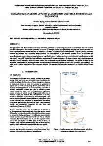
(c) North-South actual flight (d) East-West actual flight trajectory trajectory Figure 2. Graphical interface of the image capturing mission flight plan designed to cover a study area. 3.3 Novel Automatic UAV Image-based Registration
(a) (b) Figure 1. The GoPro Hero 3+ Black Edition camera (a) and the DJI Phantom II UAV drone system (b). 3.2 Mission Planning and Data Collection The departure point of the proposed workflow is the acquisition of the time-series UAV image-based datasets. The quadcopter used in this study, equipped with an action digital frame camera, has a lens with a 3-mm nominal focal length. Image acquisition is performed at two flights in different directions (Figure 2) for every field campaign over a given study area. With the camera operating at the medium field-of-view mode, flight lines are shot at a data rate of 5 frames per second, at an altitude of roughly 30 m, at a speed of 5 m/s, resulting in a Ground Sample Distance (GSD) of roughly 2 cm. The GoPro is calibrated and tested for the stability of its internal characteristics using an indoor camera calibration test field and refined through an insitu camera calibration. The United States Geological Survey (USGS) simultaneous multiframe analytical calibration (SMAC) distortion model is employed within the calibration procedure. The camera calibration parameters consisted of the focal length (c), principal point offset (xp, yp), radial (k1, k2, and k3), and de-centric (P1 and P2) lens distortions (Al-Rawabdeh et al., 2016). The deviations of the linear path of the flight trajectories are depicted in (Figure 2c and d). All flights were performed in automatic mode in order to maintain level flights, control the altitude, log system data at 1 Hz (including platform position as measured with the on-board consumer-grade GPS),
A novel and robust procedure for the aligning of temporal UAV image-based point clouds to a reference frame is presented in this section. The primary contribution of this method is its adoption of the general bundle block adjustment for image registration for both dates in order to minimize geometric misalignment. The proposed registration procedure is performed using the SfM approach developed by He and Habib (2014). This approach automates the process of image EOP recovery and sparse point cloud generation with respect to the mapping reference frame, and is based on the following three-step strategy: 1) In the first step, the relative orientation parameters relating stereo-images are derived by using the coplanarity equations, where the closed-form Nistér five-point approach is used for the approximate values (Nistér, 2004). In this research, these conjugate point features are automatically identified through a SIFT detector and descriptor (Lowe, 2004). 2) Once the ROPs of all possible stereo-pairs are estimated, an incremental approach, which is developed by He and Habib (2014), is adopted for the initial recovery of the image EOPs. Specifically, this incremental approach is initiated by defining a local coordinate frame. Then, all the images are sequentially augmented into a final image block or trajectory. 3) Since the derived sparse point cloud from the SfM approach is only defined in an arbitrary local coordinate system, an absolute orientation process has to be applied for transforming the derived point cloud as well as the estimated image EOPs relative to the mapping reference frame. In this research, using the GPS measurements, which are recorded at each image exposure time by a consumer-grade GPS receiver mounted on the utilized UAV platform, and the image
This contribution has been peer-reviewed. doi:10.5194/isprsarchives-XLI-B1-765-2016
768
The International Archives of the Photogrammetry, Remote Sensing and Spatial Information Sciences, Volume XLI-B1, 2016 XXIII ISPRS Congress, 12–19 July 2016, Prague, Czech Republic
positions that are derived from the proposed SfM approach, the absolute orientation process is performed for the estimation of the 3D Helmert transformation parameters (i.e., scale factor, three translation parameters, and three rotation angles) relating the two involved coordinate systems. Now that the absolute orientation process is completed, a global bundle adjustment with GCPs is finally applied to refine the estimated parameters in the mapping reference frame. 3.4 Evaluation of Proposed Registration Method Qualitative and quantitative quality control procedures were performed for an evaluation of the estimated registration results of the proposed method in order to register two or more 3D image-based point cloud datasets. Additionally, a quantitative quality control method was proposed for evaluating the registration results by calculating the point-to-plane normal distances between the registered surfaces. Qualitative quality control is achieved by plotting together all the generated 3D dense image-based point clouds with respect to the same reference coordinate system. By examining the registered datasets more closely, the quality of the proposed registration method is evaluated, and a more detailed analysis is conducted using overlapping, stable, non-active areas between the 3D dense image-based point cloud datasets. Since the overlap area is affected by a landslide, in this research quantitative quality controls of the registration method is necessary. In this case, the accuracy of the co-registered surfaces was estimated by comparing non-active patches within the monitored area of interest. Since these non-active, sub-areas are stationary, two surfaces generated at different epochs should, theoretically, be close to each other. The quantitative quality control process is based on point-toplane normal distances. These distances are calculated between registered point clouds generated using the proposed registration method, and are calculated as follows: Two 3D image-based points cloud datasets are registered into the same reference coordinate system using the proposed method via a bundle block adjustment. Conjugate planes in non-active areas (i.e., building roofs) are determined manually (Figure 3a), while stable bare earth surfaces (see Figure 3b) are determined automatically based on the ICProxalgorithm proposed by Wujanz et al. (2016). Root Mean Square Error (RMSE), mean, and standard deviation of the calculated point-to-plane normal distances for each plane, are calculated.
4. EXPERIMENTAL RESULTS In this section, the experimental results of the proposed registration method are presented. The results are evaluated qualitatively as well as quantitatively. 4.1 Data Description A flight campaign was performed in May 2014 and again in May 2015 using a low-cost customized multi-rotor DJI phantom II UAV. Each autonomous flight was planned at an altitude of 25-30 m above ground level (AGL) at a speed of 5 m/s for each of the four flight missions (Figure 2; Table 1) during the two separate field campaigns at an active soil creep site in Lethbridge, Alberta, Canada. The study area was covered following a grid of parallel and perpendicular flight lines (North-South and East-West) ensuring that each ground object was imaged in the along- and across-track directions of the UAV platform for maximizing overlap, and in order to allow for an in-situ self-calibration network geometry. The flights over the study area covered an area of approximately 0.04 km2. The GSD achieved was 2 cm at the given altitude. Table 1. Overview of all UAV flights performed for study area Site III, Lethbridge, Alberta in May 2014 and May 2015. Flight date May 2014 May 2015
Area covered [km2] 0.0317 0.0387 0.0307 0.0387
Flight direction
Duration [min]
N-S E-W N-S E-W
11.23 8.57 12.08 9.35
No. of images taken 497 500 602 639
No. of images used 387 325 411 420
(a)
(b) Figure 4. Sample set of UAV images of the experimental dataset: (a) and (b) showing image sequences image with 80% overlap along the flight path as well showing the 70% sidelap between adjacent flight paths. 4.2 3D Surface Reconstruction
(a) Selected building roof tops (b) Selected stable area surfaces Figure 3. Selected patches using in estimate quantitative quality control.
The proposed procedure using the adopted SfM for the automated EOPs recovery is tested using both image datasets coming from two periods within the global bundle block adjustment as one processing unit. Within the SfM procedure, 712 from the original set of 997 taken in May, 2014, and 831 from the 1241 images taken in May, 2015 for the Lethbridge study area were selected after blurred and highly redundant images were removed. As summarized in the Table 2, for both image datasets, the image re-projection errors tend to be approximately one pixel. These results indicate that the EOPs estimated through the proposed procedure are accurate. Conversely, because the two available image datasets for the
This contribution has been peer-reviewed. doi:10.5194/isprsarchives-XLI-B1-765-2016
769
The International Archives of the Photogrammetry, Remote Sensing and Spatial Information Sciences, Volume XLI-B1, 2016 XXIII ISPRS Congress, 12–19 July 2016, Prague, Czech Republic
experiments are taken at different times, results also indicate that the proposed procedure can also handle sets of collected images from different times. Table 2. Bundle block adjustment results using the images from both observational epochs No. of images Average flying altitude Ground sampling distance
1,543 25-30 m 0.02 m/pix
No. of tie points Image space error Covered area
1,054,494 1.33 pix 0.044 km2
The dense point clouds generated for the Kings Park site in Lethbridge were made of more than 18 million (May 2014) and 19 million (May 2015) points. The density of these point clouds is approximately 400 points per square metre (m2) and the point cloud results, i.e., the outputs from the visualization algorithm from the different periods, are shown in Figure 5.
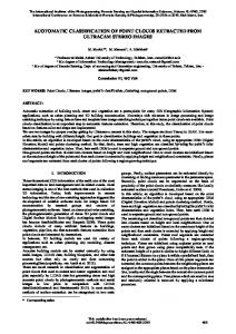
Figure 5. Perspective view of the colourized dense 3D UAV image-based point cloud generated using the SGM algorithm, the point cloud from the image sets captured on May, 2014 (left) and the point cloud from the image sets captured on May, 2015 (right). 4.3 Quality Control of the Registration Results The quality control of the registration results was evaluated and is presented qualitatively and then quantitatively in the following subsections. 4.3.1 Qualitative Quality Control Registration results were evaluated through a qualitative quality control, involving plotting the 3D dense image-based point cloud surfaces together. Figure 6 illustrates the general view of the two registered surfaces over one year, coloured based on date of image capture. The right side represents the point cloud generated on May, 2014, while left side represents the point generated on May, 2015, and the fact that the datasets are correctly aligned to each other is obvious. For a more detailed analysis of the results closer examination of the registered dense point clouds was required. Given that most of the overlap areas between the two datasets were affected by a landslide, only a few overlapping parts of the two registered datasets were closely evaluated. Common features present in the overlap areas, such as the building’s roof top in the registered datasets, are illustrated in Figure 7. In this figure, each colour indicates a 3D image-based point cloud generated at a different time. Figure 7 displays the registration result of the selected parts of the roof top based on the proposed registration method. Again, the successful registration between the point clouds from the two periods is clearly visible.
Figure 6. Top view of the visual comparison for two registered image-based point clouds of the landslide area in Kings Park, Lethbridge, Alberta.
Figure 7. Registration results based on the proposed registration method for a part of the Lethbridge landslide area. A cross-sectional view of the same sections between the generated point clouds is shown in Figure 8, providing a better visualization of the registration results. As illustrated in Figure 8, the 3D dense image-based point clouds are well-registered using the proposed method.
Figure 8. Registration results using the proposed methodology of a cross-section diagonally across the Lethbridge landslide area between the epoch from 2014 (red) and the epoch captured in 2015 (blue). 4.3.2 Quantitative Quality Control The quantitative analysis of registration results was achieved by calculating the point-to-plane normal distances for the selected planes between the generated two 3D image-based point cloud surfaces over one year. Using the proposed registration method, all the dense point cloud surfaces were transformed using a common coordinate system. The calculated mean, standard deviation, and RMSE of the point-to-plane normal distances between the two sets of point clouds are presented in Table 3.
This contribution has been peer-reviewed. doi:10.5194/isprsarchives-XLI-B1-765-2016
770
The International Archives of the Photogrammetry, Remote Sensing and Spatial Information Sciences, Volume XLI-B1, 2016 XXIII ISPRS Congress, 12–19 July 2016, Prague, Czech Republic
Table 3. The mean, standard deviation and RMSE of the calculated normal distances resulted from the proposed registration method for the stable patches between 3D dense image-based point clouds generated from May, 2014 and May, 2015 of the study area in Lethbridge, Alberta. Registration Method Proposed Method
Statistics [cm] Mean Standard deviation RMSE
Building roof tops 0.086 1.520 1.530
Stable area surfaces 2.490 2.730 3.690
zero. The quality control of the registration results showed that the average normal distance was approximately 4 cm, which is within the noise level of the reconstructed surfaces. Overall, it can be concluded that the proposed registration approach is low level, i.e., the registration is performed at the image/bundle adjustment level as opposed to the point cloud level. The produced results are suitable for use in the field of landslide research.
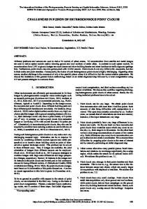
ACKNOWLEDGEMENTS Analysis of the normal distance results for each of the selected patches indicates that the proposed registration method is capable of achieving an accurate alignment between the multitemporal point clouds. The mean, standard deviation, and RMSE of the calculated point-to-plane normal distances of each sample patches were all below 4 cm, substantiating the quality of the registration results seen in Table 3. However, the results of the calculated normal distances using the points of the building roofs top, located in the region of the stable area and unaffected by vegetation growth are generally smaller than the calculated normal distances using all the points of the selected stable ground area. And finally, a visual illustration of the calculated point-to-plane normal distances was done by plotting the point clouds over one year, using colour and based on the normal distance Figure 9. From this, it can be concluded that for the proposed method, the datasets are registered with a high degree of precision.
(a) Building roof tops (b) Stable area surfaces Figure 9. Top view of the selected patches for quantitative quality control in the two registered datasets (colours represent calculated normal distances).
5. CONCLUSIONS In this study, a practical approach for detecting change with a high degree of precision in multi-temporal, image-based point clouds was presented. The dense 3D point cloud data was generated after flying the area of interest with a low-cost UAV, and the method proposed was robust and automated. This is paramount in order to evaluate the effectiveness of change detection for identifying and quantifying movement in areas of erosion or deposition caused by rain events, as well as regularly updating topographic data in landslide areas prone to rapid change. The proposed approach can easily handle a large number of images from different epochs and enables the provision of registered image-based point clouds without the use of extensive ground control point information. The accuracy of the co-registered surfaces was estimated by comparing non-active patches within the monitored area of interest. Since these non-active sub-areas are stationary, the computed normal distances should theoretically be close to
The authors are grateful to Yarmouk University in Jordan for financing the first author’s scholarship at the Department of Geomatics Engineering in University of Calgary, Canada. This work was supported also by Dr. Naser El-Sheimy research funds from NSERC and Canada Research Chairs programs. The authors are grateful also to Daniel Wujanz (Department of Geodesy and Geoinformation Science, Berlin Institute of Technology) who processed the data using ICProx-algorithm to automatically extract the stable area surfaces.
REFERENCES Al-Durgham, K. & Habib, A., 2014. Association-Matrix-Based Sample Consensus Approach for Automated Registration of Terrestrial Laser Scans Using Linear Features. Photogrammetric Engineering & Remote Sensing, 80(11), pp.1029–1039. Al-Durgham, M. & Habib, A., 2013. A framework for the registration and segmentation of heterogeneous LiDAR data. Photogrammetric Engineering & Remote Sensing, 79(2), pp.135–145. Al-Rawabdeh, A.; He, F.; Moussa, A.; El-Sheimy, N.; Habib, A., 2016. Using an Unmanned Aerial Vehicle-Based Digital Imaging System to Derive a 3D Point Cloud for Landslide Scarp Recognition. Remote Sens. 8, 95. Al-Manasir, K. & Fraser, C.S., 2006. Registration of Terrestrial Laser Scanner Data Using Imagery. The Photogrammetric Record, 21(115), pp.255–268. Bae, K.H. & Lichti, D.D., 2008. A Method for Automated Registration of Unorganised Point Clouds. ISPRS Journal of Photogrammetry and Remote Sensing, 63(1), pp.36–54. Besl, P. & McKay, N., 1992. A Method for Registration of 3-D Shapes. IEEE Transactions on Pattern Analysis and Machine Intelligence, 14(2), pp.239–256. Chen, Y. & Medioni, G., 1991. Object Modelling by Registration of Multiple Range Images. Proceedings. IEEE International Conference on Robotics and Automation, (April), pp.2724–2729. El-Sheimy, N., 2005. An overview of mobile mapping systems, in: From Pharaohs to Geominformatics. Presented at the FIG Working Week 2005 and GSDI-8, Cairo, Egypt, pp. 1– 24. Gielsdorf, F., Gruendig, L., Milev, I., 2008. Deformation Analysis With 3D Laser Scanning. Proceedings of the 13th FIG Symposium on Deformation Measurement and Analysis, Lisbon, Portugal. Gruen, A. & Akca, D., 2005. Least Squares 3D Surface and Curve Matching. ISPRS Journal of Photogrammetry and Remote Sensing, 59(3), pp.151–174. Habib A., A. P. Kersting, Z. Ruifanga, M. Al-Durgham, C. Kim, and D. C. Lee., 2008. LiDAR Strip Adjustment Using Conjugate Linear Features in Overlapping Strips.
This contribution has been peer-reviewed. doi:10.5194/isprsarchives-XLI-B1-765-2016
771
The International Archives of the Photogrammetry, Remote Sensing and Spatial Information Sciences, Volume XLI-B1, 2016 XXIII ISPRS Congress, 12–19 July 2016, Prague, Czech Republic
The International Archives of the Photogrammetry, Remote Sensing and Spatial Information Sciences. Vol. XXXVII. Part B1. Beijing 2008 . pp. 386-390. Habib A., I. Detchev, and K. Bang, 2010. A Comparative Analysis of Two Approaches for Multiple-Surface Registration of Irregular Point Clouds. International Archives of the Photogrammetry, Remote Sensing and Spatial Information, XXXVIII (Part1). Habib, A., Bang, K.I., Kersting, A.P., Chow, J., 2010. Alternative Methodologies for LiDAR System Calibration. Remote Sens. 2, 874–907. doi:10.3390/rs2030874. He, F. & Habib, A., 2014. Linear Approach for Initial Recovery of the exterior orientation parameters of randomly Captured Images by Low-cost Mobile Mapping Systems. International Archives of the Photogrammetry, Remote Sensing and Spatial Information Sciences - ISPRS Archives, 40(1), pp.149–154. Immerzeel, W.W. et al., 2014. High-Resolution Monitoring of Himalayan Glacier Dynamics Using Unmanned Aerial Vehicles. Remote Sensing of Environment, 150, pp.93– 103. Jaw, J. & Chuang, T., 2008. Feature-Based Registration of Terrestrial Lidar Point Clouds. International Archives of the Photogrammetry, Remote Sensing and Spatial Information Sciences (IAPRS), XXXVII (Part B3b), pp.303–308. Kang, Z. & Lu, Z., 2011. The Change Detection Of Building Models Using Epochs of Terrestrial Point Clouds. International Workshop on Multi-Platform/Multi-Sensor Remote Sensing and Mapping, M2RSM 2011, XXXVIII, pp.231–236. Kang, Z., Li, J., Zhang, L., Zhao, Q., Zlatanova, S., 2009. Automatic Registration of Terrestrial Laser Scanning Point Clouds using Panoramic Reflectance Images. Sensors, 9(4), pp.2621–2646. Kwak, T.S., Kim, Y.I., Yu, K.Y., Lee, B.K., 2006. Registration of Aerial Imagery and Aerial Lidar Data Using Centroids of Plane Roof Surfaces as Control Information. KSCE Journal of Civil Engineering, 10(5), pp.365–370. Lari, Z., & El-Sheimy, N., and Habib, A., 2015. System Considerations and Challenges in 3D Mapping and Modelling Using Low-Cost UAV Systems. The International Archives of Photogrammetry, Remote Sensing and Spatial Information Sciences, 40(3), 343. Liang, Y.-B., Zhan, Q. M., Che, E. Z., Chen, M. W., Zhang, D. L., 2014. Automatic Registration of Terrestrial Laser Scanning Data Using Precisely Located Artificial Planar Targets. IEEE Geosci. Remote Sens. Lett. 11, 69–73. doi:10.1109/LGRS.2013.2246134. Lichti, D.D. and Skaloud, J., 2010. Registration and Calibration. In Airborne and Terrestrial Laser Scanning, G. Vosselman and H.-G. Maas (Eds.). Whittles Publishing: Caithness, UK, 83-133. Lowe, D.G., 2004. Distinctive Image Features from Scale Invariant Keypoints. Int’l Journal of Computer Vision, 60, pp.91–110. Lucieer, A., Turner, D., King, D. H., & Robinson, S. A., 2014. Using an Unmanned Aerial Vehicle (UAV) to Capture Micro-topography of Antarctic Moss Beds. International Journal of Applied Earth Observation and Geoinformation, 27, 53-62. Matabosch, C., Salvi, J., Fofi, D., Meriaudeau, F., 2005. Range Image Registration for Industrial Inspection, in: Electronic Imaging 2005. International Society for Optics and Photonics, pp. 216–227 Murakami, H., Nakagawa, K., Hasegawa, H., Shibata, T., &
Iwanami, E., 1999. Change Detection Of Buildings Using an Airborne Laser Scanner. ISPRS Journal of Photogrammetry and Remote Sensing, 54(2-3), 148–152. Nistér, D., 2004. An Efficient Solution to The Five-Point Relative Pose Problem. Pattern Anal. Mach. Intell. IEEE Trans. On 26, 756–770. Rabbani T., S. Dijkman, F. Heuvel, and G. Vosselman., 2007. A Review Of Recent Range Image Registration Methods with Accuracy Evaluation. Image and Vision Computing, 25(5), pp.578–596. Salvi, J., Matabosch, C., Fofi, D., & Forest, J., 2007. A Review of Recent Range Image Registration Methods With Accuracy Evaluation. Image and Vision Computing, 25(5), 578–596. Schuhmacher, S. & Böhm, J., 2005. Georeferencing of Terrestrial Lasers Scanner Data for Applications in Architectural Modelling. 3D-ARCH 2005: Virtual Reconstruction and Visualization of Complex Architectures, XXXVI, p.7. Schürch, P., L. Densmore, A., J. Rosser, N., Lim, M., W. McArdell, B., 2011. Detection of Surface Change In Complex Topography Using Terrestrial Laser Scanning: Application to The Illgraben Debris-Flow Channel. Earth Surface Processes and Landforms, 36(14), pp.1847–1859. Singh, A., 1989. Review Article Digital Change Detection Techniques Using Remotely-Sensed Data. International Journal of Remote Sensing, 10(6), pp.989–1003. Tombari, F. & Remondino, F., 2013. Feature-Based Automatic 3D Registration for Cultural Heritage Applications. Proceedings of the Digital Heritage 2013 - Federating the 19th Int’l VSMM, 10th Eurographics GCH, and 2nd UNESCO Memory of the World Conferences, Plus Special Sessions from CAA, Arqueologica 2.0 et al., 1, pp.55–62. Tsakiri M., and Anagnostopoulos, A., 2015. Change Detection of Buildings Using An Airborne Laser Scanner. ISPRS Journal of Photogrammetry and Remote Sensing, 54(2-3), pp.148– 152. Turner, D., Lucieer, A. & de Jong, S.M., 2015. Time Series Analysis of Landslide Dynamics Using An Unmanned Aerial Vehicle (UAV). Remote Sensing, 7(2), pp.1736–1757. Vögtle, T. & Steinle, E., 2004. Detection And Recognition of Changes In Building Geometry Derived From MultiTemporal Laser Scanning Data. International Archives of the Photogrammetry, Remote Sensing and Spatial Information Sciences, 34, pp.428–433. Walter, V., 2004. Object-Based Classification of Remote Sensing Data for Change Detection. ISPRS Journal of Photogrammetry and Remote Sensing, 58(3-4), pp.225–238. Wang, Q. et al., 2014. Accuracy Evaluation of 3D Geometry From Low-Attitude UAV Collections A Case At Zijin Mine. In ISPRS - International Archives of the Photogrammetry, Remote Sensing and Spatial Information Sciences. pp. 297– 300. Wen, C., Qin, L., Zhu, Q., Wang, C., Li, J., 2014. ThreeDimensional Indoor Mobile Mapping With Fusion of TwoDimensional Laser Scanner and RGB-D Camera Data. IEEE Geosci. Remote Sens. Lett. 11, 843–847. doi:10.1109/LGRS.2013.2279872. Wilkinson, B.E., Mohamed, A.H., Dewitt, B.A., Seedahmed, G.H., 2010. A Novel Approach to Terrestrial LiDAR Georeferencing. Photogramm. Eng. Remote Sens. 76, 683– 690. Wujanz, D., 2012. Towards Transparent Quality Measures In Surface Based Registration Processes: Effects of Deformation Onto Commercial and Scientific Implementations. In in: Proceedings of the XXII Congress of the International Society of Photogrammetry and Remote Sensing, Melbourne, Australia. Y. Reshetyuk., 2010. Direct georeferencing with GPS in terrestrial laser scanning, ZfV 135, 151–159.
This contribution has been peer-reviewed. doi:10.5194/isprsarchives-XLI-B1-765-2016
772