and three bones (the ossicular chain) in an air filled bony cavity, as shown below: ...... Kroll K, Grant IL, Javel E. The Envoy totally implantable hearing system, ...
Implantable Hearing Aids Abstract The aim of this article is to acquaint readers with some of the concepts involved in the latest generation of implantable hearing aids. These devices have been developed over the last 20 years, driven by a perceived demand amongst patients and by advances in the understanding of middle ear mechanics. The use of technology borrowed from cochlear implants has enabled the first generation of fully implantable aids to be trialled. This article examines the theoretical advantages and disadvantages of implantable hearing aids over conventional aids and then reviews the technology and clinical results of the current range of devices.
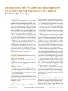
Summary of Ear Mechanics The human ear is designed to allow useable hearing between 200Hz-10kHz. It is traditionally divided into three sections; the outer, middle and inner ear, each of which has a different function, as shown below.
Directionality & Gain
Impedance matching
Transformer mechanical electrical
Figure 1 Basic Ear Anatomy
The Outer Ear This consists of the pinna, i.e. the visible part on the side of the head, and the external ear canal (EAC), the tube leading to the middle ear. The shape of the pinna and the resonance of
1
the EAC give around 15dB gain between 1-4kHz. This is the area in which most information is carried in speech, and is therefore the most valuable frequency range to humans.
The Middle Ear This is essentially an impedance matching device to allow air vibrations to be efficiently transmitted to the fluid of the cochlea. It consists of the eardrum (tympanic membrane – TM) and three bones (the ossicular chain) in an air filled bony cavity, as shown below: Stapes Ossicular chain
Incus Malleus
Tympanic membrane
Figure 2 Tympanic membrane and ossicular chain
The TM is a thin (60m) fibrous diaphragm 8-10mm in diameter and slightly conical. It is attached to the outermost of the three middle ear bones and vibrations are transmitted via the ossicular chain to the footplate of the stapes which sits in the oval window. The lowest threshold of hearing results in a movement of around 0.1nm at the stapes footplate and very loud sounds about 10m. It is the difference in area between the TM (60mm2) and the oval window (3mm2) which creates the vast majority of the impedance matching. The ossicular chain does have two joints, but tends to move as a rigid body at acoustic frequencies. Changes in atmospheric pressure can cause the TM to move by up to 2mm, the joints allow the TM and oval window to remain connected without the stapes becoming jammed at one end of its range of movement. The other significant structure connected to the middle ear is the Eustachian tube. This allows equalisation of the air pressure either side of the TM to allow for maximum sensitivity of the ear.
The Inner Ear The inner ear consists of a complex bony cavity subdivided into different fluid filled compartments. It transforms mechanical forces into electrical signals which are transmitted via the auditory nerve to the brain. The part of the inner ear known as the vestibular system is concerned with balance and transforms the forces generated by gravity and rotational acceleration of the head. The remainder of the inner ear (the cochlea) transforms the vibrations caused by motion of the stapes in the oval window. It is arranged so that the fluid filled space wraps around both sides of a long membrane. This membrane is thicker and narrower near the oval window and gradually thins and widens towards the other end. This design enables different parts of the membrane to resonate at different frequencies and motion 2
sensitive cells distributed along its length will therefore respond to different frequencies, thus enabling frequency discrimination. In order that the stapes is not trying to compress fluid within a rigid bony cavity there is a second opening into the middle ear, called the round window, which moves reciprocally with the oval window. To ensure that the cochlea is able to fit in the skull, the whole design is coiled up into a spiral, much like a snail shell.
Vestibular System
Figure 3 The Inner ear
Hearing loss and hearing aid usage Hearing loss is a very common disability. There are 42 million people over 16 in the UK; of these 16% have hearing difficulties, but only 4% use a hearing aid. This leaves 12% (5 million people) with an untreated hearing problem 1. Of the 1.5 million who use an aid, 62% report continued difficulties with their hearing. Around 58000 people have working hearing aids that they do not use1. Even those people that use their aid do so for a mean of around 3 hours per day 2.
Factors affecting hearing aid use There are many reasons for the low uptake and usage rate 3 & 4. The following are found to be the most important factors that can be affected by hearing aid design: 1. Stigma/Cosmesis. The hearing aid is very commonly seen as a visible sign of disability, which naturally leads to low uptake and usage. The stigma itself can be due to a number of different issues relating almost exclusively to the appearance of the hearing aid and the patient’s expectations of other people’s reaction to the aid. None of these factors would be a significant issue for the patients if the aid were not visible. 2. Discomfort. Traditional hearing aids have a mould which fits into the outer ear. This is made from a silicone cast of the patients ear canal, but the process of creating the mould from the cast is an inexact science, and thus a significant proportion of patients suffer from discomfort in their ear canal. The recent application of rapid prototyping techniques5 has changed this to some extent, but many patients still
3
complain of discomfort. This has a variable but significant impact on the duration for which a hearing aid is used. In a conventional aid, the fit also has a significant influence on the next factor. 3. Feedback. The close proximity of the speaker and the microphone often leads to acoustic feedback, which generates the annoyingly familiar high pitched whistle often heard near a hearing aid user. The feedback loop can be broken by improving the seal between the ear and the hearing aid mould (Fig. 5, point 1) or by designing adaptive circuitry within the aid that detects and then removes the frequencies responsible (Fig. 5, point 2) 6. This does however have some impact on sound quality. Sound “leaking” back to microphone
Amplifier
1 1
2 2
Microphone
Loudspeaker
Figure 4 Acoustic feedback loop The energy flow in an acoustic feedback loop follows the blue arrows and is boosted at every pass by the amplifier. It may be halted by a better seal at point 1 or by an electronically tuned filter at point 2.
It is also possible to place the microphone and the loudspeaker physically further apart so that any sound leakage is attenuated by distance. This is the principle behind body worn aids, where the microphone, amplifier and battery are in a box worn hung around the neck. These are typically used where very high degrees of amplification are required. Acoustic feedback often means that patients will turn the gain of their aid down to a sub-optimal level, and therefore have sub-optimal hearing, rather than risk repeated episodes of feedback. It is therefore an important issue in the difference between the theoretical performance of an aid and its actual benefit to a patient. 4. Difficulty controlling the aid. The cosmetic drive towards smaller and smaller aids has made the controls of hearing aids harder and harder to manipulate. The elderly in particular find hearing aid controls difficult to use and, if they also have arthritis in their finger joints, it can be impossible for them to use the controls.7 This problem has been somewhat ameliorated by the new generation of digital aids, which have automatic circuitry within them that attempts to adjust the amount of amplification and its frequency pattern, depending on the ambient background noise. This reduces the need for the patient to adjust their aid manually. 5. Occlusion effect. A standard hearing aid, of necessity, has an ear mould which inserts in the external ear canal. This occludes the canal and leads to a significant change in hearing8. This effect is caused by a combination of different factors: a. A reduction in the amount of high frequency sound entering the ear as the canal is now blocked by the hearing aid mould; b. The resonance properties of the ear canal are changed by placing the mould in it
4
c. There is a natural high pass filter effect from the ear canal due to the mass effect and compliance of the column of air contained within it. These three effects together lead to a drop in high frequency air conducted hearing and a marked low frequency emphasis of bone conducted hearing, as shown in Fig. 6. The practical upshot is that patients notice a marked low frequency emphasis of their own voice which many find unpleasant and lead them to stop using their aid.
Figure 5 Sound pressure in the intact ear canal when stimulation is by BC at the mastoid The solid line shows the results when the ear canal is open and the dashed line shows the results when the ear canal is occluded by a glass cover at the ear canal opening. The vertical bars indicate ±1 standard deviation of the measurements. (From Stenfelt and Goode, 2005. With permission)
The above factors have driven the search for a more acceptable hearing aid. Miniaturisation of electronics has enabled totally in the canal aids to be made, which have reduced the visibility and hence the stigma of wearing hearing aids. It has, however, made feedback more likely, made aids harder to control and had little effect on discomfort or the occlusion effect. Partially or totally implantable aids are now becoming available. These devices require an operation to implant them in the patient but completely remove problems with stigma, occlusion and discomfort. Control of the aid has to be done remotely which, whilst initially seeming to be a drawback, actually allows for much more flexibility in the design of the controller. Rather than being constrained by the dimensions of the hearing aid, the controls can be designed to enable use by a person with limited finger mobility. It is also be possible to design different controllers to meet different patient needs. Acoustic feedback is very dependant on the exact design of the implant, in particular the positioning of the output transformer relative to both the microphone and the different structures within the ear. An implanted aid can also be worn whilst bathing or swimming. The major theoretical disadvantages of implanted aids are the requirement for an operation and their high cost in comparison to a conventional aid. The cost will undoubtedly come down as technology advances and the electronics become cheaper. The requirement for an operation will obviously remain, but many patients accept this requirement in order to gain the advantages of an implanted aid, indeed other types of voluntary surgery, e.g. aesthetic plastic surgery, have seen a steady increase over the last few years9. The implantation procedure is becoming simpler with time10 11, both as a result of surgical technique and device design. The relative advantages and disadvantages are summarised in the table below: 5
Type of Aid
Conventional
Miniaturised conventional
Partially implantable
Fully implantable
1. Stigma/Cosmesis
Yes
Improved
Yes
No
2. Discomfort
Yes
Yes
No
No
3. Feedback
Yes
Worsened
4. Difficulty with control
Yes
Worsened
Design dependant Design dependant
Design dependant Design dependant
5. Occlusion effect
Yes
Yes
No
No
6. Operation required
No
No
Yes
Yes
Problem
Table 1 Drawbacks of different types of hearing aid
Hearing aid design One of the major impediments to a totally implantable aid is how to get the sound energy to the cochlea. The output transducer of almost all aids that fit into the ear canal is, in essence, a loudspeaker. The flow of vibration energy to the cochlea is therefore as shown below:
Speaker
Air
Ear Drum
Ossicular Chain
Cochlea
Figure 6 Energy flow in standard hearing aid
The difficulty with this is that there are a large number of interfaces across which vibration must be transmitted. Transmission of vibration across any interface is always associated with some loss if energy and also some distortion of the vibration. This is particularly true if the vibration is being transferred between media of widely differing physical properties such as air to solid or vice versa. As an illustration, the characteristic impedance of air is 407Ns/m3, water is 1.5x10⁶Ns/m312 and bone is 2.4x10⁶Ns/m313. This causes a bigger problem at higher frequencies, which is just where the majority of people have their hearing loss. In a conventional aid this transfer is happening twice; from the solid of the speaker cone to the air and then again from air to the solid tympanic membrane. Whilst good engineering design can minimise the energy loss and distortion it can never be eliminated. There is also a problem with the physical size of the speaker contained in a conventional hearing aid. It is, of necessity, very small and thus has a poor frequency response, leading to a loss of signal output at high frequencies. This is shown below:
6
Figure 7Frequency response of a typical hearing aid speaker. The response drops off dramatically above 3kHz, and is of no practical value above 5.5kHz
These difficulties have led to a search for an improvement in the means of transmitting vibration to the cochlea, and thus an improvement in the efficiency and fidelity of implantable hearing aids. The most sensible solution is to transmit vibrations directly to one of the last elements in the above chain of events. The picture therefore changes to this:
Output Transducer
Ossicular Chain
Cochlea
Figure 8 Energy flow in implanted aid
or this:
Output Transducer
Cochlea
Figure 9 Alternative energy flow in implanted aid
These are much shorter chains of events and thus reduce energy loss and distortion. Therefore, even if the transducer is used as part of a semi implantable hearing device as opposed to a fully implantable one, there are significant advantages to the patient in terms of sound quality and canal occlusion. Unfortunately, with this solution comes a further problem; how can the vibration be transferred?
Disadvantage of most current systems- energy losses The ultimate aim of any hearing device is to deliver energy to the cochlea. Current systems which attach to the ossicular chain have a fundamental drawback; some of the energy which they produce is diverted to the tympanic membrane and dissipated there rather than being used to vibrate the cochlea. The energy flow is as shown below:
7
Output Transducer
Tympanic Membrane Figure 10
Ossicular Chain
Cochlea
Energy flow from ossicular device
The relative amount of energy flowing down the different arms of the figure will depend on the relative impedances. Some devices are now being implanted in the round window niche 14. This has a theoretical advantage, in that by stimulating the round window, all of the energy is transmitted through the cochlea. Some of it will still be dissipated at the tympanic membrane, but only after it has passed through the inner ear. The energy flow is as shown below:
Output Transducer Figure 11
Round Window
Ossicular Chain
Cochlea
Tympanic Membrane
Energy flow from round window device
In both cases some of the energy is dissipated via the tympanic membrane and emerges as measurable sound in the external auditory meatus (EAM). The amount of sound produced in the EAM for a given input level is known as the reverse transfer function (RTF). This sound can be put to practical use in a couple of ways: 1. It can be used to optimise the placement of the device at the time of insertion. The better placed a given device is, the more energy will be transferred to the ossicular chain and the greater the RTF will be. Thus the best possible placement can be assured by adjusting the attachment until the RTF is maximised. 2. Variations in the ossicular mechanics due to age, disease or growth patters can cause dips in the frequency response of implanted devices. These dips can be detected by measuring the RTF after the healing process has settled down. Any dips in the frequency response can be corrected by a corresponding boost in the amplifier. This has been shown to be better than the standard subjective tuning process normally used for hearing aids15.
History of ear implants The first practical attempt to improve hearing by using implants was BW Armstrong’s use of grommets in the early 1950s. Since that date progress has been steadily accelerating. 1956 saw Wullstein attempt the first ossicular replacement prosthesis (ORP)16, in 1957 Djurno & Eyries performed the first cochlear implant 17 and in 1958 John Shea began using polythene tubing to improve the results of his stapes surgery 18. The 1970s saw the development of workable ossicular replacement prostheses and contemporaneously House’s and Simmons’ work on cochlear implants developed a useable technique. At the same time patents began to be filed for implantable hearing aids. Over the next two decades these ideas were adapted and refined by a multitude of enthusiasts as more accurate data on the function of the ear became available. A useable middle ear implant to replace the output stage of a hearing aid had to wait until 1993, when Ball filed a patent 19 for his implant which subsequently developed into the Vibrant/Med-el Soundbridge. Since then there have been a large number of different
8
approaches to finding the best way to transmit mechanical vibration to the inner ear via an implant. All of these approaches have had to choose from the following options: 1. Fully vs. partially implantable. 2. Electromagnetic vs. piezoelectric driver. 3. Means of attachment to the ossicular chain.
Current Devices All of the commercially available devices consist of the same four elements as any other hearing aid: 1. An input transducer (traditionally a microphone, but not in every device) 2. An amplifier / signal processor 3. A battery 4. An output transducer The amplifier / signal processor and the battery draw very heavily on research performed for cochlear implants. They do have an impact on both the functioning of the device and the implantation procedure, but much less so than the two transducers. This article does not therefore consider them in great detail. In a fully implantable aid the whole package is inserted at operation. In a partially implantable aid the microphone, battery and the majority of the processing is typically placed in an external device which is held to the scalp by an implanted magnet and transmits a signal to the implanted part via an induction loop. The implanted part typically consists of a demodulator and the output transformer itself. Output transducers may be divided up by the mechanism by which they convert an electrical signal into a vibration. There are two broad categories: Electromagnetic Piezoelectric Electromagnetic devices have the advantage that the permanent magnet does not have to be physically in contact with the coil and can therefore be attached to a middle ear structure without being rigidly attached to anything else. Hence, provided the magnet is of relatively low mass, there is no significant impact on the vibration of the middle ear structures. The magnet may be mounted outside the coil (extra coil electromagnet - ECE), in which case spacing and orientation of both the magnet and coil is critical. The permanent magnet may also be mounted within the coils (intra coil electromagnet - ICE), but this restricts the design of the device. These devices naturally tend to work best at lower frequencies. Piezoelectric devices are inherently very efficient, simple and therefore reliable devices. They are good at reproducing high-frequency signals, which matches well with the most common form of hearing loss, that induced by old age. The disadvantage of piezoelectric devices is that they are inherently rigid so, if they are coupled between a mobile and a fixed part of the middle ear, they will damp the vibration of the middle ear when the device is turned off20. The majority of devices rely on either a diaphragm (DPZ) or a “spring board” (SPZ) arrangement:
9
Figure 12 Diaphragm Piezoelectric element (DPZ) Red arrows show movement when voltage is applied.
Spring board Piezoelectric element (SPZ)
A number of different ways of applying these drivers have been investigated and have led to a number of different devices.
Electromagnetic - ICE Vibrant Soundbridge (VSB) – Symphonics/Med El This is the most well established device, having been first patented in the USA in 199319. The first implantation was by Prof U Fisch in Zurich in September 1996. since when nearly 2000 patients have been implanted worldwide. It has therefore had the most research performed into its benefits. It works on the principle of a magnet loosely constrained between two springs (or elastic balls in fig. 13) and surrounded by two electrical coils. When a current is fed to the coils they cause the magnet and, by Newton’s third law, the coils to vibrate. The whole device is attached to the ossicular chain and thus this too is vibrated, causing movement of the cochlear fluid. This device is called a "Floating Mass Transducer" (FMT) and is a fairly successful attempt to reduce the inherent lower efficiency of the electromagnetic approach.
Figure 13
Floating Mass Transformer
10
The FMT is attached to the incus by a titanium clip, as shown below.
Figure 14
Attachment of FMT
This must be manually crimped round the bone, and the crimping force can markedly affect how well the device is secured to the incus and thus its efficiency at transferring vibration. The other difficulty with the crimping technique is that the end of the incus is often conical and the crimping attachment is basically cylindrical. In this situation the FMT can slip towards the end of the incus and become loose. Some surgeons have therefore resorted to using glue over the crimp to make a secure connection or to cutting the crimp into two separate arms and adjusting each individually. The use of glue does not appear to have any significant effect on the efficiency of energy transfer to the inner ear21. The mass of the FMT is only 25 mg, this minimises the effect on middle ear vibration22, but the effect remains measurable. It becomes measurable in vitro at 500Hz and then increases with frequency approaching a 10-20dB loss at 5 kHz. The damping effect is also very dependant on the exact position of the FMT relative to the incus 23. An integrity check may be performed after implantation of the device. A frequency sweep from 250-8000 Hz is played into the device and the output from the ear canal measured. The input and output are then compared to ensure they are the same. This check ensures that a loose connection is not missed. It is obviously not a direct measure of the energy entering the cochlea The VSB has been undergoing continuous development since its release. The processor has moved from an analogue device (Vibrant P) to a 2 channel digitally programmable analogue device (Vibrant HF) to a 3 channel digital device (Vibrant D) and is now using an 8 channel digital device (Vibrant Signia). These changes have all led to modest, but measurable improvements in the performance of the device 24-26. There has however been no significant change in the FMT itself. It is helpful if the patient can hear the sound quality of the device prior to surgery so that they can make an informed decision about implantation. The company have therefore produced a device called the direct drive simulator which is a flexible rod on the end of which is mounted an FMT. This is driven by an external amplifier which receives its signal from a CD player. The FMT is placed against the patient’s tympanic membrane by the ENT surgeon and the patient is then able to experience the sound quality of the device. Drawbacks 1. The surgery required for this device, in particular the facial recess approach, means that there is a risk of damage to a nerve in the ear. Disruption of this nerve causes a change in the sensation of taste for the patient. Studies have reported various injury rates between 1.6% 27 and 15% 28. 2. As stated above, there is a small but measurable damping effect on the middle ear.
11
3. The device must be free floating, so if the middle ear contains scar tissue or is very small it can be very hard, or impossible to position the device correctly. 4. It is theoretically possible that the long process of the incus can become eroded by the attachment of the FMT. In practice this complication has not actually been seen. 5. It is possible to create a loose attachment and thus the device can be markedly reduced in efficiency. 6. Device failures are rare with the newer versions of the device29 but, due to its nature, if the electronics fail the whole device must be replaced. 7. The FMT itself contains a magnet. This is a cause for concern if the patient requires an MRI scan. Patients have been scanned at 1.5 tesla with no long term effects30. A loud “banging” noise was heard during the scan and a significant void was present in the images due to the magnet. One case of the FMT becoming displaced during a scan one year after implantation has been reported28. MET (FIMOS / Carina / Sonata) – Otologics This driver consists of an electric coil around a permanent magnet to which a rod is attached which drives the incus body. Studies of this device (both in vitro31 and in around 300 patients 32 ) show a very promising broadband, flat spectrum frequency response, but also confirm that the driver is somewhat awkward to place. Initially this was a semi-implantable device, with an externally mounted microphone. It has now been combined with a post-auricular implantable microphone, amplification and battery package and is a fully implantable system (initially called the “FIMOS”, then the “Sonata”, now the “Carina”) which is currently undergoing clinical trials in America. It is now available in Europe. The complete device is as shown below:
Figure 15
Otologics Carina
The placement surgery must allow the body of the incus to be exposed whilst still leaving enough of the skull to allow placement and fixation of the external metal fixing plate. The appearance at this stage of insertion is illustrated below:
12
External Ear Canal Mastoid drilling
External fixing plate
Skull Drilling
Figure 16
Surgery required for Otologics Carina
The main difficulty with the surgery is the requirement for very precise placement of a laser drilled hole in the incus body and then very precise placement of the tip of the metal rod in this hole; too much pressure causes splinting of the ossicular chain and thus a loss of amplification, whilst too little pressure results in inefficient transfer of vibration. Any misalignment of the rod and the hole also causes a loss of energy transfer. To ensure that the fitting is as accurate as possible, a device is provided that inputs a known, fixed input to the device and then measures the sound level in the external ear canal. This is known as the reverse transfer function. In essence, the optimal position of the tip of the device in the hole on the incus will cause maximum energy transfer and thus maximum sound in the ear canal. The audiological results of the system are very similar to that of the VSB, with no clinically significant difference between hearing with the Carina or a well fitted conventional digital hearing aid.
Electromagnetic - ECE SOUNDTEC Direct Drive Hearing System - Soundtec Inc This device works on a similar principle to the VSB, in that the medial part of the ossicular chain is driven electromagnetically. A permanent magnet is attached to the neck of the stapes and driven via a coil placed in a mould deep in the external ear canal. This does have the advantage of giving a higher fidelity signal than a standard hearing aid with less feedback, but it has some disadvantages: The incudo-stapedial joint must be disarticulated to allow the attachment loop of the magnet to be placed over the neck of the stapes. The joint is then rearticulated and tends to heal up very well. The patient has to wear a mould in the ear canal, which is one of the things that many patients complain of with a standard hearing aid. There is some evidence that the occlusion effect may be less than with a conventional mould33. It seems likely that this is due to the mould being much deeper than a normal hearing aid mould and thus having a different effect on ear canal resonance.
13
Titanium encased magnet
External ear canal driver with behind the ear electronics
Figure 17
Soundtec implant
Around 600 devices have been implanted since FDA approval in 2001, but the device is not currently available. One study34 showed that a proportion of patients noted increased vibration and noise production in areas of increased external magnetic fields (e.g. high tension power lines, televisions and security systems).This is obviously a significant concern for any implant employing a permanent magnet. The device has been shown to be stable in a 0.3 tesla open MRI scanner in 11 patients, but image degradation occurred at a radius of up to 4.3cm35 36. The mass of the implant is 27g, i.e. very similar to the VSB. It therefore has a very similar damping effect on the ossicular chain; with an average of 4.2dBHL conductive loss measurable across all 250-8000Hz after implantation37. The other main patient complaint about the system was the sensation of movement of the magnet. This was present in 43% of patients and increased to 50% when the external processor was not in use. The sensation was thought to be due to the magnet rotating about its single point of fixation to the ossicular chain. Due to a combination of these effects 6.25% (4/64) of patients demanded removal of the device and a further 4.7% (3/64) underwent reoperation to try to stabilise the magnet with fat. This procedure resulted in “partial improvement in symptoms”34. The device was therefore voluntarily withdrawn in 2004 pending redesign of the magnet attachment. SIMEHD – Cape Western Reserve University This device uses a permanent magnet attached to the body of the incus and a coil mounted very close to this in the middle ear cavity. Whilst it has been tested in animals with a reasonable outcome38, there is no obvious sign of it being used in a commercial device in the near future. It has the same problems as the other electromagnetic devices in that the positioning of the coil and the permanent magnet are critical to how well the device functions. The device therefore requires very precise, and somewhat fiddly, surgical implantation through a similar approach to the Otologics device. The magnet is attached to the body of the incus with a resin based glue39. The magnet and casing weigh 29g and thus, although no data are available, would be expected to have a very similar damping effect to the VSB and Soundtec devices.
14
Figure 18 SIMEHD Detailed view of titanium encased coil (1), titanium encased magnet (2) and incus (3).
Round Window Electromagnetic Device – University of Virginia This device works by the application of a permanent magnet to the round window membrane. The magnet is then driven by a coil placed within the mastoid cavity. The distance between the magnet and the coil is relatively large and therefore the efficiency of the device is not high. The concept of driving at the round window rather than the oval window has the benefit that there is a direct connection to the cochlear fluid, avoiding surgical procedures on the ossicular chain and leaving the normal acoustic pathway unaltered. It has been shown that the click evoked auditory brain stem response of guinea pigs is, if anything, slightly more efficient via the round window route then via the ossicular chain.40 Driving the cochlear via the round window also has the beneficial side effect of reducing the reverse transfer of energy through the ossicular chain to the tympanic membrane. This reduces the chance of feedback. Unfortunately further progress on this device appears to have been stalled by difficulties attaching a permanent magnet to the round window membrane.
Piezoelectric -DPZ Totally Integrated Cochlear Amplifier (TICA)- Cochlear/Implex AG This German system was the first fully implantable hearing device and received a CE mark in November 1999. It uses its piezoelectric diaphragm to drive the body of the incus via a metal rod and has a microphone implanted under the skin of the ear canal, as shown below:
15
Coupling rod
Polymer seal Titanium membrane
Piezoelectric ceramic disc
Hermetic seal
Figure 19
TICA driver
Implantation into the mastoid cavity is via a similar approach to the Otologics device but using a far bigger cavity to accommodate the larger device. The device has removable connectors from the driver and microphone into the battery/amplifier complex. In the event of a device failure it is therefore possible to replace any of the three component parts without disturbing the others. It has been implanted in approximately 20 patients with no significant side effects. Unfortunately the TICA has a low output at frequencies below 1.5kHz and one of the 20 patients withdrew from the study because the implant did not give him sufficient amplification 41. Difficulty with feedback meant that in order for the device to function properly a short segment of malleus neck needed to be removed in all of the patients studied. This obviously gave the patients a significant hearing loss whenever the device was turned off. This situation has been improved by modification of the software in the amplifier, but remains to be clinically proven in a significant number of patients. This device also suffered from a similar problem to the Otologics device in that placement of the driver rod on the incus must be extremely precise to avoid poor energy transfer. It is not currently available commercially, but the owners plan to develop it further soon.42
Piezoelectric -SPZ Partially Implantable Hearing Aid - Rion Ltd This was one of the earliest devices. It was developed in Japan and was only available in university research departments there. The driver was a long piezoelectric bimorph (SPZ) which was fixed via a metal bracket to the skull at one end and glue to the stapes head at the other. It initially gave a hearing improvement of around 36dB, but this declined over the course of a few months to 21dB. The device was implanted in 39 patients who all reported good benefit whilst the device was working properly, preferring it to their conventional aid 43.
16
ENVOY – St Croix Medical Inc. This system uses a piezoelectric transducer fixed within a mastoidectomy cavity by hydroxyapatite cement44. The transducer drives a rod which is connected to the head of the stapes by glass ionomeric cement. It is a fully implantable system which also uses a very similar piezoelectric device glued to the mastoid floor and the incus as an input transducer (the equivalent of the microphone in a normal hearing aid). It is currently still in clinical trials. Unfortunately, because it is both driving and sensing on the ossicular chain, it has enormous problems with feedback and requires the removal of the long process of the incus in order to prevent this. This obviously means that if the device is turned off the patient has a very large conductive hearing loss. The design of device used in the first trials showed a marked decline in performance over the 10 month period of the trial45. This was most likely to be due to a failure in the hermetic seal around the piezoelectric driver.
Other approaches A number of other variations on these techniques have been investigated. These include: Using MEMS technology to create extremely small coils allowing small permanent magnets to be placed very close to the coil in a very high current density46. Embedding superparamagnetic nanoparticles (i.e. extremely small silica coated particles of magnetite) in the middle ear epithelium covering the incus and then using an external coil to drive these in the same way as a permanent magnet47. Using a piezoelectric disk implanted in the extra-dural space to vibrate the cerebral spinal fluid and thus to excite the cochlear via an indirect fluid pathway48. Using a multilayer piezoelectric crystal cemented between the body of the incus and the skull wall49 50. Suspending a small magnet on the tympanic membrane with mineral oil and then driving this with an external coil either in the ear canal or on a lanyard around the neck. (Earlens system)51. Whilst all of these techniques have led to some very interesting results, they all have significant problems and are not currently incorporated into any commercial devices.
Conclusions from current devices Vast majority of these devices are targeted at the commonest form of hearing loss, that is presbycusis. They all suffer from the same problem to some extent which is that the alternative open to a patient with presbycusis is a conventional digital aid which is both much cheaper and far less invasive than any of the currently implantable devices. Whilst, by definition, an implantable device will require an operation, the current devices all require moderately complex surgery during which at least one of the components must be very precisely placed to achieve a good functional result. The surgery also exposes the patient to the risk of iatrogenic problems such as deafness and facial nerve or chorda tympani damage. These drawbacks somewhat limit the practical application of a very promising concept in hearing aid design.
17
Future progression The author feels there are a number of criteria which any new device or modification of an existing device should aim to meet in order to be more acceptable. These criteria have been placed in order of importance: 1. The risks to the patient’s hearing and nerves within the ear should be minimised. 2. It should not have a significant effect on the patient’s hearing if the device is turned off. 3. It should be implantable with as small an operation as possible. 4. Its placement should be tolerant of variations both in the patient’s anatomy and in the exact position achieved by the surgeon. 5. It should be as efficient as possible (to reduce battery drain and thus increase time between charges.) 6. It should produce as little feedback as possible.
18
Bibliography: 1. Rickards L, Fox K, Roberts C, Fletcher L, Goddard E. Living in Britain General Household Survey 2002. London: HMSO, 2004. 2. Maki-Torkko EM, Sorri MJ, Laukli E. Objective assessment of hearing aid use. Scandinavian Audiology 2001;30:81-82. 3. Brosch S, Michels L, Mauz PS, de Maddalena H, Lowenheim H. Factors influencing rehabilitation after sensorineural hearing loss with hearing aids. Hno 2005;53(2):142-147. 4. Kochkin S. MarkeTrak III: Why 20 million in US don't use hearing aids for their hearing loss. The Hearing Journal 1993;46(1). 5. Tognola G, Parazzini M, Svelto C, Ravazzani P, Grandori F. Three-dimensional laser scanning and reconstruction of ear canal impressions for optimal design of hearing aid shells. Proceedings of SPIE 2003;5009:19. 6. Shusina NA, Rafaely B. Unbiased adaptive feedback cancellation in hearing aids by closedloop identification. Ieee Transactions on Audio Speech and Language Processing 2006;14(2):658-665. 7. Lupsakko TA, Kautiainen HJ, Sulkava R. The non-use of hearing aids in people aged 75 years and over in the city of Kuopio in Finland. European Archives of Oto-RhinoLaryngology 2005;262(3):165-9. 8. Stenfelt S, Goode RL. Bone-conducted sound: Physiological and clinical aspects. Otology & Neurotology 2005;26(6):1245-1261. 9. Duncan CO, Ho-Asjoe M, Hittinger R, Nishikawa H, Waterhouse N, Coghlan B, et al. Demographics and macroeconomic effects in aesthetic surgery in the UK. British Journal of Plastic Surgery 2004;57(6):561-566. 10. Foyt D, Carfrae M. Minimal access surgery for the Symphonix/Med-El Vibrant Soundbridge middle ear hearing implant. Otology & Neurotology 2006;27(2):167-171. 11. Truy E, Eshraghi AA, Balkany TJ, Telishi FF, Van de Water TR, Lavieille JP. Vibrant soundbridge surgery: Evaluation of transcanal surgical approaches. Otology & Neurotology 2006;27(6):887-895. 12. Turner JD, Pretlove AJ. Acoustics for engineers. 1 ed. London: Macmillan Education, 1991. 13. Yoshizawa M, Komiya Y, Moriya T. Transducer vibration method for interference-based reflection-type in vivo measurement for acoustic impedance of bone. Japanese Journal of Applied Physics Part 1-Regular Papers Brief Communications & Review Papers 2006;45(5B):4703-4705. 14. Kiefer J, Arnold W, Staudenmaier R. Round window stimulation with an implantable hearing aid (Soundbridge (R)) combined with autogenous reconstruction of the auricle - A new approach. Orl-Journal for Oto-Rhino-Laryngology and Its Related Specialties 2006;68(6):378-385. 15. The use of reverse transfer funtion (RTF) in the fitting of implantable hearing devices. 4th International Symposium on Electronic Implants in Otology & Conventional Hearing Aids; 2003; Toulouse. Cochlear Implant International, . 16. Wullstein H. Theory and practice of tympanoplasty. Laryngoscope 1956;66:1076-93. 17. Djourno A, Eyries C. Prothese auditive par excitation electrique a distance du nerf sensorial al’aide d’un bobinage inclus a demeure. Presse Med 1957;35:14-17. 18. Shea JJ. Tympanoplasty in chronic right otitis media: a case report. Memphis Med 1958;33:271-5. 19. Ball GR. 1 July 1993 1993. USA patent US5456654. 20. Spindel J, H. Middle ear implantable hearing devices. American journal of audiology 2002;11(2):104-13. 19
21. Snik A, Cremers C. Audiometric evaluation of an attempt to optimize the fixation of the transducer of a middle-ear implant to the ossicular chain with bone cement. Clinical Otolaryngology 2004;29(1):5-9. 22. Gan RZ, Dyer RK, Wood MW, Dormer KJ. Mass loading on the ossicles and middle ear function. Annals of Otology Rhinology and Laryngology 2001;110(5):478-485. 23. Needham AJ, Jiang D, Bibas A, Jeronimidis G, O'Connor AF. The effects of mass loading the ossicles with a floating mass transducer on middle ear transfer function. Otology & Neurotology 2005;26(2):218-224. 24. Todt I, Seidl RO, Gross M, Ernst A. Comparison of different vibrant Soundbridge audioprocessors with conventional hearing aids. Otology & Neurotology 2002;23(5):669-673. 25. Todt I, Seidl RO, Ernst A. Hearing benefit of patients after vibrant soundbridge implantation. Orl-Journal for Oto-Rhino-Laryngology and Its Related Specialties 2005;67(4):203-206. 26. Implantable middle ear devices: our experience. 4th International Symposium on Electronic Implants in Otology & Conventional Hearing Aids; 2003; Toulouse. Cochlear Implant International, . 27. Sterkers O, Boucarra D, Labassi S, Bebear JP, Dubreuil C, Frachet B, et al. A middle ear implant, the symphonix Vibrant Soundbridge: Retrospective study of the first 125 patients implanted in France. Otology & Neurotology 2003;24(3):427-436. 28. Schmuziger N, Schimmann F, aWengen D, Patscheke J, Probst R. Long-term assessment after implantation of the Vibrant Soundbridge device. Otology & Neurotology 2006;27(2):183-188. 29. Partially Implantable Vibrating Ossicular Prosthesis. TRANSDUCERS ‘97 (1997 International Conference on Solid-state Sensors and Actuators); 1997; Chicago. IEEE. 30. Todt I, Seidl RO, Mutze T, Ernst A. MRI scanning and incus fixation in Vibrant Soundbridge implantation. Otology & Neurotology 2004;25(6):969-972. 31. Jorge JR, Pfister M, Zenner HP, Zalaman IM, Maassen MM. In vitro model for intraoperative adjustments in an implantable hearing aid (MET). Laryngoscope 2006;116(3):473-481. 32. Jenkins HA, Niparko JK, Slattery WH, Neely JG, Fredrickson JM. Otologics Middle Ear Transducer (TM) ossicular stimulator: Performance results with varying degrees of sensorineural hearing loss. Acta Oto-Laryngologica 2004;124(4):391-394. 33. Hough JVD, Matthews P, Wood MW, Dyer RK. Middle ear electromagnetic semiimplantable hearing device - Results of the Phase IISOUNDTEC Direct System clinical trial. Otology & Neurotology 2002;23(6):895-903. 34. Silverstein H, Atkins J, Thompson JH, Gilman N. Experience with the SOUNDTEC Implantable hearing aid. Otology & Neurotology 2005;26(2):211-217. 35. Dyer RK, Dormer KJ, Hough JVD, Nakmali U, Wickersham R. Biomechanical influences of magnetic resonance imaging on the SOUNDTEC Direct System implant. OtolaryngologyHead and Neck Surgery 2002;127(6):520-530. 36. Dyer RK, Nakmali D, Dormer KJ. Magnetic resonance imaging compatibility and safety of the SOUNDTEC Direct System. Laryngoscope 2006;116(8):1321-1333. 37. Matthews P. The SOUNDTEC Direct System. Trends in Amplification 2002;6(2):61-65. 38. Maniglia AJ, Ko WH, Garverick SL, Abbass H, Kane M, Rosenbaum M, et al. Semiimplantable middle ear electromagnetic hearing device for sensorineural hearing loss. Ear Nose Throat J 1997;76(5):333-341. 39. Maniglia AJ, Nakabayashi N, Paparella MM, Werning JW. A new adhesive bonding material for the cementation of implantable devices in otologic surgery. American Journal of Otology 1997;18(3):322-327.
20
40. Spindel JH, Lambert PR, Ruth RA. The round window electromagnetic implantable hearing aid approach. Otolaryngologic clinics of North America 1995;28(1):189-205. 41. Zenner HP, Limberger A, Baumann JW, Reischl G, Zalaman IM, Mauz PS, et al. Phase III results with a totally implantable piezoelectric middle ear implant: Speech audiometry, spatial hearing and psychosocial adjustment. Acta Oto-Laryngologica 2004;124(2):155-164. 42. Zenner HP. Personal conversation regarding current status of TICA, 2006. 43. Yanagihara N, Sato H, Hinohira Y, Gyo K, Hori K. Long-term results using a piezoelectric semi-implantable middle ear hearing device - The Rion Device E-type. Otolaryngologic Clinics of North America 2001;34(2):389-+. 44. Kroll K, Grant IL, Javel E. The Envoy totally implantable hearing system, St. Croix Medical. Trends in Amplification 2002;6(2):73-80. 45. Chen DA, Backous DD, Arriaga MA, Garvin R, Kobylek D, Littman T, et al. Phase 1 clinical trial results of the envoy system: A totally implantable middle ear device for sensorineural hearing loss. Otolaryngology-Head and Neck Surgery 2004;131(6):904-916. 46. Affane W, Birch TS. A Microminiature Electromagnetic Middle-Ear Implant Hearing Device. Sensors and Actuators a-Physical 1995;47(1-3):584-587. 47. Dormer K, Seeney C, Lewelling K, Lian GD, Gibson D, Johnson M. Epithelial internalization of superparamagnetic nanoparticles and response to external magnetic field. Biomaterials 2005;26(14):2061-2072. 48. Sichel JY, Freeman S, Fleishman Z, Eliashar R, Sohmer H. New approach for implantable hearing aids: A feasibility study. Annals of Otology Rhinology and Laryngology 2004;113(11):936-940. 49. Mills RP, Wang ZG, Abel EW, Eng C. In vitro study of a multi-layer piezoelectric crystal attic hearing implant. Journal of Laryngology and Otology 2001;115(5):359-362. 50. Wang ZG, Abel EW, Mills RP, Liu Y. Assessment of multi-layer piezoelectric actuator technology for middle-ear implants. Mechatronics 2002;12(1):3-17. 51. Perkins R. Earlens tympanic contact transducer: A new method of sound transduction to the human ear. Otolaryngology-Head and Neck Surgery 1996;114(6):720-728.
21