Department of Computer & Information Science
Departmental Papers (CIS) University of Pennsylvania
Year
A Safety-Assured Development Approach for Real-Time Software Eunkyoung Jee∗
Shaohui Wang†
Jeong Ki Kim‡
Jaewoo Lee∗∗
Oleg Sokolsky††
Insup Lee‡‡
∗ University † University ‡ University ∗∗ University †† University ‡‡ University
of of of of of of
Pennsylvania, Pennsylvania, Pennsylvania, Pennsylvania, Pennsylvania, Pennsylvania,
[email protected] [email protected] [email protected] [email protected] [email protected] [email protected]
“This work has been submitted to the IEEE for possible publication. Copyright may be transferred without notice, after which this version may no longer be accessible.” The 16th IEEE International Conference on Embedded and Real-Time Computing Systems and Applications (RTCSA), to appear, Aug. 23-25, 2010. This paper is posted at ScholarlyCommons. http://repository.upenn.edu/cis papers/430
A Safety-Assured Development Approach for Real-Time Software Eunkyoung Jee, Shaohui Wang, Jeong Ki Kim, Jaewoo Lee, Oleg Sokolsky, Insup Lee Department of Computer and Information Science University of Pennsylvania Philadelphia, USA Email: {eunkjee, shaohui, jeongki, jaewoo}@seas.upenn.edu, {sokolsky, lee}@cis.upenn.edu
Abstract—Guaranteeing timing properties is an important issue as we develop safety-critical real-time systems such as cardiac pacemakers. We present a safety assured development approach of real-time software using a pacemaker as our case study. Following the model-driven development techniques, measurement-based timing analysis is used to guarantee timing properties in implementation as well as in the formal model. Formal specification with timed automata is checked with respect to timing properties by model checking technique and is transformed into implementation systematically. When timing properties may be violated in the implementation due to timing delay, it is suggested to measure the time deviation and reflect it to the code explicitly by modifying guards. The model is altered according to the modifications in the code. These changes of the code and the model are considered safe if all the properties are still satisfied by the modified model in re-performed model checking. We demonstrate how the suggested approach can be applied to single-threaded and multi-threaded versions of implementation. This approach can provide developers with a useful time-guaranteeing technique applicable to several code generation schemes without imposing many restrictions. Keywords-real-time software; timed automata; formal verification; code generation; timing analysis;
I. I NTRODUCTION When we develop a real-time system, guaranteeing timing properties on its implementation is an important but nontrivial issue. It becomes essential if the real-time system is a safety-critical one in which violation of timing properties can result in fatal loss of properties or life. Focusing on how to implement time-guaranteed real-time software from the model systematically, we propose a safetyassured development approach of real-time software. We demonstrate the proposed approach using cardiac pacemaker software, representative of life-critical real-time systems in which many complex timing constraints are imposed. This work also was motivated from the Pacemaker Grand Challenge, the first certification challenge problem issued by the Software Certification Consortium (SCC) [1]. Several concepts and approaches can be effectively integrated to contribute to the development of safety-assured real-time software. We basically follow the model-driven development (MDD) concept which is considered a promising methodology and is applied in the development of embedded software. According to the MDD concept, we create a
formal model of the real-time system, verify the model, and generate an implementation code from the model. In order to check and guarantee timing constraints on the implementation, we perform measurement-based timing analysis on the implementation and revise the implementation and the model according to the timing analysis result. Formal methods have been used as a promising approach to assure software quality. We start the proposed safetyassured development approach by taking the software specification and creating a timed automata model capturing the requirements. The model is formally verified by the model checking technique using the real-time model checker U PPAAL [2] with respect to properties extracted from requirements specification. After obtaining a timed automata model which has been proven correct, an implementation code is synthesized from the timed automata. Code generation from timed automata has been studied in [3]–[5]. In [3], the T IMES tool generates executable C code for the Lego MindstormsTM [6] from timed automata extended with tasks. The code is generated assuming the synchrony hypothesis which says that the underlying machine is infinitely fast and the reaction of the system to an input event is instantaneous. The assumption of synchrony hypothesis is helpful in simplifying the behavioral specifications of reactive systems, but unrealistic. An implementation can only react within a non-zero reaction delay while timed automata is assumed to react instantaneously to events and time-outs according to the classical semantics of timed automata. The properties proved on the model are not guaranteed to be preserved by the code generation scheme of [3]. In [4], authors presented a tool set which enables automatic generation of provably correct code from verified timed automata models. It is guaranteed that the verified timing properties in the model with the almost ASAP semantics [7] are preserved in the generated code without assuming the synchrony hypothesis, under the condition that δ < 3∆L + 4∆P where δ, ∆L , ∆P represents the reaction delay of the controller, time length of an execution loop, and time between two clock ticks, respectively. Their approach and tool set is quite promising, but obtaining benefits of preservation of timing properties requires many
assumptions be fulfilled ahead. For example, no shared continuous variables between automata are allowed in their approach. Shared variables should be modeled by discrete events because only events are visible by multiple automata. While we try to answer how preservation of timing properties can be achieved in the implementation with minor changes of the code even when the original implementation is based on assumption of synchrony hypothesis, we propose a framework for time-guaranteed code generation applicable to any systematic code generation scheme in which concrete relation between the timed automata model and the generated code can be identified. Our focus is neither proposing a new code generation scheme from timed automata nor providing complete guarantees of all types of timing properties. We provide developers with a useful timeguaranteeing technique applicable to any systematic code generation approaches without imposing many restrictions. We implement the pacemaker software by synthesizing code from the timed automata assuming the synchrony hypothesis. Once the code is obtained, we check to see if timing properties hold on the code by inserting instrumentation code. Timing properties requiring zero reaction delay are usually violated by the code although they are satisfied by the model. For the violated properties, we profile time-consuming operations like reading a clock and wating/posting a semaphore as well as execution of our implementation, and then determine a ∆ which we will call timing tolerance in this paper. The ∆ is used to revise the code by enlarging guards to ensure that the revised code satisfies the previously violated properties. Then, developers check whether the revised code is safe by making corresponding changes back to the model and performing model checking again with respect to the properties. If all the properties are still satisfied on the modified model, the code including the timing tolerance is considered to guarantee timing properties safely. When the modified model fails to meet all the properties, analysis of the violated cases can provide developers with highly useful information with respect to property preservation. For example, guaranteeing one property may conflict with guaranteeing another property; here, the code may not guarantee timing properties even with enlarged guards. We experiment with two different code generation schemes, one based on a single-threaded structure and the other based on a multi-threaded structure, to see how the proposed approach can work with different code generation structures. The main contribution of this paper is the methodology for development of safety-assured real-time software. In order to preserve timing properties transferred from the verified model to the implementation, the model-driven development process is complemented by measurement-based timing analysis, revision of implementation and modeling with timing tolerances, and revisting model checking. We
illustrate that this methodology can be effectively used for the development of time-critical software with a pacemaker case study. The remainder of the paper is organized as follows: Section II explains the background of the case study. Section III presents the overview of the proposed process and demonstrates formal modeling and verification of the pacemaker software. Section IV explains code generation, timing analysis on the code, and the re-checking process. We discuss related issues in Section V and present a review of previous works related to topics addressed in this paper in Section VI. We conclude the paper in Section VII. II. C ASE S TUDY: PACEMAKER S OFTWARE A. Heart A human heart has four chambers: right and left atria, and right and left ventricles. De-oxygenated blood from the body is collected in the right atrium and then pumped into the lungs via the right ventricle. In the lungs, carbon dioxide in the blood is replaced with oxygen. This oxygenated blood then passes through the left atrium and enters the left ventricle, which pumps it out to the rest of the body. From an electrical point of view, the heart is a pump made up of muscle tissue, controlled by an intrinsic electrical system. An electrical stimulus generated periodically (normally about 60-100 times per minute) by the sinus node, located in the right atrium, travels through the conduction pathways and causes the heart’s chambers to contract and pump out blood. The atria are stimulated and contract shortly before the ventricles are stimulated and contract. Under some conditions, this intrinsic cardiac system does not work properly and the heart rate becomes overly fast or slow, or irregular. In these situations, the body may not receive enough blood, which causes several symptoms such as low blood pressure, weakness, and fatigue. To avoid these symptoms, a pacemaker can be used to regulate the heartbeat [8]. B. Pacemaker A cardiac pacemaker is an electronic device implanted into the body to regulate the heart beat by delivering electrical stimuli over leads with electrodes that are in contact with the heart. These stimuli are called paces. The pacemaker may also detect natural cardiac stimulations, called senses. We refer to cardiac paces and senses collectively as events. A pacemaker must satisfy three fundamental medical requirements: the rate at which the cardiac chambers contract must not be too high; the rate at which the cardiac chambers contract must not be too low; the ventricles must contract at a particular interval after the atria contract. These general requirements are concretized by setting specific values or ranges to configurable parameters for the pacemaker. In this paper, we are concerned with non-rate-adaptive operating modes of a pacemaker; that is, those modes which
do not change their pulse rate depending on the natural rate of the patient. There are ten such modes, each associated with a set of parameters that can be configured by a physician. Each of these modes is identified using a threeletter acronym. The first letter refers to the chambers of the heart that will be paced by the pacemaker. This letter may be V, A, D, or O representing Ventricle, Atrium, Dual (both chambers), or None, respectively. The second letter refers to the chambers of the heart that will be sensed by the pacemaker. As with the first letter, this may be V, A, D, or O. The third letter describes the pacemaker’s response to sensing. This may be T, I, D, or O representing Triggers Pacing, Inhibits Pacing, Dual (T + I), or None, respectively. For example, a pacemaker in VVI mode paces and senses in the ventricle; pacing is inhibited when the pacemaker gets sensing. A pacemaker in DDD mode paces and senses in both the atrium and the ventricle; pacing is inhibited in the atrial channel by sensed ventricular or atrial activity and is inhibited in the ventricular channel by ventricular activity but triggered by sensing atrial activity [9]. C. VVI Mode Pacemaker Among ten non-rate-adaptive operating modes, we consider a pacemaker software in VVI mode which is simple but useful to help understand and analyze timing constraints. VVI mode pacemaker senses spontaneous ventricular signals from a human heart. It can deliver electrical stimuli or ventricular paces over leads implanted in a patient heart. A ventricular sensing signal results in inhibiting a scheduled ventricular pacing signal. VVI mode pacemaker has an internal clock or lower rate timing cycle that begins with a paced or sensed ventricular event. The initial portion of the cycle consists of the ventricular refractory period (VRP), usually 200-350 ms. VRP is a period following each ventricular pace during which ventricular sensing is disabled to prevent a sudden pacing caused by an unexpected sense. The pacemaker cannot sense any signals during VRP. More specifically, any signal during the VRP cannot initiate a new lower rate interval (LRI) which is the maximum amount of time between two consecutive events in one chamber. Beyond the VRP, a sensed ventricular event inhibits the pacemaker and resets the LRI so that the timing clock returns to the baseline. A new pacing cycle is initiated and if no event is sensed, the timing cycle ends with the release of a ventricular stimulus according to the LRI. When hysteresis pacing mode is on (in conjunction with VVI mode), the pacemaker will give the human heart a chance of resuming to continuous normal operation by setting LRI to a larger value, namely the hysteresis rate interval (HRI). III. F ORMAL M ODELING AND V ERIFICATION A. Overall Process We propose a safety-assured development process for realtime software. The proposed process follows the model-
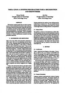
driven development approach with the emphasis on how to ensure that the implementation satisfies timing properties which has been satisfied in model. Figure 1 shows the overall process. During the requirements and design phases of the software life cycle, developers first start from formal modeling with timed automata of the real-time software. Second, model checking is performed on the timed automata model with respect to desired properties using a real-time model checker such as U PPAAL. We focus on safety properties, especially timing properties which require that a certain event should happen no later than a specific delay. Given a formal model proven correct with respect to the properties, an implementation code is synthesized in the third step. In the fourth step, we check to see if the same properties checked on the model are still satisfied by the code running on a target platform. If some timing properties are not satisfied by the code, we measure how much actual time deviates from the expected. During the fourth step, we find a timing tolerance value, ∆, through the measurement-based timing analysis. Guards in the code become relaxed with this ∆ to make timing properties satisfied by the code. Once it is confirmed that the code satisfies the desired timing properties with the ∆, changes of the code, i.e., relaxed guards with the ∆, are reflected to the model in the fifth step. If the modified model still satisfies all the properties, the overall process ends. Otherwise, the process is repeated by revising the problematic model and the code. We will describe each step with the pacemaker example in the following subsections. Software life cycle
Development process
Verification and validation process
Requirement analysis
Design
Timed automata model of pacemaker
System spec.
Implementation
synthesis
C code
compiled into
Measurement
Model checking with UPPAAL
Integration
based timing analysis
Rechecking with ∆
Figure 1. Overall process of a safety-assured development for a real-time pacemaker software
B. Formal Modeling We used the Boston Scientific’s system specification for a pacemaker [10]. Because timing constraints are so prevalent in the specification of the pacemaker, it is intuitive and straightforward to use timed automata [11] as our modeling language. Here we use the U PPAAL tool [2] to specify a timed automata model of the pacemaker in VVI mode.
is paced or sensed, current state is changed to WaitVRP WaitVRP: In this state the pacemaker does nothing but waiting for a VRP period to end. It returns to the WaitRI state after a VRP period by setting hpenable to hp and started to true. hpenable and started are auxiliary variables to be used in property description for model checking. 2) Heart Model: The second automaton, Heart, shown in Figure 2(b), simulates a human heart. It is an environment for us to simulate and verify the pacemaker software in modeling phase. There is only one state, Ready, where the heart waits a ventricular pacing event from the pacemaker or randomly sends a ventricular sensing event to the pacemaker during time interval between lower bound (minwait) and higher bound (maxwait) for two consecutive heart beats. Once it sees an event in the channel VPace or VSense in the Ready state, it goes to the Ready state again by resetting the clock. •
(a) Ventricle controller model
(b) Heart model Figure 2.
Uppaal model for a pacemaker in VVI mode
We extracted properties to be satisfied by the VVI mode pacemaker from the system specification. LRI, HRI, and VRP are considered most important timing periods which should be guaranteed by the VVI mode pacemaker. Figure 2 shows two automata for Ventricle and Heart, representing a ventricle controller of the VVI mode pacemaker and a heart model as an environment, respectively. 1) Ventricle Model: Ventricle automaton shown in Figure 2(a) captures sensing signals from the ventricle of the heart and emitting ventricular pacing signals to the heart. Three important timing periods LRI, HRI, and VRP were captured in this automaton. The constants for timing intervals can be various from patients to patients. Normal values of these constants are 1000ms for LRI, 1200ms for HRI, and 320ms for VRP. Event channels are used to communicate between different components of the system. The primary channels are VPace and VSense representing channels for paces and senses in the ventricle, respectively. There are two states WaitRI and WaitVRP in the Ventricle timed automaton in Figure 2(a). • WaitRI: The pacemaker starts from this state and waits for a ventricular sensing or pacing event. If sensing does not occur before RI period ends, the ventricle controller sends a pacing signal to the heart and the timer x is reset. RI value turns into LRI and hp is set to false. hp is a boolean value for setting hysteresis pacing. When the hysteresis pacing is applied (i.e., hp is true), the pacemaker provides a longer period (i.e., HRI) following a sensing event before pacing. hp is set to true after every ventricular sensing or false after every ventricular pacing. It determines whether LRI and HRI will be assigned to RI. For Transition 2, when a ventricular sense occurs, the timer x is reset, HRI is assigned to RI and hp is set to true. Once the ventricle
C. Formal Verification We mapped the timing requirements to corresponding verification queries in U PPAAL. For easy reference to the properties, we labeled a unique name to each property. These are four properties which we used in verification: • PropDeadlock: Deadlock freeness A[] (not deadlock) This property is checked to make sure that there are no deadlocks in any execution sequences. • PropLRI: Lower Rate Limit under disabled Hysteresis Pacing A[] (!Ventricle.hpenable imply Ventricle.x = RI. It means that the implementation will be able to check the
guard of the respective transition 2ms earlier; thus, making a pacing event no later than RI becomes possible, resulting in satisfying the corresponding timing property. Note that we did not change the guard of Transition 4 because the PropVRP was never violated. Only transitions relevant to the violated PropLRI and PropHRI were changed. Table II is the result of enforcing 2ms timing tolerance in the program. We can now see that all of three timing properties are satisfied with the modified guards with the timing tolerance. Last but not the least, to validate the # 1 2 3 4 5 6
Heart Event (ms) P:998.880 P:998.720 S:793.760 S:1000.704 P:1198.204 P:998.496
VRP – – Yes Yes – –
LRI Yes Yes – – – Yes
HRI – – – – Yes –
semaphore for the location from which the corresponding transition starts. It then will check the guard by reading the clock value, waiting for input event signal semaphores, if any, and evaluating Boolean guards. If the guard is false, the thread will repeat the above logic. If the guard is true, it will execute the associated actions, including updating shared variables, resetting clocks, posting semaphores for output signals, and switching locations (changing a process variable cur_loc indicating the current location of the automaton, as well as posting respective semaphores). This scheme can be described with pseudo-code in Listing 2.1 With this scheme, we can systematically generate code (though currently manually) for the multi-threaded approach. 1
3 4 5
Table II
6
R ECHECKING RESULT OF SINGLE - THREADED CODE
7 8 9
changes in the code, we also propagate changes backward to the models. With the timing tolerance value ∆, we verified all the properties on the modified model again. The result showed that all the properties were still satisfied. This result confirmed that the change of the code does not harm preservation of all the desired timing properties. B. Multi-threaded Approach There are at least two schemes to employ multiple threads to synthesize code for timed automata models. One is to implement the behavior of each timed automaton in one thread, and communications between channels of these timed automata are implemented using thread communications provided by the underlying operating system running on the board. In another approach, inspired by the generated code from E LASTIC 2B RICK tool [4], the transition functions run in individual threads and are triggered by events sent to the respective threads. 1) Code Generation: The E LASTIC 2B RICK tool can produce C code for L EGO M INDSTORMSTM running B RICKOS from timed automata models without invariants. Since it does not support shared variables and we are targeting PIC18 MCU platform [12], we did not use E LASTIC 2B RICK directly but implemented our U PPAAL models in a manual but systematic scheme similar to the structure of the code automatically generated by the E LASTIC 2B RICK tool. With thread support in PIC18 MCU’s operating system PICos18 [13], our approach implements shared variables as process variables, which can be accessed by all threads in the hosting process. In our code generation scheme, each transition of an automaton is transformed into a single thread. The structure for such a thread is as follows. The thread will wait for the
task Template
2
10 11 12 13 14 15 16 17 18
while true WaitEvent(CURR_LOC_EVENT); ClearEvent(CURR_LOC_EVENT); thread specific calculation sleep when necessary if ((sleeping is used) and (cur_loc is changed when waking up)) cancel transition else update variables clear timer when necessary change to destination location SetEvent(DEST_task_ID, EVENT_ID); perform verification end if end while Listing 2.
Task Template
The variable cur_loc is used to check if the automaton is still at the same location when it wakes up from sleeping (corresponding to waiting for a certain period in the model). For example, in the ventricle controller model in Figure 2(a), Transition 2 and Transition 3 may both happen when the automaton is in the state WaitRI. The thread for Transition 2, however, will sleep for the duration of RI because of the guard condition x >= RI. In the meanwhile, Transition 3 may happen without such constraint and the corresponding thread can change the value of cur_loc to WaitVRP. When the thread for Transition 2 wakes up, checking for cur_loc fails and Transition 2 is not taken in effect. 2) Checking Timing Constraints: Testing scenarios: As in the single threaded approach, we used the test scenarios of Pacing–Pacing, Pacing– Sensing, and Sending–Pacing and checked whether the properties PropLRI, PropHRI, and PropVRP hold in the code. Checking method and result: Note that in the template in Listing 2, we also instrumented the perform verification which does the same checking as in the single-threaded approach. One difference, however, is that, 1 On the PICos18 OS we are using, threads and semaphores are actually simplified to tasks and events, respectively.
to avoid printing overhead in the multi-threaded approach,2 we pre-allocated memory locations to arrays for recording timing information. Printing of the functions is finished later when monitoring is stopped. In doing so, we can bring the time spent on monitoring to the minimum amount. To measure the execution time of one iteration of a thread (corresponding to the execution time for one transition), we record the time immediately after the thread has been waken up, and when an execution of one iteration finishes, another time value is recorded. We tested the program with the test scenarios several times, but repetitive execution did not make much differences because the experiment was conducted in the simulator environment and random numbers used to simulate heart beats were predefined ones. Experiment synthesized from one nominal sample run of this approach is shown in Table III. We observe from the result that the PropVRP property holds for all the values, while the PropHRI and PropLRI properties do not hold. # 1 2 3 4 5 6 7 8 9 10 11 12
Heart Event (ms) P:1001 S:395 P:1202 S:687 S:1089 P:1202 S:419 S:1184 P:1202 S:642 P:1202 P:1001
VRP – Yes – Yes Yes – Yes Yes – Yes – –
LRI No – – – – – – – – – – No
HRI – – No – – No – – No – No –
Table III C HECKING RESULT OF MULTI - THREADED CODE
Re-checking result: We modified our multi-threaded code to incorporate the result of our experiment, using 2ms as the timing tolerance value ∆, and experimented again. The result is shown in Table IV. # 1 2 3 4 5 6 7 8 9 11 12
Heart Event (ms) S:872 P:1200 S:398 S:1153 S:351 P:1200 P:1000 S:444 P:1200 P:1000 P:999
VRP Yes – Yes Yes Yes – – Yes – – –
LRI – – – – – – Yes – – Yes Yes
HRI – Yes – – – Yes – – Yes – –
Table IV R ECHECKING RESULT OF MULTI - THREADED CODE
It can be observed from the result that the PropLRI and PropHRI properties now hold. As is with the single-threaded approach, we modified the model according to the changes to the code and verified the properties again. All the properties were still satisfied by the modified model. In the worst case, it may be possible that such a timing tolerance value of ∆ cannot be found. For example, the smallest timing tolerance value of ∆ may be larger than the allowed tolerance value from specifications. If this happens, the implementation of the code should be examined to see if the underlying coding scheme is sufficient enough for achieving timing constraints. V. D ISCUSSION A. Type of Timing Properties
Timing analysis: According to the above experiment result, we can see that there is always a delay than expected pacing time. The maximum delay is bounded in the above result by 2 milliseconds. One observation is that, making an event happen at the exact expected time is not possible, since there is always a processing delay between the time an event is supposed to happen and the time that it is actually carried out. This deviant is unavoidable for any implementations on any real platforms we use. However, another observation from our experiment result is that, the deviant values can be bounded. If we incorporate this bound to the code and make the events happen earlier, it is possible to reduce the violations of the desired timing properties. For example, with the knowledge that all time delays are within 2ms, we can modify our code such that the events happen 2ms earlier than expected. This is the idea for the “re-checking” step. 2 Due to limitations of the PICos18 OS, the minimum time resolution obtainable from the program is 1ms.
From the experiment of property checking in the code, we found that verification results are highly dependent on types of timing properties. We dealt with following types of timing properties: 1) whenever a certain event happens, a timer value should be greater than or equal to a certain value, and 2) whenever a certain event happens, a timer value should be less than or equal to a certain value. Properties requiring that a specific timer be always greater than or equal to a certain time limit when an event happens (e.g., VRP period check) were always satisfied on the code. We did not put any changes to the code in these satisfied cases. Properties requiring that a specific timer be always less than or equal to a certain time limit when an event happens (e.g., LRI and HRI period checks) were not satisfied in many cases. To make sure a desired event occur no later than the specified time instant, we made guard-checking done earlier by considering execution time of corresponding code segments. We considered two types of timing properties in our approach. More complex types of timing properties need to be considered in future work.
B. Instrumentation Overhead Checking properties on the code often requires additional instrumentation code such as code for evaluating checking condition and printing. Time overhead from instrumentation code may sometimes cause the code to fail in satisfying timing properties. In our pacemaker example, time for the instrumentation code did not affect the code in its satisfaction of three major timing properties although time delay which we measured includes overhead time for the instrumentation code. However, this example does not cover general cases. Although instrumentation overhead is considered ignorable as far as it does not harm timing property preservation in our approach, reducing instrumentation overhead is strongly preferable. Extensive work has been done in code instrumentation and improving the performance and accuracy of time profilers based on code instrumentation. Existing techniques can be applied to our approach to make the ∆ safely tighter. C. Code Generation Scheme We showed two different code generation schemes from timed automata and demonstrated how the proposed approach can be applied to them. Different code structure can make different impacts on timing properties. Although significant differences between two code schemes in terms of timing tolerance, performance, property preservation, etc. were not found in our case study, we witnessed that the multi-threaded code scheme has more time uncertainty than the single thread. We have a plan to analyze and evaluate different code generation schemes from timed automata. D. Scalability The proposed approach includes both manual and automatic operations. Scalability issue may be raised when the proposed approach is applied to development of complex real-time software. The proposed development approach would be much more useful if it is supported by automated tools. There are many spaces where automated tools can be used to improve the applicability of this approach to large real-time software. Creating a formal model from system specification is generally done manually. Model checking on the created model is performed automatically. For the code synthesis, use of automated tools for code synthesis is highly recommended. However, it is not always easy to find tools fit for the developer’s purpose because code synthesis for models is inherently model-dependent and platform-dependent. If it is the case, automatic code generation using an existing tool complemented by manual modification or development of a new tool can be considered. We utilized T IMES and E LASTIC 2B RICK tools to generate the basis codes from the timed automata model and modified the generated codes manually to make them executable in a different hardware platform in our case study.
Alterations to the model based on code changes have been made manually in the proposed approach. However, it is highly possible to automate this alteration process by implementing backward mapping from the generated code to the formal model because mapping changes in the code to changes in the model may not be difficult as far as the code generation process is systematic. E. Generalization The proposed development approach can be applied to development of general safety-critical real-time software with different design decisions, although we showed a few specific decisions in our case study - timed automata as a modeling language, U PPAAL as a verification tool, stop watch technique as a timing analysis method, and two specific methods of code synthesis. As long as the modeling language captures timing behaviors of the system and the formal verification tool can check safety timing properties, other modeling languages and verification tools may also be used. As long as the code synthesis is systematic and sound, other synthesis techniques can also be used. Moreover, as long as the timing analysis method can give information to find ∆, other timing analysis methods can be used in the proposed development approach. VI. R ELATED W ORK A. Code Generation from Timed Automata Code generation from state machines in general is a well studied topic [15]. Specifically, a couple of tools support generating code from timed automata [11]. The T IMES tool [14] is designed for modeling and implementation of embedded systems. Main targets are time/event triggered systems which can be described as sets of tasks. It supports code generation from timed automata extended with tasks for B RICKOS [6] platform. Assuming synchrony hypothesis, the code synthesis of the T IMES is guaranteed to preserve safety, schedulability and boundedness properties given those properties have been checked on a system design model prior to its implementation. The E LASTIC 2B RICK [16] tool is based on the AASAP semantics [4]. It takes a simplified version of timed automata without invariants as its specification language and generates code for B RICKOS platform. The E LASTIC 2B RICK approach guarantees that safety properties proven correct with ∆ in the model are preserved in the generated code, when certain assumptions for the execution time and the clock precision are satisfied. Neither shared variables among different automata nor broadcasting communications are supported by the E LASTIC 2B RICK tool. B. Timing Analysis on C code Worst Case Execution Time (WCET) analysis is one of the commonly used timing analysis techniques. WCET analysis techniques are categorized into dynamic and static analysis.
Dynamic timing analysis is based on measuring exhaustive running on program code including profiling, emulating, and logic analysis. pWCET [17], a dynamic WCET analysis tool, computes probabilistic execution time bounds. Static timing analysis is based on analyzing mathematical model on program code without running program code. Since static timing analysis rely on mathematical model, it is more accurate than testing-based dynamic timing analysis. Some of commercial WCET tools using static timing analysis techniques are RapiTime [18], Bound-T [19], and aiT [20]. [18] and [20] support WCET analysis for restricted subsets of ANSI C. Currently, we are using a rather simple technique to obtain execution time of the code in the proposed approach. We have a plan to use existing WCET analysis techniques and tools to find more rigorous timing tolerances. VII. C ONCLUSION We presented a safety-assured development method of a real-time software. While following model-driven development concept basically, we modeled the real-time system with timed automata and performed model checking on it. After generating implementation code systematically from timed automata model, we checked preservation of properties transferred from model on the implementation code. When a timing property was violated on the code, we tried to find a timing tolerance ∆, which can be used to make the property satisfied by enlarging the corresponding guard in the code. This ∆ was obtained based on measuring time deviation from the expected one. In order to confirm that this ∆ can be safely used, model checking with respect to all the properties was performed again on the modified model having corresponding changes. We used a pacemaker software as our case study to demonstrate how this approach can be applied to development of real-time software. Theoretical analysis of the proposed approach and comparison of different code generation schemes are in progress. We also have a plan to construct assurance cases for our pacemaker software to figure out how the proposed methodology can affect construction of assurance cases.
[3] T. Amnell, E. Fersman, P. Pettersson, W. Yi, and H. Sun, “Code synthesis for timed automata,” Nordic J. of Computing, vol. 9, no. 4, pp. 269–300, 2002. [4] M. de Wulf, L. Doyen, and J.-F. Raskin, “Systematic implementation of real-time models,” in FM, ser. Lecture Notes in Computer Science, J. Fitzgerald, I. J. Hayes, and A. Tarlecki, Eds., vol. 3582. Springer, 2005, pp. 139–156. [5] K. Altisen and S. Tripakis, “Implementation of timed automata: an issue of semantics or modeling,” in In Proc. 3rd Int. Conf. Formal Modelling and Analysis of Timed Systems (FORMATS05), Lecture Notes in Computer Science. Springer, 2005, pp. 273–288. [6] S. Nielsson, “Introduction to the legOS kernel,” Sep. 2000. [7] M. D. Wulf, L. Doyen, and J. francois Raskin, “Almost ASAP semantics: From timed models to timed implementations.” Springer, 2003, pp. 296–310. [8] Oregon Health and Science University, “Overview of pacemakers,” http://www.ohsu.edu/health/index.cfm. [9] S. S. Barold, R. X. Stroobandt, and A. F. Sinnaeve, Cardiac Pacemakers Step by Step: An Illustrated Guide. Blackwell Futura, 2005. [10] Boston Scientific, “Pacemaker system specification,” Jan 2007, http://sqrl.mcmaster.ca/ SQRLDocuments/ PACEMAKER.pdf. [11] R. Alur and D. L. Dill, “A theory of timed automata,” Theoretical Computer Science, vol. 126, pp. 183–235, 1994. [12] Microchip, “PIC18 family microcontroller,” http://www. microchip.com/. [13] Pragmatec Inc, “PICos18 : RTOS for PIC18,” http://www. picos18.com/. [14] Uppsala University Design and Analysis of Real-Time Systems team, “TIMES–a tool for modeling and implementation of embedded systems,” 2007, http://www.timestool.com. [15] M. Samek, Practical UML Statecharts in C/C++, Second Edition: Event-Driven Programming for Embedded Systems, 2nd ed. Elsevier, Oct. 2008.
ACKNOWLEDGMENT
[16] M. D. Wulf, “From timed models to timed implementations,” Ph.D. dissertation, Universit´e Libre De Bruxelles, 2007.
This research was supported in part by NSF CNS0931239, NSF CNS-0930647, NSF CNS-0834524, and NSF CNS-0720703.
[17] NEXT TTA, “pwect: Probabilistic worst case execution time analysis,” http://www.pwcet.com/.
R EFERENCES [1] Software Quality Research Laboratory, “Pacemaker formal methods challenge,” http://sqrl.mcmaster.ca/pacemaker.htm. [2] G. Behrmann, A. David, and K. G. Larsen, A Tutorial on Uppaal, Department of Computer Science, Aalborg University, Denmark, Nov 2004.
[18] Rapita Systems Ltd., “Rapitime on target timing analysis,” http://www.rapitasystems.com/rapitime. [19] Tidorum Ltd., “Bound-T time and stack analyser,” http:// www.pwcet.com/. [20] AbsInt., “aiT worst-case execution time analyzers,” http: //www.pwcet.com/.