solve dense linear algebra problems, we design a class of heterogeneous ... of
high performance parallel linear algebra libraries have been developed so far.
CONCURRENCY AND COMPUTATION: PRACTICE AND EXPERIENCE Concurrency Computat.: Pract. Exper. 2014; 00:2–35 Published online in Wiley InterScience (www.interscience.wiley.com). DOI: 10.1002/cpe
A Scalable Approach to Solving Dense Linear Algebra Problems on Hybrid CPU-GPU Systems Fengguang Song1∗ , Jack Dongarra2,3,4 1 Indiana
University–Purdue University Indianapolis, 2 University of Tennessee, 3 Oak Ridge National Laboratory, 4 University
of Manchester
SUMMARY Aiming to fully exploit the computing power of all CPUs and all GPUs on hybrid CPU-GPU systems to solve dense linear algebra problems, we design a class of heterogeneous tile algorithms to maximize the degree of parallelism, to minimize the communication volume, as well as to accommodate the heterogeneity between CPUs and GPUs. The new heterogeneous tile algorithms are executed upon our decentralized dynamic scheduling runtime system, which schedules a task graph dynamically and transfers data between compute nodes automatically. The runtime system uses a new distributed task-assignment protocol to solve data dependencies between tasks without any coordination between processing units. By overlapping computation and communication through dynamic scheduling, we are able to attain scalable performance for the double-precision Cholesky factorization and QR factorization. Our approach demonstrates performance better than both vendor (e.g., Intel MKL) and open source libraries (e.g., StarPU, PLASMA) in the following four possible environments: heterogeneous clusters with GPUs, conventional clusters without GPUs, sharedsystems with multiple GPUs, and shared-memory multicore computers. c 2014 John Wiley & Sons, Ltd. Copyright Received . . .
KEY WORDS: Dense linear algebra, heterogeneous HPC systems, distributed dataflow scheduling, runtime systems. c 2014 John Wiley & Sons, Ltd. Copyright Prepared using cpeauth.cls [Version: 2010/05/13 v3.00]
2
F. SONG AND J. DONGARRA
1. INTRODUCTION
Over the last few years, on GPUs, the computational performance, energy efficiency, and ease of programming, as well as cost per flops, have improved steadily [1, 2, 3, 4]. It thus becomes appealing and more common to attach multiple GPUs to a multicore host system to deliver the highest performance possible. According to the November 2013 Green500 list [5], all of the top ten “greenest” systems are heterogeneous accelerator-based systems. However, there is little software that can take advantage of large-scale heterogeneous systems efficiently, especially for utilizing all CPU cores and all GPUs. Similar to the impact of multicore on new software design [6, 7, 8, 9], we have to rethink our software design for the heterogeneous multicore and multi-GPU architectures. Since many common operations in scientific computing are carried out through linear algebra libraries, we target at providing the fundamental linear algebra operations on the new heterogeneous systems. A number of high performance parallel linear algebra libraries have been developed so far. For instance, LAPACK[10], Intel MKL, AMD ACML, and PLASMA[11] are mainly designed for sharedmemory multicore machines. ScaLAPACK [12] and TBLAS[13, 14] are designed for distributedmemory CPU-based machines. CUBLAS[15], CULA[16], and MAGMA[17] provide a subset of the subroutines of LAPACK for GPUs. The current releases of these libraries, however, do not support distributed-memory multicore and multi-GPU clusters. In this paper, we attempt to take into account a combination of nice properties — “heterogeneity-friendly”, “multicore-friendly”, communication-reducing, and synchronizationreducing—to achieve the maximum performance possible. Our goal is to provide a unified framework to solve linear algebra problems on any number of CPU cores, any number of GPUs, and on either shared- or distributed-memory systems. We design heterogeneous algorithms with hybridsize tasks to accommodate the processor heterogeneity. The heterogeneous algorithms are based ∗ Correspondence
to: Department of Computer Science, Indiana University–Purdue University Indianapolis, Indiana
46202, USA. Email:
[email protected] c 2014 John Wiley & Sons, Ltd. Copyright Prepared using cpeauth.cls
Concurrency Computat.: Pract. Exper. (2014) DOI: 10.1002/cpe
A SCALABLE APPROACH TO SOLVING DENSE LINEAR ALGEBRA ON HYBRID CPU-GPU SYSTEMS
3
on a block data layout, and can generate fine-grain tasks and exhibit a high degree of parallelism such that no CPU core or GPU becomes idle. To minimize communication, we introduce a static scheme to distribute data across different host systems and GPUs on a cluster. The essentially datacentric computing is able to reduce many unnecessary data transfers. Within each host or GPU, we use a dynamic scheduling method to schedule tasks to reduce synchronizations and to overlap computation and communication greatly. Our solution mainly consists of four components: (1) a simple heterogeneity-aware data distribution method, (2) a class of heterogeneous tile algorithms, (3) a decentralized dynamic scheduling runtime system, and (4) a distributed task assignment protocol. It works as follows. Given a matrix input, we first split it into tiles of different sizes. Then we distribute the tiles to the host-system memories and GPU device memories on a cluster using a multi-level distribution method. Each compute node executes a runtime system (launched as an MPI process) that schedules tasks within the node dynamically. Different nodes communicate with each other through MPI messages, and within each node, a runtime system launches a number of threads to control the node’s CPU cores and GPUs. Our runtime system follows the data-flow programming model and builds then executes a partial directed acyclic graph (DAG) dynamically. The class of heterogeneous tile algorithms are designed to take advantage of the architectural strengths from both CPUs and GPUs. That is, GPUs are optimized for throughput and require much larger input size than CPUs to obtain high performance [1]. We modify and extend tile algorithms [8] to heterogeneous tile algorithms so that during an execution, there are a great number of small tasks for CPU cores, and a great number of large tasks for GPUs, to compute concurrently at any time. A heterogeneous tile algorithm is based upon two types of tasks: small tasks for CPU cores, and large tasks for GPUs. The core component in our approach is the distributed dynamic scheduling runtime system. Every compute node is executing a runtime system that can solve data dependencies dynamically, and send data from a parent task to its children transparently. The runtime system on each node consists of seven subcomponents: (1) a fix-size task queue to store generated tasks, (2) ready task queues, (3)
c 2014 John Wiley & Sons, Ltd. Copyright Prepared using cpeauth.cls
Concurrency Computat.: Pract. Exper. (2014) DOI: 10.1002/cpe
4
F. SONG AND J. DONGARRA
a task-generation thread to execute a sequential program and generate new tasks, (4) a set of CPU computation threads (one per CPU core), (5) a set of GPU management threads (one per GPU), (6) a CUDA communication thread to transfer data among the host and GPUs within a node, and (7) an MPI communication thread to transfer data between different nodes. Moreover, the core technology used in the distributed runtime system is a distributed task assignment protocol. All runtime systems (one runtime per node) will execute the distributed taskassignment protocol to build subsets of a DAG dynamically. The protocol guarantees that there is no communication or coordination required when building the DAG. It also guarantees that all runtime systems make a unanimous decision without coordinating with each other such that every task is computed by one and only one computing unit (on a host or GPU). Every input and output of a task is represented by an instance of the task, where an input task instance denotes a “consumer”, and an output instance denotes a “producer”. A runtime system inspects every new task on behalf of the runtime’s resident node. If an input of the task is allocated to the node, the runtime system will create an input instance, while the other runtime systems will ignore the input instance. Based on the protocol, an input or output task instance is always assigned to the computing unit where the input or output data is actually stored. Our experiments with Cholesky and QR factorizations, on the heterogeneous Keeneland system [18] at the Oak Ridge National Laboratory, show great scalability on 100 nodes using all CPUs and GPUs. We also apply our framework to the other three possible environments: clusters without GPUs, a shared system with both CPUs and GPUs, and a shared-memory system only with CPUs. Compared with vendor-optimized (e.g., Intel MKL) and open source libraries (e.g., PLASMA, StarPU), our framework is able to provide better performance in the first two environments, that is, clusters without GPUs (66% better with 100 nodes), and shared-system multiGPUs (up to 250% better). Even in the smallest-scale environment (i.e., a shared-memory system with multicore CPUs only), we can still attain a high performance comparable to the vendor-optimized libraries. In addition, we attain scalable performance of 21 TFlops on an Nvidia Kepler GPU cluster using 32 nodes, each with sixteen AMD Opteron cores and a single Nvidia Kepler K20 GPU.
c 2014 John Wiley & Sons, Ltd. Copyright Prepared using cpeauth.cls
Concurrency Computat.: Pract. Exper. (2014) DOI: 10.1002/cpe
A SCALABLE APPROACH TO SOLVING DENSE LINEAR ALGEBRA ON HYBRID CPU-GPU SYSTEMS
5
2. MOTIVATIONS FOR SOME DESIGN CHOICES
On a CPU-based host that is attached with multiple GPUs via PCI-Express connections, the performance ratio of computation to communication on GPUs keeps increasing. Eventually the communication time on the PCI-Express connection will become the bottleneck of the entire system. As proved by Kung [19], if the
compute communicate
ratio rises by α, the device memory on a GPU must
increase by α2 in order to keep the system balanced for matrix computations (a system is “balanced” if the computation time is equal to the IO time on the system). Hence, we place greater emphasis on minimizing communication overhead in our design. On the other hand, since GPUs are optimized for throughput[1], GPUs expect a larger task size than CPUs to attain high performance. We perform experiments with concurrent GPU kernels to test whether we can decrease the task size on GPUs.
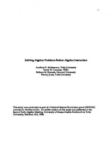
2.1. Reasons to Use a Static Data Distribution We first attempted to implement a dynamic scheduling runtime system, where all the CPU cores and GPUs share a global ready task queue, and each GPU owns a software cache on its device memory. All the data in the GPUs’ software caches are backed up by the main memory on the host. Whenever a GPU reads a block of data from the host, it stores the data to its software cache. We have used two cache writing policies: write-through and write-back. To achieve the best performance, our software cache size is configured as large as the input matrix size to eliminate the capacity cache misses (now only compulsory and coherence misses are left). Figure 1 shows our experiments with Cholesky factorization (in double precision) on a single node of the Keeneland system using twelve CPU cores and three Nvidia Fermi GPUs. In the figure, we compare our attempted software-cache dynamic runtime system, the general-purpose dynamic scheduling system of StarPU [20], and our new GPU framework (we refer to it as Distributed-GPUs framework) based on a static data distribution. By changing from the write-through policy to the write-back policy, we can improve the program performance greatly because of the reduced communication. StarPU consists of profiling, performance modeling, and different scheduling policies to achieve load balancing and reduce data transfers. However, since our c 2014 John Wiley & Sons, Ltd. Copyright Prepared using cpeauth.cls
Concurrency Computat.: Pract. Exper. (2014) DOI: 10.1002/cpe
6
F. SONG AND J. DONGARRA
static data distribution method can guarantee a near lower-bound communication cost and has less runtime overhead, it is faster than StarPU by up to 250% for small to relatively large matrix sizes. This inspired us to use a static data distribution strategy. Here we emphasize that our framework is more domain specific (in particular for matrix problems), while StarPU is more generic and can support various domains. Distri-GPUs framework Write-back cache Write-through cache StarPU 0.9.1
1920 3840 5760 7680 9600 11520 13440 15360 17280 19200 21120
Gflops
800 700 600 500 400 300 200 100 0
Maxtrix Size
Figure 1. A comparison between various dynamic scheduling runtime systems and our distributed-GPU framework, which is based on a static data distribution method.
2.2. Reasons to Create Large Tasks on GPUs There are two possible ways to obtain maximum performance on GPUs: sending a sufficiently large task to GPU, or sending many small-size tasks to GPU and compute them concurrently on different streaming multi-processors. Also, there are three ways to design algorithms to utilize both CPUs and GPUs: (i) algorithms that generate tasks of uniform size that is large and suitable for GPUs (e.g., N > 1000), (ii) algorithms that generate tasks of uniform size that is small and suitable for CPU cores (e.g., N = 200), or (iii) algorithms that generate two types of tasks: small tasks suitable for CPU cores and large tasks suitable for GPUs. We did not use the first option because feeding a matrix of size N > 1000 to a single CPU core is much slower than dividing it into submatrices and computing them in parallel by multiple cores. One could use several CPUs to solve large tasks in a fork-join manner, but it will induce additional synchronization overhead and more CPU idle time [7, 8, 9]. c 2014 John Wiley & Sons, Ltd. Copyright Prepared using cpeauth.cls
Concurrency Computat.: Pract. Exper. (2014) DOI: 10.1002/cpe
A SCALABLE APPROACH TO SOLVING DENSE LINEAR ALGEBRA ON HYBRID CPU-GPU SYSTEMS
7
350
Gflops
300
350 300 250 200 150 100 50 0
250 200 150 100 50 0
0 200 400 600
Kernel
800
input s100012001400 1800 ize (N) 1600 2000 0
2
8
10
nt
6 e urr nc o C
4
12
14
16
els
rn ke
#
Figure 2. Concurrent kernel execution of double-precision matrix multiplications on an Nvidia Fermi GPU.
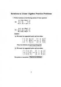
With the technique of concurrent GPU kernel execution, it seems feasible to design algorithms that only have small tasks. A host program can create GPU streams to launch many small tasks on a GPU and compute them in parallel. However, the performance of concurrent kernel execution is not as good as the performance of computing a large task. Figure 2 shows our experiment with concurrent kernel execution for matrix multiplications (i.e., cublasDgemm) on an Nvidia Fermi GPU. As shown in Fig. 2, for every kernel input size, we launch k concurrent matrix multiplication kernels (1 ≤ k ≤ 16) on the GPU and measure the execution time to complete all the k kernels. From the experiment, we can make the following observations:
• The concurrent kernel execution may improve performance significantly only when N is
small. For instance, when N=64, the speed up is 16 by using 16 concurrent kernels. However, the speedup decreases to twice when N=320. When N ≥ 960, the maximum speed up is merely 10%. • If N ≤ 512, the best performance is just 235 Gflops no matter how many concurrent kernels
are used. • When N ≥ 1088, even with a concurrency level of 1, the Nvidia Fermi GPU achieves 95% of
the maximum performance (i.e., 302 Gflops).
Considering the fact that a single large task can deliver 22% higher performance than a number of concurrent small tasks, we choose the third option which generates small and large tasks for CPUs and GPUs, respectively. c 2014 John Wiley & Sons, Ltd. Copyright Prepared using cpeauth.cls
Concurrency Computat.: Pract. Exper. (2014) DOI: 10.1002/cpe
8
F. SONG AND J. DONGARRA
3. HETEROGENEOUS TILE ALGORITHMS
Our previous work has designed and applied heterogeneous tile algorithms to shared-memory systems [21]. Here we use Cholesky factorization as an example to describe the algorithms briefly.
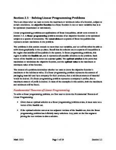
3.1. An Example of Heterogeneous Tile Cholesky Factorization As shown in Figure 3, we factorize a matrix of 3 × 3 top-level large tiles, each of which is divided into one small and one large rectangular tiles. The factorization goes through six iterations, where the k -th iteration works on a trailing submatrix that starts from the k -th tile column. Since all iterations apply the same operations to A’s trailing submatrices recursively, the figure just shows the operations of the first iteration. We also list the computational kernels used in Figure 3 as follows: tk1 • POTF2’(Atk , Ltk ): Given a matrix Atk of m × n and m ≥ n, we let Atk = ( A Atk2 ) such that tk1 Atk1 is of n × n, and Atk2 is of (m − n) × n. We also let Ltk = ( L Ltk2 ). POTF2’ computes
−T tk1 (L Ltk2 ) by solving Ltk1 = Cholesky(Atk1 ) and Ltk2 = Atk2 Ltk1 .
• TRSM(Ltk , Aik , Lik ) computes Lik = Aik L−T tk . • GSMM(Lik , Ljk , Aij ) computes Aij = Aij − Lik LTjk .
1
2
3
4
5
6
1
2
3
4
5
6
1
1
1
2
2
2
3
2
3
4
2
3
1
2
3
(b) 5
1
6
2
3
4
6
1
1
2
2
2
6
4
5
6
3
3
(d)
5
(c) 5
1
3
4
3
3
(a) 1
1
(e)
(f )
Figure 3. The operations of heterogeneous tile Cholesky factorization: (a) Symmetric positive definite matrix A; (b) compute POTF2’ to solve L11 ; (c) apply L11 to update its right A12 by GSMM; (d) compute TRSMs
for the tiles below L11 ; (e) apply GSMMs to update all tiles on the right of the first tile column; (f) At the second iteration, repeat (b), (c), (d), (e) on the trailing submatrix that starts from the second tile column. c 2014 John Wiley & Sons, Ltd. Copyright Prepared using cpeauth.cls
Concurrency Computat.: Pract. Exper. (2014) DOI: 10.1002/cpe
A SCALABLE APPROACH TO SOLVING DENSE LINEAR ALGEBRA ON HYBRID CPU-GPU SYSTEMS
9
3.2. A Simple Multi-level Block Cyclic Data Distribution (BCDD) We design a simple multi-level partitioning scheme to create small and large tiles to work with the previous heterogeneous tile algorithms. The distribution scheme works as follows: 1. At the top level, we divide a matrix into a set of p × p large square tiles of size B × B . 2. At the middle level, we distribute the p × p large tiles to a process grid with Pr rows and Pc columns using a 2-D block cyclic method, where each node has a single process. 3. At the bottom level (i.e., within each node), we vertically cut every tile of size B × B on the local node into a number of s small tiles of size B × b, and a remaining large tile of size B × (B − s · b). We always allocate the small tiles to all CPUs on the host, meanwhile allocate the remaining tiles to GPUs using a 1-D or 2-D block cyclic method. So far we use a 1-D method because of the small number of GPUs (e.g., at most 4) on each compute node. Figure 4 illustrates how to use the simple multilevel 2-D block cyclic method to distribute a matrix of 6 × 6 large square tiles to a 2 × 2 process grid (i.e., P1 , P2 , P3 , P4 ). Suppose each process runs on a compute node with three GPUs installed (i.e., G1, G2, G3). First, the 6 × 6 large tiles are allocated to four processes so that each process has 3 × 3 local large tiles (e.g., P1 has 3 × 3 local tiles as shown on the right hand side of the figure). Second, each process assigns its 3 × 3 local large tiles to its three GPUs using a 1-D column-wise distribution. Third, again on each process, we cut an appropriate slice from every GPU tile and assign it to the host. In our implementation of the Cholesky and QR factorizations, we use an auto-tuning method to determine the size of the slice based on the performance of computational kernels on CPU cores and GPUs. P1
P2
P1
P2
P1
P2
P3
P4
P3
P4
P3
P4
P1
P2
P1
P2
P1
P2
P3
P4
P3
P4
P3
P4
P1
P2
P1
P2
P1
P2
P3
P4
P3
P4
P3
P4
h G1 h G2
h G3
P1
P1
P1
P1
P1
P1
P1
P1
P1
2-D BCDD
Figure 4. A simple multi-level 2-D block cyclic data distribution.
c 2014 John Wiley & Sons, Ltd. Copyright Prepared using cpeauth.cls
Concurrency Computat.: Pract. Exper. (2014) DOI: 10.1002/cpe
10
F. SONG AND J. DONGARRA
4. BASIC IDEA OF OUR DISTRIBUTED RUNTIME SYSTEM
Given a cluster with P nodes, we launch a number of P MPI processes (one process per node), each of which executes an instance of the runtime system. We assume an input matrix is stored in a hybrid tile data layout that uses two different tile sizes. The tiles are distributed to the host and GPUs across different compute nodes using the simple multi-level block cyclic data distribution method. Not only do we distribute data to hosts and GPUs on different nodes statically, but also we distribute tasks to hosts and GPUs statically. We require that the location of a task be the same as the location of the task’s output. Our task allocation is static, but we schedule tasks dynamically within a host or GPU in order to reduce synchronization points and to overlap computation with communication. Our runtime system follows the dataflow programming model and is essentially data-availability driven. When a parent task completes, it triggers its child tasks immediately. The runtime system is able to identify data dependencies between tasks and unroll a Directed Acyclic Graph (DAG) dynamically. Note that a DAG has never been created and stored explicitly in our runtime system. A parallel program starts with an entry task and finishes with an exit task of the DAG, respectively. Each runtime system instance is multi-threaded. It creates five types of threads: a task-generation thread, a set of CPU compute threads for CPU cores, a set of GPU management threads for GPUs, an inter-node MPI communication thread, and an intra-node CUDA communication thread. The task-generation thread create tasks (similar to issuing instructions) and drives the execution of a parallel program. All the task-generation threads on all compute nodes execute the same sequential code independently and create task instances for the program without any communication. They also execute a distributed task-assignment protocol. Based on the common knowledge of the static multi-level distribution, it can decide by itself which task it should compute and where the task’s children are located. Since a task’s input and output may belong to different nodes, the protocol also guarantees that a certain node generates the input instance, and another node generates the output instance in a coordinated manner. The runtime system later links the input and output task instances
c 2014 John Wiley & Sons, Ltd. Copyright Prepared using cpeauth.cls
Concurrency Computat.: Pract. Exper. (2014) DOI: 10.1002/cpe
A SCALABLE APPROACH TO SOLVING DENSE LINEAR ALGEBRA ON HYBRID CPU-GPU SYSTEMS 11
together such that the completion of a parent task triggers its child tasks (Section 6 will introduce the protocol in details).
5. THE IMPLEMENTATION
This section introduces the implementation of the compact runtime system. As shown in Fig. 5, the runtime system consists of seven components:
• Task window: a fixed-size task queue that stores all the generated but unfinished tasks. • Ready task queues: lists of ready tasks. • Task-generation thread: a single thread that executes a serial program, and generates new
tasks. • CPU compute threads: there is a compute thread running on every CPU core. • GPU management (or compute) threads: there is a GPU management thread for each GPU. • MPI communication thread: a single thread that transfers data between different nodes. • CUDA communication thread: a single thread that transfers data among the host and multiple
GPUs within the same node using cudaMemcpyAsync.
Task-generation thread
...
Task window:
Multicore Host
Ready tasks:
...
GPU1 Ready tasks:
GPU2
GPUn Ready tasks:
Ready tasks:
...
MPI mbox:
HPC Network
mbox:
GPUDirect V2.0 mbox:
mbox: MPI thread Compute threads
CUDA thread
Figure 5. Architecture of the distributed-GPU runtime on each node. c 2014 John Wiley & Sons, Ltd. Copyright Prepared using cpeauth.cls
Concurrency Computat.: Pract. Exper. (2014) DOI: 10.1002/cpe
12
F. SONG AND J. DONGARRA
list of tasks
Figure 6. The 2-D task window implementation.
5.1. Task Queues A task window stores tasks in a single-linked list. Each task consists of the information of a task’s input and output. The task window also keeps the original sequential order between the tasks of a serial program. Based on each task’s input and output, when a task is finished, the runtime system scans the list to search for those tasks that are waiting for the output. However, a single global task list is often long and can result in severe contention between threads. For a better performance, we use 2-D task lists to realize the task window. As shown in Fig. 6, each tile of a matrix has its own task list. If an input or output of a task is tile [I, J], the runtime system will add a “delegate” instance of the task to tile [I, J]’s task list to represent the task. When a matrix is distributed to different compute nodes, we partition the 2-D task lists into different nodes according to the location of the tiles. That is, if tile [I, J] is allocated to node P, tile [I, J]’s task list is also assigned to node P. A ready task queue stores “ready-to-go” tasks whose inputs are all available. The CPU cores share the same ready task queue, but each GPU has a private ready task queue. If a ready task modifies a tile that belongs to a host or a GPU, it is added to the host or GPU’s private ready task queue. Work stealing between host and different GPUs is not implemented in order to avoid unnecessary data transfers and to increase data reuse. In addition, a ready task in our implementation is simply a pointer pointing to a task stored in the task window.
5.1.1. Solving Data Dependencies A tile’s task list maintains the serial semantic order between tasks that read or write the tile. Whenever two tasks access the same tile and one of them is write, c 2014 John Wiley & Sons, Ltd. Copyright Prepared using cpeauth.cls
Concurrency Computat.: Pract. Exper. (2014) DOI: 10.1002/cpe
A SCALABLE APPROACH TO SOLVING DENSE LINEAR ALGEBRA ON HYBRID CPU-GPU SYSTEMS 13
the runtime system detects a data dependency and stalls the successor till the predecessor is finished. Here we only consider the true dependency RAW (Read After Write), and use renaming to avoid the WAR (Write After Read) and WAW (Write After Write) dependencies. Figure 7 shows an example of a task list that is attached to tile A[i, j], where Tasks 1-3 are waiting for the completion of Task 0 to proceed.
R1: * R2: * W: A[i,j]
R1: A [i,j] R2: * W: *
R1: A [i,j] R2: * W: *
R1: * R2: A [i,j] W: *
R1: * R2: * W: A [i,j]
Task 0
Task 1
Task 2
Task 3
Task 4
Figure 7. Solving data dependencies for a set of tasks that read or write tile A[i, j].
There are only two operations to access a task list: FIRE and APPEND. After a task completes and modifies its output tile [i, j], the FIRE operation searches [i, j]’s task list for the tasks that want to read [i, j]. The runtime system scans the task list from the position of the completed task to the end of the list to find which tasks are waiting for [i, j]. The scanning process will exit when confronting the first task that writes to [i, j]. We denote the set of tasks that are located between the completed task and the exit point as S . If a task is in S and one of its inputs is tile [i, j], the FIRE operation marks that input as “ready”. When all the inputs of a task become ready, the runtime system stores the task to a ready task queue. The APPEND operation is performed by the task-generation thread. Whenever a new task is generated, the task-generation thread invokes APPEND to add the new task to the task window.
5.1.2. Task-Generation Thread and APPEND Operation The task-generation thread on each node (or each runtime system) executes a serial program and generates new tasks. After generating a new task, the generation thread inspects every input and output of the task. If the input (or output) is allocated to the same node as where the task-generation thread resides, the thread creates an input (or output) task instance. Note that it can generate multiple task instances if a task has multiple inputs. c 2014 John Wiley & Sons, Ltd. Copyright Prepared using cpeauth.cls
Concurrency Computat.: Pract. Exper. (2014) DOI: 10.1002/cpe
14
F. SONG AND J. DONGARRA
Given an output task instance that writes to tile [i, j], APPEND puts the output task instance to the end of [i, j]’s task list directly. If it is an input task instance that reads tile [i, j], before actually appending it, APPEND scans the task list from the head to check if there exists a task that writes to tile [i, j]. If none of the previous tasks writes to [i, j], the status of the input instance is marked as “ready”. Otherwise, it is marked as “unready”.
5.2. Compute Threads Each CPU core has a CPU compute thread. Whenever a CPU compute thread becomes idle, it picks up a ready task from the host’s ready task queue and computes it by itself. After finishing the task, the thread invokes the FIRE operation to determine which tasks are the children of the finished task, and moves them to a ready task queue if possible. Each GPU has a GPU compute thread. A GPU compute thread is essentially a GPU management thread, which is running on the host but can start GPU kernels quickly. For convenience, we think of the GPU management thread as a powerful compute thread. If a node has g GPUs and n CPU cores, our runtime system launches g GPU compute threads to represent (or manage) the g GPUs, and (n-g -2) CPU compute threads to represent the remaining CPU cores. The remaining number of cores is not equal to (n-g ) since we use one core for MPI communication and another core for CUDA memcpy.
5.3. Communication Threads There are two types of communications on heterogeneous clusters: communication between nodes, and communication within a node. On each node, we create a thread to perform MPI operations to transfer data between nodes, and another thread to copy memories among the host and different GPUs on the same node. The technique of CUDADirect V2.0 can support direct memory copies between GPUs on the same node. It can also send or receive GPU buffers on different nodes directly if an MPI library has the support for CUDADirect. To make our runtime system more portable, we choose to move data c 2014 John Wiley & Sons, Ltd. Copyright Prepared using cpeauth.cls
Concurrency Computat.: Pract. Exper. (2014) DOI: 10.1002/cpe
A SCALABLE APPROACH TO SOLVING DENSE LINEAR ALGEBRA ON HYBRID CPU-GPU SYSTEMS 15
from GPU to host on the source node first, then send it to a destination node. After the destination node receives the data, it copies the data from its host to one (or more) of its GPUs. An MPI communication thread is running on a dedicated CPU core. It calls nonblocking MPI point-to-point operations to send and receive messages. At the beginning, the thread posts an MPI Irecv operation and an MPI Isend operation. Next, it checks if the pending receive or send operation has finished with busy-polling. When an operation is finished, the thread posts a new operation to replace the finished one so that there are always two operations (one receive and one send) ongoing at the same time. Figure 8 shows the pseudocode to implement the MPI communication thread. In the code, wait4send and wait4recv indicate if there exists a pending send or receive operation. The flag is done is a global variable that shows whether the computation is completed or not. A CUDA communication thread also uses a dedicated CPU core. If there is no GPU, we do not create the CUDA communication thread. Each GPU has two mail boxes: out mbox and in mbox. The messages stored in the out mbox are intended from the GPU to other devices, and the messages in the in mbox are intended from other devices to the GPU. We create two streams for each GPU: one for outgoing traffic and the other for incoming traffic. Similar to the MPI communication thread, the CUDA communication thread tries to start one incoming memory copy and one outgoing memory copy for each GPU simultaneously. If there are a number of g GPUs, there will be 2g cudaMemcpyAsync operations happening concurrently, where each GPU owns two operations. Figure 9 shows the pseudocode to implement the CUDA communication thread. In the code, wait4send and wait4recv are two bitsets, where the i-th bit denotes the status of the i-th GPU. The function select GPU streams tests in which streams the asynchronous cudaMemcpy operations have finished.
5.4. Data Management Each of the host and GPUs employs an indirect data structure to store a subset of a matrix. Given a matrix with p tile rows and q tile columns, the indirect data structure consists of p × q pointers each c 2014 John Wiley & Sons, Ltd. Copyright Prepared using cpeauth.cls
Concurrency Computat.: Pract. Exper. (2014) DOI: 10.1002/cpe
16
F. SONG AND J. DONGARRA wait4send = wait4recv = 0; while(!is_done || wait4send) { if(!is_done && !wait4recv) { call MPI_Irecv(recv_buf, MPI_ANY_SOURCE, &recv_req); wait4recv = 1; } if(!wait4send) { msg = get_msg(host’s out_mbox); call MPI_Isend(msg->data, msg->dst_pid, &send_req); wait4send = 1; } if(wait4send) { call MPI_Test(&send_req); if(success) wait4send = 0; } if(wait4recv) { call MPI_Test(&recv_req); if(success) { store recv_buf to the host’s local matrix; wait4recv = 0; } } }
Figure 8. Pseudocode of the MPI communication thread.
pointing to a tile. We store a GPU’s indirect data structure to the host memory, but the pointers in the GPU’s indirect structure actually point to GPU device memories. With the indirect data structure, a GPU compute thread can simply look up the data structure and pass correct arguments (i.e. GPU device pointers) to GPU kernels. Our runtime system can transfer data from a parent task to its children transparently, however, it does not know how long the data should persist in the destination device. We provide programmers with a special function of Release Tile() to free data. Release Tile does not free any c 2014 John Wiley & Sons, Ltd. Copyright Prepared using cpeauth.cls
Concurrency Computat.: Pract. Exper. (2014) DOI: 10.1002/cpe
A SCALABLE APPROACH TO SOLVING DENSE LINEAR ALGEBRA ON HYBRID CPU-GPU SYSTEMS 17 wait4send = wait4recv = 0; /* two bitsets */ while(!is_done || wait4send || wait4recv) { /* for each GPU, try to launch two cudaMemcpies */ for(i = 0; i < num_gpus; i++) { if(!is_bit_set(wait4send, i)) { msg = get_msg(i-th gpu’s out_mbox); call cudaMemcpyAsync(msg->dst_dev, msg->src_dev, out_streams[i]); set_bit_set(wait4send, i); } if(!is_bit_set(wait4recv, i)) { msg = get_msg(i-th gpu’s in_mbox); call cudaMemcpyAsync(msg->dst_dev, msg->src_dev, in_streams[i]); set_bit_set(wait4recv, i); } } if(wait4send) { select_GPU_streams(out_streams, ret_status); for(i = 0; i < num_gpus; i++) { if(ret_status[i]) reset_bit_set(wait4send, i); } } if(wait4recv) { select_GPU_streams(in_streams, ret_status); for(i = 0; i < num_gpus; i++) { if(ret_status[i]) reset_bit_set(wait4recv, i); } } }
Figure 9. Pseudocode of the CUDA communication thread.
c 2014 John Wiley & Sons, Ltd. Copyright Prepared using cpeauth.cls
Concurrency Computat.: Pract. Exper. (2014) DOI: 10.1002/cpe
18
F. SONG AND J. DONGARRA
memory, but sets up a marker in the task window. The marker tells the runtime system that the tile will not be needed in the future and it is safe to free the tile whenever possible. When a programmer writes a sequential program, he or she can add Release Tile() to the program just like calling the ANSI C function free. The task-generation thread keeps track of the expected number of visits for each tile. Meanwhile the compute threads count the actual number of visits for each tile. The runtime system will free a tile if: i) Release Tile has been called to mark the tile, and ii) the actual number is equal to the expected number of visits to the tile.
6. THE DISTRIBUTED TASK PROTOCOL
Many runtime systems (one runtime system per node) execute the same program and generate the same set of tasks so that a task may be duplicated by each node. We design a protocol to guarantee that a task is executed by one and only one processing unit (CPU or GPU), and all the runtime systems make a uniform decision regarding which consumer task to fire and how to make sure the consumer task is fired only once. Given a task with k1 inputs, all the runtime systems across the cluster will totally generate k1 input task instances. The k1 input instances are partitioned (i.e., non-overlapping) to different nodes based on the static data distribution. An input instance works as a “delegate” for the task’s specific input. When a runtime system fires an input instance, the instance can provide information of what task is waiting for the data, and where the task is. We define that the first output of a task is the main output, and the rest of it are minor outputs. The output task instances are the tasks for which data will be modified. Therefore, we use the task instance that represents the main output to do the real computation, while use the other task instances that represent inputs and minor outputs to keep track of data dependencies.
6.1. Protocol to Create New Tasks We create eight types of task instances using the following rules. The rational behind the rules is that when all runtime systems look at the same input or output, they make an unanimous decision merely c 2014 John Wiley & Sons, Ltd. Copyright Prepared using cpeauth.cls
Concurrency Computat.: Pract. Exper. (2014) DOI: 10.1002/cpe
A SCALABLE APPROACH TO SOLVING DENSE LINEAR ALGEBRA ON HYBRID CPU-GPU SYSTEMS 19
based on a predefined static distribution without any communication. Note that the following cases of 1, 2-4 and 5-8 correspond to the main-output, inputs, and minor-outputs of a task, respectively.
1. Owner. Each runtime system looks at a new task’s main output. If the main output is assigned to a host or GPU on the i-th node based on a static data distribution, only the i-th node’s runtime system will create an owner task instance. An owner instance stores the complete information of the task (e.g., input, output, the ready status of each input). 2. Native input. Each runtime system looks at an input of a new task. If the input and the task’s main output are assigned to the same host or GPU (e.g., on nodei ), only the runtime system on nodei will create a native-input task instance. The native input instance stores a pointer pointing to the task’s owner instance. 3. Intra-node alien input. Each runtime system looks at an input of a new task. If the input and the task’s main output belong to the same node (e.g., on nodei ) but different devices, only the runtime system on nodei will create an intra-node alien input task instance. The intra-node alien input instance also stores a pointer pointing to the task’s owner instance. 4. Inter-node alien input. Each runtime system looks at an input of a new task. If the input and the task’s main output belong to different nodes, and the input is assigned to nodei , only the runtime system on nodei creates an inter-node alien input task instance. The inter-node alien input instance stores the location of the task’s main output. 5. Native minor-output. All runtime systems examine each minor output of a new task. If the minor output and the task’s main output belong to the host or the same GPU on nodei , the runtime system on nodei will create a native minor-output task instance. The task’s owner instance stores a pointer pointing to the new minor-output instance. 6. Sink minor-output. If the minor output and the main output belong to different devices regardless of nodes, and suppose the minor output is assigned to nodej , the runtime system on nodej will create a sink minor-output task instance. 7. Intra-node source minor-output. If the minor output and the main output belong to different devices but on the same node, suppose the main output is assigned to nodei , the runtime c 2014 John Wiley & Sons, Ltd. Copyright Prepared using cpeauth.cls
Concurrency Computat.: Pract. Exper. (2014) DOI: 10.1002/cpe
20
F. SONG AND J. DONGARRA
system on nodei will create an intra-node source minor-output task instance. The intra-node source minor-output stores a pointer pointing to its corresponding sink instance. 8. Inter-node source minor-output. If the minor output and the main output belong to different nodes, and suppose the main output is assigned to nodei , the runtime system on nodei will create an inter-node source minor-output task instance. The inter-node source minor-output stores the location of its corresponding sink instance. Since the location of an owner task instance is where a computation should occur, the runtime systems are designed to link a task’s input instances, minor-output instances, and its owner instance together so that the availability of an input can trigger an owner. The link information is either a direct pointer or the location of the owner instance.
6.2. Protocol to Fire Tasks Different task instances are stored in the task window of each runtime system. After an owner task instance is computed, the runtime system starts to fire task instances in the task window. While traversing tasks in the task window, the runtime system applies different operations to different types of tasks based on the following rules: 1. Owner. When confronting an owner instance, the runtime system stops scanning the task list. 2. Native input. A native input task instance stores a pointer pointing to its owner instance. When confronting a native input instance, the runtime system changes the status of the pointed owner’s input to “ready” immediately. 3. Intra-node alien input. An intra-node alien input task instance stores a pointer pointing to its owner instance too. The runtime system first copies data from the source device to the destination device, then changes the pointed owner’s input status to “ready”. 4. Inter-node alien input. When visiting an inter-node alien input instance, the runtime system adds a message to its MPI out mbox, which will result in an MPI send communication. 5. Native minor-output. The runtime system stops scanning the task list when confronting a native minor-output instance. The native minor-output instance is pointed to by its owner c 2014 John Wiley & Sons, Ltd. Copyright Prepared using cpeauth.cls
Concurrency Computat.: Pract. Exper. (2014) DOI: 10.1002/cpe
A SCALABLE APPROACH TO SOLVING DENSE LINEAR ALGEBRA ON HYBRID CPU-GPU SYSTEMS 21
instance. After an owner task instance is finished, the runtime system continues to fire tasks for the native minor-output instance after firing tasks for the main output. 6. Sink minor-output. The runtime system stops scanning the task list when confronting a sink minor-output task instance. After data is transferred from its corresponding source minoroutput instance to the sink instance, the runtime system where the sink instance is located will fire tasks for the sink instance. 7. Intra-node source minor-output. The intra-node source minor-output instance has a pointer pointing to its sink minor-output instance. When visiting an intra-node source minor output, the runtime system first copies data from the source device to the destination device, then fire tasks that follow the pointed sink instance. 8. Inter-node source minor-output. When visiting an inter-node source minor-output, the runtime system adds a message to its MPI out mbox, which will result in an MPI message from the source minor-output instance to its corresponding sink instance.
A distinctive feature of our protocol is that all the runtime systems can follow the same rules to generate tasks and solve data dependencies in an embarrassingly parallel manner without any communication (except for the actual data transfers). We believe the same principle can be applied to other distributed computing problems with minor changes.
7. EVALUATION
We evaluate the performance of our framework in four possible environments: distributed GPUbased clusters, clusters without GPUs, shared-system multiGPUs (i.e., a node with CPUs and multiple GPUs), and shared-memory multicore systems (i.e., a node with multicore CPUs only). We also evaluate its efficiency with respect to idle time, communication time, and virtual tile sizes. We conducted experiments with the Cholesky and QR factorization (in double precision) on the heterogeneous Keeneland system [18] at the Oak Ridge National Laboratory. The Keeneland system has 120 nodes and is connected by a Qlogic QDR InfiniBand network. Each node on the system c 2014 John Wiley & Sons, Ltd. Copyright Prepared using cpeauth.cls
Concurrency Computat.: Pract. Exper. (2014) DOI: 10.1002/cpe
22
F. SONG AND J. DONGARRA
runs CentOS 5.5 and has two Intel Xeon 2.8 GHz 6-core processors, and three Nvidia Fermi 1.15 GHz M2070 GPUs. The host on each node has 24 GB memories, and each GPU has 6 GB device memories. There is a full PCI-expresse bandwidth to every GPU on the system. All the nodes have installed CUDA 4.0, Intel Compilers 12.0, Intel MKL 10.3.5, and OpenMPI 1.5.1.
7.1. Scalability Evaluation We perform weak scalability experiments to measure the capability of our program to solve potentially larger problems if there are more computing resources. Note that in the following experiments we refer to our framework as “Distri. GPUs”.
(1) On Clusters with both CPUs and GPUs First, we did experiments on the Keeneland system using all twelve CPU cores and all three GPUs on each node. Figure 10 shows how the performance of our distributed-GPU framework scales as we increase the number of nodes and the matrix size simultaneously. Although there are 120 nodes on Keeneland, its batch scheduler only allows a job to use 110 nodes in maximum. We increase the number of nodes from 1 to 100. As the number of nodes is increased by k , we increase the matrix size by
√
k . The single-node experiments take as input a matrix of size 34,560.
Figure 10 (a) and (b) display the total number of TeraFlops to solve the Cholesky factorization and the QR factorization, respectively. To show the possible maximum performance (i.e., upper bound) of our programs, we also display the performance of DGEMM and DSSRFB that are the dominant computational kernels of Cholesky factorization and QR factorization, respectively. We calculate the upper bounds by the following formula: kernel UB = serial cpu kernel perf × #cores + gpu kernel perf × #gpus. To show the benefits of using GPUs, we also present the performance of the Intel MKL 10.3.5 ScaLAPACK library which uses CPUs only. In subfigure (a), the overall performance of our distributed-GPU Cholesky factorization reaches 75 TFlops on 100 nodes, while MKL ScaLAPACK reaches 6.3 TFlops. In subfigure (b), the overall performance of our distributedGPU QR factorization reaches 40 TFlops on 100 nodes, while MKL ScaLAPACK reaches 9.2 TFlops. c 2014 John Wiley & Sons, Ltd. Copyright Prepared using cpeauth.cls
Concurrency Computat.: Pract. Exper. (2014) DOI: 10.1002/cpe
A SCALABLE APPROACH TO SOLVING DENSE LINEAR ALGEBRA ON HYBRID CPU-GPU SYSTEMS 23 120
DGEMM UB Distri. GPUs mkl_scalapack 10.3
Overall Tflops
100 80 60 40 20 0 1
2
4 8 16 32 64 100 Number of Nodes
80 70 60 50 40 30 20 10 0 1
(a) Cholesky factorization 1.2 0.8
0.8
Tflops Per Node
1.2 1.0
DGEMM UB Distri. GPUs mkl_scalapack 10.3
0.4 0.2 0.0
2
4
8 16 32 64 100
(b) QR factorization
1.0 0.6
DSSRFB UB Distri. GPUs mkl_scalapack 10.3
DSSRFB UB Distri. GPUs mkl_scalapack 10.3
0.6 0.4 0.2 0.0
1
2
4 8 16 32 64 100 Number of Nodes
(c) Cholesky factorization
1
2
4
8 16 32 64 100
(d) QR factorization
Figure 10. Weak scalability on distributed GPUs. (a) and (b) show the overall performance, while (c) and (d) show the performance-per-node for the Cholesky and QR factorizations (in double precision), respectively. Every experiment uses all 12 CPU cores and 3 GPUs on each node. UB denotes “Upper Bound” and Tflops Per Node = Overall Tflops / #Nodes.
Figure 10 (c) and (d) show the view of “Performance Per Node” for the same experiments as displayed in (a) and (b). That is, TFlops-Per-Node =
Overall T F lops N umberN odes
for a given number of nodes.
Ideally, the performance-per-node is a constance number in a weak scalability experiment. As shown in subfigure (c), our distributed-GPU Cholesky factorization does not lose any performance from 1 node to 100 nodes. In subfigure (d), our distributed-GPU QR factorization scales well from 4 nodes to 100 nodes. The performance-per-node on 4 nodes decreases by 0.03 TFlops (from 0.44 TFlops to 0.41 TFlops) since the tile QR factorization on a 2 × 2 process grid incurs much more messages than that on a process grid with Pr = 1.
(2) On Clusters without GPUs We use the following experiments to test whether our framework can still provide high performance if the system is a conventional cluster with multicore CPUs only. We use the twelve CPU cores on c 2014 John Wiley & Sons, Ltd. Copyright Prepared using cpeauth.cls
Concurrency Computat.: Pract. Exper. (2014) DOI: 10.1002/cpe
24
F. SONG AND J. DONGARRA
each node to do experiments. Since there is no GPU involved, our runtime system on each node automatically use eleven cores for the real computation, and one core for the MPI communication. We compare our Cholesky and QR factorization programs with the Intel MKL 10.3.5 ScaLAPACK library. We have tried both one-process-per-node and one-process-per-core configurations for the ScaLAPACK experiments, and found that one-process-per-node (i.e., each process is multi-threaded) was slower than one-process-per-core by up to 4 times. In the following ScaLAPACK experiments, we use one-process-per-core and choose the best process grid. We conducted weak scalability experiments with the Cholesky and QR factorizations, where the input size increases by
√
2 whenever we double the number of nodes. The input size to a single-node
experiment is equal to 34,560. In Fig. 11 (a), the overall performance of the ScaLAPACK Cholesky factorization is slower than our Cholesky factorization by 43% on 100 nodes. In (b), our QR factorization program and the ScaLAPACK QR factorization have comparable overall performance. Figure 11 (c) and (d) depict the performance per node. In (c), our Cholesky factorization is scalable from 2 to 100 nodes. Its curve has a dip from one to two nodes because the runtime system on each node uses a dedicated core to do MPI communication (i.e., 1/12 less computing power). Similar to the Cholesky factorization, in (d), our QR factorization again scales well from 2 to 100 nodes. Because of its good scalability, our program eventually outperforms the Intel MKL ScaLAPACK QR factorization by 5% when the number of nodes is greater than 32. Note that we only use eleven out of twelve cores on each node to do the actual computation when more than one node are used.
(3) On Shared-System MultiGPUs To evaluate the performance of our framework on a shared-system with multicore CPUs and multiple GPUs, we compare our Cholesky factorization with StarPU 0.9.1 [20] on a single node of the Keeneland system. StarPU uses a dynamic scheduling runtime system to assign tasks to CPUs and GPUs to keep load balancing and reduce data transfers. The StarPU implementation of Cholesky factorization uses the same computational kernels as ours, which calls subroutines from the Intel MKL 10.3.5, CUBLAS c 2014 John Wiley & Sons, Ltd. Copyright Prepared using cpeauth.cls
Concurrency Computat.: Pract. Exper. (2014) DOI: 10.1002/cpe
A SCALABLE APPROACH TO SOLVING DENSE LINEAR ALGEBRA ON HYBRID CPU-GPU SYSTEMS 25
Overall Tflops
12 10 8
10
Distri. GPUs mkl scalapack
Distri. GPUs mkl scalapack
8 6
6 4
4
2
2
0 1 2 4 8 16 32 64 100 Number of Nodes
0 1
Tflops Per Node
(a) Cholesky factorization 0.14 0.12 0.10 0.08 0.06 0.04 0.02 0.00
2
4
8 16 32 64 100
(b) QR factorization 0.12 0.10 0.08 0.06
Distri. GPUs mkl scalapack
Distri. GPUs mkl scalapack
0.04 0.02
1 2 4 8 16 32 64 100 0.00 Number of Nodes
(c) Cholesky factorization
1
2
4
8 16 32 64 100
(d) QR factorization
Figure 11. Weak scalability on clusters with CPUs only. Every experiment uses only the 12 CPU cores from each node.
4.0, and MAGMA 1.0 libraries. With the help from the StarPU developers, we ported the StarPU Cholesky factorization to Keeneland and also tuned its performance thoroughly. Figure 12 shows the overall performance of our framework and StarPU 0.9.1 to solve Cholesky factorizations. All the StarPU experiments use 9 CPU cores and 3 GPUs to do the real computation, and use the remaining three cores to manage the GPUs. By contrast, our implementation uses 8 CPU cores and 3 GPUs to do the real computation since we also use an additional core to support CUDA communications. The performance data shows that our framework can rise to high performance more quickly than the StarPU program. When the matrix size is relatively small, our framework is much faster than StarPU (i.e., 250% times faster when N ≤ 7680, and 100% faster when N ≤ 12480). When the matrix size is sufficiently large (i.e., N ≥ 26,880), StarPU starts to be close to our framework. c 2014 John Wiley & Sons, Ltd. Copyright Prepared using cpeauth.cls
Concurrency Computat.: Pract. Exper. (2014) DOI: 10.1002/cpe
26
900 800 700 600 500 400 300 200 100 0
Distri. GPUs StarPU 0.9.1 960 3840 6720 9600 12480 15360 18240 21120 24000 26880 29760
Overall Gflops
F. SONG AND J. DONGARRA
Matrix Size (N)
Figure 12. Cholesky factorization (in double precision) on a shared-system with 12 CPU cores and 3 Fermi GPUs.
(4) On Shared-Memory Multicore Systems The fourth scenario is to apply our framework to shared-memory systems with CPUs only. In the following experiments, we compare our framework with two linear algebra libraries for multicore architectures: Intel MKL 10.3.5 and PLASMA 2.4.1 [11]. We performed weak scalability experiments on a single node of the Keeneland system without using GPUs, where we increase the matrix size as we increase the number of cores. The matrix
Overall Gflops
size is equal to (2000 · N umberCores). The PLASMA experiments have used a tuned block
180 160 140 120 100 80 60 40 20 0
Theoretical peak Intel MKL 10.3 Distri. GPUs PLASMA 2.4.1
1 2 3 4 5 6 7 8 9 10 11 12
180 160 140 120 100 80 60 40 20 0
1 2 3 4 5 6 7 8 9 10 11 12
Number of Cores
(a) Cholesky factorization 14
(b) QR factorization 14 12 10
Gflops Per Core
12
10 8 6 4 2
Theoretical peak Intel MKL 10.3 Distri. GPUs PLASMA 2.4.1
8
Theoretical peak Intel MKL 10.3 Distri. GPUs PLASMA 2.4.1
0 1 2 3 4 5 6 7 8 9 10 11 12
Number of Cores
(c) Cholesky factorization
6 4 2
Theoretical peak Intel MKL 10.3 Distri. GPUs PLASMA 2.4.1
0 1 2 3 4 5 6 7 8 9 10 11 12
(d) QR factorization
Figure 13. Weak scalability on a multicore system with 12 cores. c 2014 John Wiley & Sons, Ltd. Copyright Prepared using cpeauth.cls
Concurrency Computat.: Pract. Exper. (2014) DOI: 10.1002/cpe
A SCALABLE APPROACH TO SOLVING DENSE LINEAR ALGEBRA ON HYBRID CPU-GPU SYSTEMS 27
size, a static scheduler, and an optimized numactrl policy. Figure 13 (a) and (b) present the overall performance of Cholesky factorization and QR factorization, respectively. For Cholesky factorization, our program has a performance comparable to Intel MKL, and is slightly better than PLASMA. For QR factorization, our program is slower than Intel MKL by 10%, but still faster than PLASMA. The performance slowdown is partly because the dgemm kernel called by the Intel MKL QR factorization is faster than the dssrfb kernel called by our tile QR factorization by 8% on the Keeneland machine. Figure 13 (c) and (d) show the performance-per-core data for the same experiments as displayed in (a) and (b) (i.e., gflops perf core = overall gflops / #cores). From the Gflops Per Core performance data, we observe that PLASMA always provides the best performance when it uses one or two cores. This is because PLASMA uses a static scheduler that considers both load balancing and data locality while not incurring any runtime overhead. As the number of cores increases, the performance of both MKL and our factorizations starts to drop gradually. The slowdown of our factorizations may be caused by our runtime system’s dynamic scheduling policy which allows each thread to always pick up the first task in the ready queue, but ignores the data reuse between tasks. Our ongoing work is to add data affinity to the runtime system to improve data reuse on each thread.
(5) On Nvidia Kepler GPUs We also do the same experiment on a heterogeneous GPU cluster with the relatively newer Nvidia Kepler K20 GPUs. On the K20 GPU based cluster, each node runs a SUSE Linux OS, and has one AMD Opteron 16-core Interlagos CPU processor and a single Nvidia Kepler GK110 GPU. Figure 14 shows the performance of our distributed Cholesky factorization. We increase the number of nodes from 1 to 32. As the number of nodes is increased by k , we increase the matrix size by
√
k.
The single-node experiments take as input a matrix of size 26,880. We set the size of GPU tiles to be 1,920 for the Kepler GPUs. As shown in Figure 14 (a), our program can deliver 720 Gflops on c 2014 John Wiley & Sons, Ltd. Copyright Prepared using cpeauth.cls
Concurrency Computat.: Pract. Exper. (2014) DOI: 10.1002/cpe
28
F. SONG AND J. DONGARRA
Distributed GPUs
20000
G ops Per Node
Overall G ops
25000
15000 10000 5000 0
1
2
4 8 16 Number of Nodes
(a) Overall Performance.
32
1000 900 800 700 600 500 400 300 200 100 0
Distributed GPUs
1
2
4 8 Number of Nodes
16
32
(b) Performance per Node.
Figure 14. Weak scalability on a cluster with newer Nvidia Kepler K20 GPUs. (a) and (b) show the overall and per-node performance of Cholesky factorizations (in double precision).
a single node, and 20.9 Tflops on 32 nodes. Moreover, subfigure (b) shows good scalability of our program on Kepler GPUs in terms of performance per node.
7.2. Efficiency Analysis This subsection presents more details on where the total execution time goes, and how efficient our distributed GPU framework is. We experimented with our heterogeneous Cholesky and QR factorizations on the Keeneland system using all 12 CPU cores and 3 GPUs on each node. Table I shows the total wall clock execution time to solve the factorizations, the computation time taken by the process that resides on the critical path, the MPI communication time, and the time taken to generate new tasks. In addition, we calculate the percentage of the non-computation time (i.e.,
T otal−Computation ) T otal
to understand the efficiency of our runtime system. Ideally the non-
computation time should be zero so that there is no idle time and no runtime system overhead. From Table I, we can see that our non-computation time is less than 10% in most cases and the runtime system executes efficiently.
7.2.1. Effect of Communication Hiding If we add the computation and the communication time together in Table I, their sum is much greater than the total execution time. This implies that a lot of communication time has been hidden by computations. For instance, in QR factorization, c 2014 John Wiley & Sons, Ltd. Copyright Prepared using cpeauth.cls
Concurrency Computat.: Pract. Exper. (2014) DOI: 10.1002/cpe
A SCALABLE APPROACH TO SOLVING DENSE LINEAR ALGEBRA ON HYBRID CPU-GPU SYSTEMS 29
Table I. Breakdown of the total execution time of the Cholesky and QR factorizations on Keeneland.
QR
Cholesky
Time (seconds) Nodes
Matrix Size
Total
Computation
Communication
Task Generation
T otal−Computation T otal
1
34,560
19.6
18.3
–
0.02
6.6%
2
46,080
22.6
20.1
1.9
0.04
11.1%
4
69,120
37.2
34.8
5.7
0.08
6.5%
8
92,160
43.7
39.8
8.4
0.08
8.9%
16
138,240
74.4
68.7
15.6
0.08
7.7%
32
184,320
90.7
80.8
26.6
1.0
10.9%
64
276,480
152.6
138.6
48
2.8
9.2%
1
32,256
102.7
102.4
–
0.01
0.3%
2
43,008
120.2
119.9
3.7
0.4
0.2%
4
64,512
218.2
217.2
76.3
0.14
0.5%
8
86,016
260.5
259.3
101.2
0.6
0.5%
16
129,024
432.1
420.2
166.2
1.9
2.8%
32
172,032
516.4
503.2
218.6
2.1
2.6%
64
258,048
871.4
820.3
361
6.8
5.9%
the communication time on 64 nodes takes 41.4% of the total execution time. However, the noncomputation time is only 5.9% of the total time. Therefore, at least 86% ( 41.4%−5.9% ) of the 41.4% communication time has been hidden by the computations. Our runtime system is able to hide the communication time significantly because it has a dedicated communication thread to do communications, and a number of compute threads to do computations. In addition, the heterogeneous tile algorithms exhibit a high degree of parallelism such that every compute thread is busy computing while the communication thread is transferring newly available data input, and triggering new ready tasks continuously.
7.2.2. Effect of Virtual Tiles In the implementation of our QR factorization, we stack up v contiguous square tiles in the same column to form a virtual tile. A virtual tile is always allocated to the same host or GPU. Along each column from top to bottom, there is a data transfer for every two c 2014 John Wiley & Sons, Ltd. Copyright Prepared using cpeauth.cls
Concurrency Computat.: Pract. Exper. (2014) DOI: 10.1002/cpe
30
F. SONG AND J. DONGARRA
12
Tflops
10 8 6 4 2 0 1
2 3 4 6 8 12 24 Virtual Tile Size (v )
Figure 15. Effect of different virtual tile sizes. An experiment with QR factorization that takes an input of 86016 × 86016 using 4 × 8 hybrid CPU-GPU nodes.
adjacent virtual tiles. Given a number of n square tiles in a tile column, the number of messages will decrease from n − 1 to
n v
− 1 if a virtual tile has v tiles. The virtual tile size v plays an important
role in the program performance. When v becomes smaller, it will result in more communications. When v becomes larger, the load across different processes will become less balanced but the communication cost will be reduced. So we have adjusted the virtual tile size to attain the best performance. We conducted experiments with the QR factorization on the heterogeneous Keeneland system to show the effect of the virtual tile size. In the experiments, we solve a matrix of size 86,016 on a 4 × 8 process grid using different tile sizes. Each tile is of 896 × 896 and a virtual tile is composed
of v tiles. We can see that in Fig. 15, a single tile has the worse performance because of its high communication cost. When v is increased to 2, 3, or 4, the performance becomes better since the communication cost along each column has reduced by 1/2, 2/3, and 3/4, respectively. When v is greater than 4, the perform drops again due to the increased load imbalance between processes. In our weak-scalability experiments with the QR factorization, we use v = 3 for a good performance.
8. RELATED WORK
There are a number of runtime systems developed to support multiple GPU devices on a sharedmemory system. StarPU develops a dynamic scheduling runtime system to execute a sequential c 2014 John Wiley & Sons, Ltd. Copyright Prepared using cpeauth.cls
Concurrency Computat.: Pract. Exper. (2014) DOI: 10.1002/cpe
A SCALABLE APPROACH TO SOLVING DENSE LINEAR ALGEBRA ON HYBRID CPU-GPU SYSTEMS 31
code on the host CPUs and GPUs in parallel [20], and has been applied to the Cholesky, QR, and LU factorizations [22, 23, 24]. StarPU relies on a virtual shared memory to handle data transfers and reduce communications. Eigenmann et al. [25] proposed a new technique called Computation Splitting and used the pipelining technique to translate OpenMP programs to run on a host system attached with multiple GPUs. The generated pipelined code can automatically support computations with out-of-GPU datasets. SuperMatrix is another runtime system that supports shared-memory systems with multiple GPUs [26]. It uses several software-cache schemes to maintain the coherence between the host RAM and the GPU memories to minimize communication. While SuperMatrix requires that GPUs take most of the computations, our framework can utilize all CPU cores and all GPUs on both shared- and distributed-memory systems. StarSs is a programming model that uses directives to annotate a sequential source code to execute on various architectures such as SMP, CUDA, and Cell [27]. A programmer is responsible for specifying which piece of code should be executed on a GPU. Its runtime then executes the annotated code in parallel on the host and GPUs. It is possible to use the hybrid MPI/SMPSs approach to support clusters with multicore CPUs [28]. There is also research work that supports parallel computations on distributed GPUs. Fatica uses CUDA to accelerate the LINPACK Benchmark [29] on heterogeneous clusters by modifying the original source code slightly. The revised code intercepts every DTRSM or DGEMM call, and splits it into two calls to execute on both CPUs and GPUs, respectively. The calls to CPUs relies on setting OMP NUM THREADS to utilizes all CPU cores on the host. Differently, our distributed GPU framework allows every CPU core to compute tasks independently. Also we use one MPI process per node, instead of one MPI process per GPU. In Fatica’s experiments, both systems merely have a single GPU on each node. Fogue et al. ported the PLAPACK library to GPU-accelerated clusters [30]. They require that CPUs compute the diagonal block factorizations while GPUs compute all the remaining operations. They also store all data in GPU memories to reduce communication. In our method, we distribute a matrix across the host and GPUs, and can utilize all CPU cores and all GPUs. Note that it is possible
c 2014 John Wiley & Sons, Ltd. Copyright Prepared using cpeauth.cls
Concurrency Computat.: Pract. Exper. (2014) DOI: 10.1002/cpe
32
F. SONG AND J. DONGARRA
that the computational power of a host may be greater than that of a GPU such that the host needs to compute most of the work. Charm++ is an object-oriented message-driven parallel language that uses a dynamic load balancing runtime system to map objects to processors dynamically [31]. It has been extended with a GPU manager to support clusters with GPUs [32]. Recently, a more generic Charm++ framework called G-Charm was designed to enable efficient execution of message-driven parallel applications on hybrid systems [33]. By contrast, we use a simpler domain-specific static data distribution method to minimize communication and achieve high performance.
9. CONCLUSION
As the trend of adding multiple GPUs to each node to deliver high performance continues, it is important to start to design new parallel software on the heterogeneous architectures. In consideration of the increasing number of cores per CPU, the new software should also be able to support computations on both CPU cores and GPUs. We present a new framework to solve dense matrix problems on large-scale GPU-based clusters. To attain high performance, we focus our framework design on minimizing communication, maximizing the degree of task parallelism, accommodating the processor heterogeneity, hiding communication, and keeping load balance. Our framework essentially consists of a static multi-level data distribution method, a class of heterogeneous tile algorithms, a decentralized runtime system, and a distributed task assignment protocol. The runtime system is multi-threaded and comprises a set of CPU compute threads, a set of GPU compute threads, a task-generation thread, an MPI communication thread, and a CUDA communication thread. Our experiments with the Cholesky and QR factorizations on the heterogeneous Keeneland system demonstrate efficient scalability in all four different scenarios: clusters with and without GPUs, and shared-systems with and without GPUs. Our future work along this line is to apply the approach to spare matrix problems, two-sided matrix factorizations, data-intensive applications, and computational fluid dynamics. c 2014 John Wiley & Sons, Ltd. Copyright Prepared using cpeauth.cls
Concurrency Computat.: Pract. Exper. (2014) DOI: 10.1002/cpe
A SCALABLE APPROACH TO SOLVING DENSE LINEAR ALGEBRA ON HYBRID CPU-GPU SYSTEMS 33
REFERENCES
1. J. Nickolls, W. J. Dally, The GPU computing era, IEEE Micro 30 (2010) 56–69. doi:http://dx.doi.org/ 10.1109/MM.2010.41. 2. S. Huang, S. Xiao, W. Feng, On the energy efficiency of graphics processing units for scientific computing, in: IEEE International Symposium on Parallel Distributed Processing (IPDPS), 2009, pp. 1 –8. doi:10.1109/IPDPS. 2009.5160980. 3. S. Hong, H. Kim, An integrated GPU power and performance model, SIGARCH Comput. Archit. News 38 (2010) 280–289. doi:http://doi.acm.org/10.1145/1816038.1815998. 4. J. Nickolls, I. Buck, M. Garland, K. Skadron, Scalable parallel programming with CUDA, Queue 6 (2008) 40–53. doi:http://doi.acm.org/10.1145/1365490.1365500. 5. S. Sharma, C.-H. Hsu, W. chun Feng, Making a case for a Green500 list., in: IEEE International Parallel and Distributed Processing Symposium (IPDPS 2006)/ Workshop on High Performance - Power Aware Computing, 2006. 6. K. Asanovic, R. Bodik, B. C. Catanzaro, J. J. Gebis, P. Husbands, K. Keutzer, D. A. Patterson, W. L. Plishker, J. Shalf, S. W. Williams, K. A. Yelick, The landscape of parallel computing research: A view from Berkeley, Tech. Rep. UCB/EECS-2006-183, EECS Department, University of California, Berkeley (December 2006). 7. A. Buttari, J. Dongarra, J. Kurzak, J. Langou, P. Luszczek, S. Tomov, The impact of multicore on math software, in: Proceedings of the 8th international conference on Applied parallel computing: state of the art in scientific computing, PARA’06, Springer-Verlag, 2007, pp. 1–10. 8. A. Buttari, J. Langou, J. Kurzak, J. Dongarra, A class of parallel tiled linear algebra algorithms for multicore architectures, Parallel Comput. 35 (1) (2009) 38–53. doi:http://dx.doi.org/10.1016/j.parco. 2008.10.002. 9. E. Agullo, B. Hadri, H. Ltaief, J. Dongarrra, Comparative study of one-sided factorizations with multiple software packages on multi-core hardware, in: SC’09, ACM, 2009, pp. 20:1–20:12. doi:http://doi.acm.org/10. 1145/1654059.1654080. 10. E. Anderson, Z. Bai, C. Bischof, L. Blackford, J. Demmel, J. Dongarra, J. D. Croz, A. Greenbaum, S. Hammarling, A. McKenney, D. Sorensen, LAPACK Users’ Guide, SIAM, 1992. 11. E. Agullo, J. Dongarra, B. Hadri, J. Kurzak, J. Langou, J. Langou, H. Ltaief, P. Luszczek, A. YarKhan, PLASMA Users’ Guide, Tech. rep., ICL, UTK (2014). 12. L. S. Blackford, J. Choi, A. Cleary, E. D’Azevedo, J. Demmel, I. Dhillon, J. Dongarra, S. Hammarling, G. Henry, A. Petitet, K. Stanley, D. Walker, R. Whaley, ScaLAPACK Users’ Guide, SIAM, 1997. 13. F. Song, A. YarKhan, J. Dongarra, Dynamic task scheduling for linear algebra algorithms on distributed-memory multicore systems, in: Proceedings of the Conference on High Performance Computing Networking, Storage and Analysis, SC ’09, ACM, New York, NY, USA, 2009, pp. 19:1–19:11. doi:http://doi.acm.org/10. 1145/1654059.1654079. c 2014 John Wiley & Sons, Ltd. Copyright Prepared using cpeauth.cls
Concurrency Computat.: Pract. Exper. (2014) DOI: 10.1002/cpe
34
F. SONG AND J. DONGARRA
14. F.
Song,
Static
and
dynamic
scheduling
for
effective
use
of
multicore
systems,
http://trace.tennessee.edu/utk graddiss/634, PhD diss., University of Tennessee (2009). 15. NVIDIA, CUDA Toolkit 5.5 CUBLAS Library (July 2013). 16. J. R. Humphrey, D. K. Price, K. E. Spagnoli, A. L. Paolini, E. J. Kelmelis, CULA: Hybrid GPU accelerated linear algebra routines, in: SPIE Defense and Security Symposium (DSS), 2010. 17. S. Tomov, R. Nath, P. Du, J. Dongarra, MAGMA Users’ Guide, Tech. rep., ICL, UTK (2014). 18. J. Vetter, R. Glassbrook, J. Dongarra, K. Schwan, B. Loftis, S. McNally, J. Meredith, J. Rogers, P. Roth, K. Spafford, S. Yalamanchili, Keeneland: Bringing heterogeneous GPU computing to the computational science community, Computing in Science Engineering 13 (5) (2011) 90 –95. doi:10.1109/MCSE.2011.83. 19. H. T. Kung, Memory requirements for balanced computer architectures, in: Proceedings of the 13th annual international symposium on Computer architecture, ISCA ’86, IEEE Computer Society Press, 1986, pp. 49–54. doi:http://dx.doi.org/10.1145/17356.17362. 20. C. Augonnet, S. Thibault, R. Namyst, P.-A. Wacrenier, StarPU: A unified platform for task scheduling on heterogeneous multicore architectures, Concurr. Comput. : Pract. Exper., Special Issue: Euro-Par 2009 23 (2011) 187–198. doi:10.1002/cpe.1631. 21. F. Song, S. Tomov, J. Dongarra, Enabling and scaling matrix computations on heterogeneous multi-core and multiGPU systems, in: Proceedings of the international conference on Supercomputing, ICS ’12, ACM, 2012, pp. 1–11. doi:10.1145/1995896.1995898. 22. E. Agullo, C. Augonnet, J. Dongarra, H. Ltaief, R. Namyst, J. Roman, S. Thibault, S. Tomov, Dynamically scheduled Cholesky factorization on multicore architectures with GPU accelerators., in: Symposium on Application Accelerators in High Performance Computing (SAAHPC), Knoxville, USA, 2010. 23. E. Agullo, C. Augonnet, J. Dongarra, M. Faverge, H. Ltaief, S. Thibault, S. Tomov, QR factorization on a multicore node enhanced with multiple GPU accelerators, in: IPDPS 2011, Alaska, USA, 2011. 24. E. Agullo, C. Augonnet, J. Dongarra, M. Faverge, J. Langou, H. Ltaief, S. Tomov, LU factorization for acceleratorbased systems, ICL Technical Report ICL-UT-10-05, Innovative Computing Laboratory, University of Tennessee (2010). 25. A. Sabne, P. Sakdhnagool, R. Eigenmann, Scaling large-data computations on multi-GPU accelerators, in: Proceedings of the 27th International ACM Conference on International Conference on Supercomputing, ICS ’13, ACM, 2013, pp. 443–454. doi:10.1145/2464996.2465023. 26. G. Quintana-Ort´ı, F. D. Igual, E. S. Quintana-Ort´ı, R. A. van de Geijn, Solving dense linear systems on platforms with multiple hardware accelerators, in: Proceedings of the 14th ACM SIGPLAN symposium on Principles and practice of parallel programming, PPoPP ’09, ACM, 2009, pp. 121–130. doi:http://doi.acm.org/10. 1145/1504176.1504196. 27. E. Ayguad´e, R. M. Badia, F. D. Igual, J. Labarta, R. Mayo, E. S. Quintana-Ort´ı, An extension of the StarSs programming model for platforms with multiple GPUs, in: Proceedings of the 15th International Euro-Par Conference on Parallel Processing, Euro-Par ’09, Springer-Verlag, 2009, pp. 851–862. doi:http://dx.doi. c 2014 John Wiley & Sons, Ltd. Copyright Prepared using cpeauth.cls
Concurrency Computat.: Pract. Exper. (2014) DOI: 10.1002/cpe
A SCALABLE APPROACH TO SOLVING DENSE LINEAR ALGEBRA ON HYBRID CPU-GPU SYSTEMS 35
org/10.1007/978-3-642-03869-3_79. 28. V. Marjanovi´c, J. Labarta, E. Ayguad´e, M. Valero, Overlapping communication and computation by using a hybrid MPI/SMPSs approach, in: Proceedings of the 24th ACM International Conference on Supercomputing, ICS ’10, ACM, 2010, pp. 5–16. doi:http://doi.acm.org/10.1145/1810085.1810091. 29. J. J. Dongarra, P. Luszczek, A. Petitet, The LINPACK Benchmark: past, present, and future, Concurrency and Computation: Practice and Experience 15 (2003) 803–820. 30. M. Fogu, F. D. Igual, E. S. Quintana-ort, R. V. D. Geijn, Retargeting PLAPACK to clusters with hardware accelerators. FLAME Working Note 42 (2010). 31. L. V. Kale, S. Krishnan, Charm++: Parallel programming with message-driven objects, in: G. V. Wilson, P. Lu (Eds.), Parallel Programming using C++, MIT Press, 1996, pp. 175–213. 32. P. Jetley, L. Wesolowski, F. Gioachin, L. V. Kal´e, T. R. Quinn, Scaling hierarchical N-body simulations on GPU clusters, in: Proceedings of the 2010 ACM/IEEE International Conference for High Performance Computing, Networking, Storage and Analysis, SC ’10, IEEE Computer Society, 2010, pp. 1–11. doi:http://dx.doi. org/10.1109/SC.2010.49. 33. R. Vasudevan, S. S. Vadhiyar, L. V. Kal´e, G-Charm: An adaptive runtime system for message-driven parallel applications on hybrid systems, in: Proceedings of the 27th International ACM Conference on International Conference on Supercomputing, ICS ’13, ACM, 2013, pp. 349–358. doi:10.1145/2464996.2465444.
c 2014 John Wiley & Sons, Ltd. Copyright Prepared using cpeauth.cls
Concurrency Computat.: Pract. Exper. (2014) DOI: 10.1002/cpe