A Scalable Distributed File System for Cloud Computing Debessay Fesehaye
Rahul Malik
Klara Nahrstedt
Department of Computer Science, UIUC 201 N Goodwin Ave Urbana, IL 61801
Department of Computer Science, UIUC 201 N Goodwin Ave Urbana, IL 61801
Department of Computer Science, UIUC 201 N Goodwin Ave Urbana, IL 61801
[email protected]
[email protected]
[email protected]
ABSTRACT
1. INTRODUCTION
Large scale distributed systems such as cloud computing applications are becoming very common. These applications come with increasing challenges on how to transfer and where to store and compute data. The most prevalent distributed file systems to deal with these challenges is the Hadoop File System (HDFS) which is a variant of the Google File System (GFS). However HDFS has two potential problems. The first one is that it depends on a single name node to manage almost all operations of every data block in the file system. As a result it can be a bottleneck resource and a single point of failure. The second potential problem with HDFS is that it depends on TCP to transfer data. As has been cited in many studies TCP takes many rounds before it can send at the full capacity of the links in the cloud. This results in low link utilization and longer download times.
The rapid growth of communication technologies and the Internet in particular has transformed the way we live and work. It has the potential to transform a large part of the IT industry, making software even more attractive as a service and shaping the way IT hardware is designed and purchased [3]. There have been many companies which have plunged deep in this, such as Amazon EC2 [17], Google AppEngine[8], Microsoft Azure[10], Salesforce[7], etc. Projections show great future growth of cloud computing. Although estimates vary wildly, a research firm IDC [1] predicts cloud computing will reach worth $42 billion in 2012. This large investment shows the increasing interest in this new technology.
To overcome these problems of HDFS we present a new distributed file system. Our scheme uses a light weight front end server to connect all requests with many name nodes. This helps distribute load of a single name node to many name nodes. Our second contribution is to use an efficient protocol to send and route data. Our protocol can achieve full link utilization and hence decreased download times. Based on simulation our protocol can outperform HDFS and hence GFS.
Categories and Subject Descriptors H.4 [Cloud Computing Architecture]: Cloud Protocols; D.2.8 [Cloud Computing]: Schemes—Light weight frontend, Resource Allocator
General Terms Cloud computing
Keywords Cloud architecture, resource allocation, distributed namenode
However this growth comes with increasing and complex challenges of how to transfer, compute and store data reliably and in realtime. Some of the challenges include data transfer bottlenecks, performance unpredictability, scalable storage, fast scaling to varying workloads, etc. Dealing with these challenges of large scale distributed data, compute and storage intensive applications such as social networks and search engines requires robust, scalable and efficient algorithms and protocols. The Google File System (GFS) [11], and/or Hadoop Distributed File System (HDFS) [4] are the most common algorithms deployed in large scale distributed systems such as Facebook, Google and Yahoo today. These file systems use a name node to keep a list of all files in the cloud and their respective metadata (i-node). Besides the name node has to manage almost all file related operations such as open, copy, move, delete, update, etc. This may not scale and can potentially make the name node a resource bottleneck. Other limitation of this is that the name node is a single point of failure for an HDFS installation [2]. If the name node goes down, the file system is offline. When it comes back up, the name node must replay all outstanding operations. This replay process can take over half an hour for a big cluster. In this paper, we address these problems with current systems such as the GFS/HDFS. In order to make the system scalable, our scheme uses a light weight front-end server to connect all requests with many name nodes. This helps distribute load of a single name node to many name nodes. Our front-end just manages sessions and hence is not a resource bottleneck. Also, our frontend is stateless, therefore if it goes down, no data is lost and bringing it up is very fast. The other feature of our system is that it uses an efficient
protocol to send and route data. Our protocol can achieve full link utilization and hence decreased download times. As a result of this, it can achieve lower chunk transfer times and it is much more efficient than HDFS. The main contributions of this paper include: 1. A new distributed architecture with light weight frontend server which is much more scalable than the existing systems such as the HDFS/GFS. 2. An efficient protocol to send and route data, which leads to a better link utilization than TCP and hence faster data chunk transfer time.
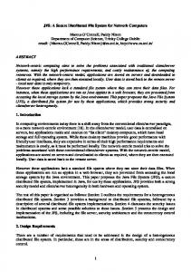
3. OUR PROTOCOL The main components of our protocol are the user client (UCL), light weight front end server (FES), some name node servers (NNS), a resource allocator (RA), block servers (BS) and resource monitors (RM). As shown in Figure 2 users of our file system connect by invoking the UCL. The UCL connects users to the FES. The FES manages sessions with the clients and then forwards the client requests to an NNS. An NNS stores the users file system meta data and reference to a BS which in turn stores the data blocks of a file. The RA tells the NNS which BS and path to BS to use to store data in the BS based on the resource monitor value (rate) it gets from each RM. An RM associated with each BS monitors the resource at its BS and periodically sends a rate metric to the RA.
3. A comparative analysis of our protocol with GFS/HDFS.
3.1 The Algorithm This paper is organized as follows. Section 2 presents related work. In section 3, we present our protocol, in which we discuss the architecture. In section 4, we present numerical results and finally in section 5, we present conclusions and describe scope for future work.
2.
RELATED WORK
Another popular file system for networked computers is the Network File System (NFS) [19]. It is a way to share files between machines on a network as if the files were located on the client’s local hard drive. One of the disadvantages of NFS is that it tries to make a remote file system appear as a local file system, but it’s dangerous to rely on that oversimplification. There are many situations in which the use of NFS (compared to a local filesystem) is not appropriate or reliable. Andrew File System (AFS) [12] is a distributed networked file system which uses a set of trusted servers to present a homogeneous, location-transparent file name space to all the client workstations. AFS has several benefits over traditional networked file systems, particularly in the areas of security and scalability. It is not uncommon for enterprise AFS cells to exceed twenty five thousand clients. AFS uses Kerberos for authentication, and implements access control lists on directories for users and groups. Each client caches files on the local filesystem for increased speed on subsequent requests for the same file. AFS may not be convenient for large scale file systems such as the once handled by GFS. Other examples of works in distribute file system are GPFS [18], Frangipani [20] and InterMezzo [5]. Frangipani is a scalable distributed file system that manages a collection of disks on multiple machines as a single shared pool of storage. The machines are required to be under a common administrator and be able to communicate securely. It has a very simple internal structure which enables them to handle system recovery, reconfiguration and load balancing very easily. GPFS [18] is IBM’s parallel, shared-disk file system for cluster computers. GPFS uses a centralized management scheme which can have scalability issues. In InterMezzo [5], the key design decisions were to exploit local file systems as server storage and as a client cache and make the kernel file system driver a wrapper around local file system. However, they rely on existing protocols such as TCP. Besides these systems do not have a good resource allocation which deals with the dynamic link, storage and processing capacities.
As shown in Figures 2 and 1 our protocol uses the following steps. 1. A user application initiates a session with FES using a UCL. 2. The FES authenticates the user request, finds an appropriate NNS for example by hashing the request ID, and sends the name or ID of the NNS (along with the NNS password) back to the user application. 3. The NNS in turn asks the RA connected to the local switch for an appropriate BS and a path to the BS in which the user application (or another node in the cloud) can store blocks of data or from which it can retrieve the previously stored blocks of data. The RA uses the rate metric it gets from each RM, from it self and other RAs to do the resource allocation. The RA is like a software router. An RA and the network switch can serve as a router. More on how the RA finds the appropriate BS is discussed in section 3.3. 4. The NNS sends name or ID of the BS to the user application and request ID and password to the BS. 5. The user application requests the BS using the information it got from the NNS to store data or retrieve data blocks. 6. The BS authenticates the user request using the information it got from the NNS and continues to transfer data to the user or store data from the user. 7. The RM associated with the BS periodically sends the rate metric which serves as an aggregate resource monitor. After receiving a user request from the FES, the RA finds a BS with more capacity (the highest in the distributed system). Here capacity refers to the link capacity to and from the BS with higher storage and processing capacities in the cloud network. To find a BS with less load (congestion) and hence with more capacity our protocols uses resource monitor metrics from each RM associated with the BS. The algorithms which run in the in the RM and RA are described in sections 3.2 and 3.3 below.
Figure 1: Overview of Our Protocol
3.2 The RM Algorithm A typical cloud network infrastructure is hierarchical as shown in Figure 1. A client application first connects to the FES. The FES chooses the corresponding NNS for the client. The NNS asks the RA for the best BS. The RA finds the best BS based on the metric monitor it gets from the RM server in the BS and other RAs. To find the best BS for a cloud computing operation (for example for updating files), we associate a software resource monitor (RM) with each BS in the cloud. The RM then runs the following algorithm to help RA find the best BS node to store or compute data. 1. The RM monitors the local resources. These resources are the out bound and in bound link, storage and processing backlog (queue size) Q at the BS, the packet (instruction) size ψj and sending rate Rj (in packets, instructions) of node j (which can be a client application using UCL or another BS in the cloud) to the BS, the total number L of packets (instructions) sent to BS by all nodes during a certain control interval d which can be the average of the round trip times (RTTs) of all nodes sending to BS, 2. Each RM computes the minimum of the link, storage and processing fair rates R it can accommodate as κ−Q R = PL ψ j
(1)
j Rj
where κ is the total resource capacity at the BS. The resource capacity is the bandwidth (C) delay (d) product (Cd) in packets if the resource is a link, disk storage
capacity S in data blocks if the resource is a storage and the total number of instructions Cd a node processor with capacity C can process during the control interval d. The inbound and outbound traffic can be dealt separately. 3. The RM calculates and sends the value of R to the RA of its switch every control interval d.
3.3 The RA Algorithm To find the best BS for a cloud computing operation (for example for updating files), we associate a software resource allocator RA to each switch in the cloud. The RA can be placed in a separate computer (server) connected to each switch. The algorithm at the RA is given as follows: 1. The RA associated to a switch receives the uplink and downlink R from each RM of the BS connected to the switch. 2. The RA calculates the uplink and downlink R values associated with the link coming from the higher level switch to the switch the RA is connected to as follows: If the RA can monitor the traffic through the switch, the RA can use equation 1 to calculate the rate R associated with the link from the higher level switch. For the case where it is difficult to monitor the traffic through the switch we can derive the rate metric R associated with the link which connects the local switch with higher level switch using the same equation 1 where Rj in equation 1 is replaced with Rk × Nk . Here Rk and Nk are the rate R and number of flows Nk as calculated by RMk connected to the switch associated
UCL
UCL
UCL
FES
(filename, block index)
UCL
Namenodei = hash(..)
(data)
(block handle, data range)
(block handle)
Instructions
NNS1
NNS2
NNSn
Namespace Chunk Loc.
Namespace Chunk Loc.
Namespace Chunk Loc.
RA
RA
RA
Instructions RM
RM
BS
BS
State
RM
BS
RM
BS
RM
BS
RM
BS
Figure 2: Our Protocol Architecture
with the RA representing the rate at whichP the RM j at the BS j is sending data to the RA, Λ = N 1 Nk Rk is the total arrival rate to the RA where N is the number of RM at the BS sending data to the local switch. If Λ ≤ C, then Q = 0 as there is enough capacity and no queue where C is the total capacity of the link connecting the local switch with the higher level switch. If Λ > C, then Q = d(Λ − C). Then equation 1 becomes R = PN k
κ Nk ψk Rk
(2)
if Λ ≤ C where ψk is the average packet or block or P ψj instruction size at RM k, Nk = d L j Rj and 2κ − dΛ R = PN N ψ k k k
if C > Λ.
(3)
Rk
3. The RA calculates the highest of the R values it obtained from the RMs connected to its switch. Each RA associated with each switch level in the cloud hierarchy keeps minimum of all the Rs of its level and below. 4. When an NNS asks the RA for the best BS for example to store some blocks of data, the RA uses one of the block allocation schemes described in sections 3.3.1.
3.3.1 k-Local Allocation The NNS can decide to store the data blocks within the local switch network (tree) which we call 1-local allocation or the higher switch network (tree) which is the 2-local allocation, or the k the level in the tree which we call k-local allocation.
When a NNS wants to replicate or distribute data blocks into other BSs and if the uplink R of the k + 1st level link is less than that of the kth level R, then it is preferable to do k-local allocation. Otherwise n-Local or Global Allocation is preferred to find less loaded BS in the entire n level (hierarchy) cloud network. The Global Allocation is also preferred when putting a data replica in a remote rack (location) in the cloud is required for safety. For a download (to the BS) case where a client wants to store data blocks in the cloud, the Global Allocation is preferred in order to store find the best BS in the entire cloud. The RA contains a sort of table of IP addresses or ID and rate R values so that when an NNS wants a BS to store data, the BS with the highest R is chosen. Different policies can as well be added to shape the choice of the data allocation level.
3.4 Simplified Examples to Clarify our Protocol 3.4.1 A Client Using a Cloud If a client wants to store a huge data in the cloud, here are the steps which have to be followed: 1. The client contacts the FES as described in Figure 1. 2. The FES authenticates the client, assigns (forwards) the client request to a NNS. 3. The NNS contacts the RA attached to its local switch to find the best BS to store the data. 4. The RA has a table of which local BS has more storage, less loaded path connecting it (the BS) to the first level switch where the client first joins the cloud. The RA chooses a BS for the client and sends to the NNS the
5. The NNS stores the location of the client datablocks and other client file metadata and sends to the client the IP address (ID) of the BS in which the client can store its data and the rate at which the client can send data to the BS. 6. The client then sends data to the BS at the rate the NNS suggested if the network outside the cloud to which the client is connected allows. 7. The algorithms in the RA’s are adaptive updating the rates every control interval (user defined and usually the average of the RTTs). So if the BS the client is using starts to be congested, the RA of that client will see the current rate calculated by the RM connected to the congested BS shrinking and advertises its best (less loaded) BS. All RA’s advertise their new best BS. The NNS which manages the data of the client sending data then chooses a new location for the remaining chunks the client wants to transfer and stores the new location of these chunks. 8. Such a distributed algorithm continues in such an adaptive fashion updating the rates and exchanging the IDs and the rates of the best nodes. A similar approach is used when the client wants to do a huge computation.
3.4.2 A Cloud BS Replicating its Data The second example is when a NNS in a cloud decides to replicate the data in one of the BS’s in its local switch. Such an allocation can be based on a certain policy the file system follows. If the distributed file system wants to keep one replica in the highest level racks, then the RA in the same local switch as the NNS chooses the best remote BS using the above procedures. This is a global allocation scheme. The RA can also use a k-Local allocation scheme based on the policy the distributed file system implements. In this cases the node to which the replicated data is transferred is chosen to be the node which satisfies the filesystem policy and whose path from the originating BS gives the highest rate (throughput).
4. NUMERICAL RESULTS 4.1 Evaluating the FES In our first set of simulation experiments we compared the performance of our protocol against GFS with a varying number of name nodes to show the performance gain of using our FES along with some name nodes. The number of clients used in the simulation is Poisson distributed. It is well documented in the literature that connection files sizes are Pareto distributed [9]. Hence in our simulation the file size of each connection is Pareto distributed. We compared the total update rate of our scheme against HDFS. We use update rate as updating involves reading and writing. In our experiment we used a mean memory access time of 10ns [16]. The GFS master maintains about 64 bytes of metadata for each 64 MB chunk. In the microbench used to evaluate GFS all the machines are configured with a 2 GB
of memory. Therefore the GFS name node should look-up a table of length 2GB/64B. Hence the look-up time for each read/write operation using an efficient algorithm is of order J (2GB/64B). As shown in Figure 3 the update rate of our scheme increases with the increasing number of name nodes when compared with GFS. We used TCP for our scheme just like GFS in order to see the effect of our FES independent of the rate allocation algorithm. 2 GB mem, 64B metadata/64Mb blk Total update rate (blks/s)x1000
IP address or ID of the BS it has chosen and the rate at which the client can transfer data (to the BS).
300 250 200 150 100
GFS Our Protocol 3 NN Our Protocol 5 NN
50 0 0
2000
4000 6000 8000 Number of clients
10000
Figure 3: Update Rate As can be seen from Figure 3 when the number of name nodes increases, the update rate of our scheme increases with the increasing number of active clients. On the other hand the update rate of GFS becomes limited by the capacity of the single name node.
4.2 Evaluating our Rate (Resource) Allocation (RA) Scheme 4.2.1 With no packet loss In this section we show the performance comparison of our scheme against GFS when connections experience no packet loss. As can be seen from Figure 4, our scheme which uses an efficient resource allocation (congestion control and routing scheme outperforms GFS which uses TCP even under no packet loss regime which is the best case scenario of TCP. The chunk transfer time for GFS under a no-packet loss TCP regime can be obtained as follows: If the network bandwidth is C packets per second (pps) with a round trip time RTT, then the maximum TCP window size, W using the TCP window scale option is about C × RT T packets. Now the TCP slow start threshold (ssthresh) until which the TCP congestion window size (cwnd) grows exponentially T (with base 2) is C×RT packets. Hence it takes 2 C × RT T ) 2 rounds for TCP to reach the ssthresh. Until the ssthresh is reached, TCP transmits about t = log2 (
t X i=0
2i = 2t+1 − 1 = ξSS
packets. After the ssthresh, in the congestion avoidance (CA) where the TCP cwnd grows linearly (about 1 packet per round), it takes TCP W/2 rounds to reach the maximum window size, W . From the ssthresh until W is reached, TCP transmits W/2
X
(W/2 + j) = (3W 2 + 2W )/8 = ξCA .
j=1
After W is reached TCP transmits W per round for every round. So the chunk transfer time of a file of size ξ ≥ ξSS + ξCA packets is
Packet losses can be due to sudden traffic spikes or due to regular congestion. For packet loss p due to sudden traffic spikes which last for example for 1 RTT, TCP times out and reduces its congestion window to 1 and its throughput becomes RT CP . Where as our scheme reduces the throughput to (1 − p) × R for only one RTT and sets it back to R for the packet no loss rounds as it gets explicit feedback from the network. If on the other hand the packet loss is due to regular congestion, the throughput using our approach is (1 − p) × R for the congestion times and the throughput of GFS is given by RT CP . As can be seen from Figures 5 to 9 our protocol outperforms HDFS/GFS.
t + W/2 + k rounds such that kW/2 ≤ ξ < (k + 1)W/2.
Chunk Transfer time (ms)
100Mbs link, 10ms RTT, no packet loss 700 600
GFS Our Protocol
500 400
100Mbs link, 10ms RTT, 0.0078 packet loss 800 Chunk Transfer time (ms)
We incorporated the above analytical scheme and the one in the next section in a simulator we wrote in C++.
700 600
GFS Our Protocol
500 400 300 200 100
300
2000
4000
6000
Chunk size (1000 byte pkts)
200 100 1000
2000
3000
4000
5000
6000
Figure 5: Chunk Transfer Time for small files with a packet loss (after TCP reaches its maximum cwnd)
Chunk size (1000 byte pkts)
As can be seen from Figure 4 even if there is no packet loss the chunk transfer time of GFS is limited by the behaviour of TCP which takes many rounds before it can fully utilize the link. If the link capacity increases, the TCP maximum window size increases and hence TCP takes even longer rounds before it reaches the maximum window size to fully utilize the link. This introduces many rounds of unnecessary delay to GFS.
4.3 With Packet Loss The throughput RT CP of a TCP connection given by the famous PFTK formula [15] which is also the same as the throughput formula of the datagram congestion control protocol (DCCP) [14] is ! 1 W q q , min RT T RT T 2bp + T min(1, 3 3bp )p(1 + 32p2 ) 3
0
8
where RT T is the round trip time in seconds, p the packet loss probability, T0 is the TCP retransmission timeout value in seconds and b is the number of packets acknowledged by a single TCP acknowledgement. In our experiment b = 1, RT T = 10ms, T0 = 4RT T as used in [13].
Figure 5 shows that the chunk transfer time increases faster in GFS than our scheme with the increasing chunk size under a packet loss probability no matter how small. In this figure we assume that the first packet loss occurs only after TCP reaches its maximum window size. 100Mbs link, 10ms RTT, 0.0078 packet loss Chunk Transfer time (ms)
Figure 4: Chunk Transfer Time with no packet loss
5000 4500 4000 3500 3000 2500 2000 1500 1000 500
GFS Our Protocol
2000
4000
6000
Chunk size (1000 byte pkts)
Figure 6: Chunk Transfer Time for small files with a packet loss (before TCP reaches its maximum cwnd)
Figure 6 is similar to Figure 5 except that the first packet TCP packet loss in Figure 6 can occur before TCP reaches its maximum window size.
the last chunks of the file can be transferred in with in one or two rounds. This is shown in Figure 8. 100Mbs link, 10ms RTT, 56K chunks (1KB pkts) 12000
45000 40000 35000 30000 25000 20000 15000 10000 5000 0
Chunk Transfer time (ms)
Chunk Transfer time (ms)
100Mbs link, 10ms RTT, 0.0078 packet loss
GFS Our Protocol
20000
40000
60000
Chunk size (1000 byte pkts)
Figure 7: Chunk Transfer Time for large files with a packet loss
Figures 5, 7 and 8 are the best case TCP packet loss scenarios as we assumed that packet loss happens only after TCP reaches its maximum congestion window sizes. If we consider cases where a packet loss can occur any time in the transmission then the performance of GFS can be much worse when compared with our scheme. This is the reason why the performance of GFS does not seem too bad with small size files. In this case the small files get transmitted before the next TCP packet loss event happens. For example as shown in Figure 6 if packet loss occurs even in the first round before TCP reaches its maximum congestion window size then GFS performs worse. 100Mbs link, 10ms RTT, 56K chunks (1KB pkts) 7000 Chunk Transfer time (ms)
10000 9000
GFS Our Protocol
8000 7000 6000 5000 4000
0
GFS Our Protocol
6500
11000
6000
0
0.01 0.02 0.03 Packet loss probability
0.04
Figure 9: Chunk Transfer Time as a function of packet loss probabilities As shown in Figure 9 the performance of GFS doesn’t depend much on how many packets are lost. It just depends more on a packet loss whether it is small or large as TCP decreases it congestion window size when the first packet is lost. However if there are more of such loss periods the performance of GFS degrades as shown in Figure 8.
5. CONCLUSION AND ON GOING WORK The paper presents design of a scalable and efficient distributed file system. The system uses a light weight frontend server to manage sessions and forward requests to many name nodes. This design solves the potential bottleneck scenario that the name node server of current systems can be. The paper also gives an adaptive and efficient resource allocation scheme which can result in full link utilization and hence much reduced chunk transfer time. Based on the numerical results presented, our protocol can outperform well known existing distributed files systems such the GFS and HDFS. Our protocol can be directly implemented in current distributed systems such as cloud computing as an overlay. We are currently working on more detailed experiments. We will also implement our system and test it using the Illinois Cloud Computing Testbed [6].
5500 5000 4500
6. REFERENCES
4000 0
2
4
6
8
10
Number of loss periods
Figure 8: Chunk Transfer Time as a function of number of loss periods with a packet loss probability of 0.0078 As the number of loss periods with a packet loss probability of 0.0078 increases due to congestion in the cloud the performance of GFS degrades considerably until the point where
[1] IDC Cloud Computing. http://blogs.idc.com/ie/?p=224. [2] Improve Namenode Performance. http: //issues.apache.org/jira/browse/HADOOP-3248. [3] Armbrust, M., Fox, A., Griffith, R., Joseph, A. D., Katz, R., Konwinski, A., Lee, G., Patterson, D., Rabkin, A., Stoica, I., and Zaharia, M. Above the clouds: A berkeley view of cloud computing. Technical Report: Electrical Engineering and Computer Sciences University of California at Berkeley UCB/EECS-2009-28 (Feb 2009), 1–23.
[4] Borthakur, D. The Hadoop Distributed File System: Architecture and Design. The Apache Software Foundation, 2007. [5] Braam, P., Callahan, M., and Schwan, P. The intermezzo file system. In Proceedings of the 3rd of the Perl Conference, O¨ı£¡Reilly Open Source Convention, Citeseer. [6] Campbell, R., Gupta, I., Heath, M., Ko, S., Kozuch, M., Kunze, M., Kwan, T., Lai, K., Lee, H., Lyons, M., et al. Open CirrusTM Cloud Computing Testbed: Federated Data Centers for Open Source Systems and Services Research. In Proceedings of the USENIX Workshop on Hot Topics in Cloud Computing (HotCloud) (2009). [7] Cerbelaud, D., Garg, S., and Huylebroeck, J. Opening the clouds: qualitative overview of the state-of-the-art open source vm-based cloud management platforms. In Middleware ’09: Proceedings of the 10th ACM/IFIP/USENIX International Conference on Middleware (New York, NY, USA, 2009), Springer-Verlag New York, Inc., pp. 1–8. [8] Ciurana, E. Developing with Google App Engine. Apress, Berkely, CA, USA, 2009. [9] Downey, A. B. The structural cause of file size distributions. SIGMETRICS Perform. Eval. Rev. 29, 1 (2001), 328–329. [10] Fouquet, M., Niedermayer, H., and Carle, G. Cloud computing for the masses. In U-NET ’09: Proceedings of the 1st ACM workshop on User-provided networking: challenges and opportunities (New York, NY, USA, 2009), ACM, pp. 31–36. [11] Ghemawat, S., Gobioff, H., and Leung, S.-T. The google file system. SIGOPS Oper. Syst. Rev. 37, 5 (2003). [12] Howard, J., Kazar, M., Menees, S., Nichols, D., Satyanarayanan, M., Sidebotham, R., and West, M. Scale and performance in a distributed file system. ACM Transactions on Computer Systems (TOCS) 6, 1 (1988), 51–81. [13] Katabi, D., Handley, M., and Rohrs, C. Congestion control for high bandwidth-delay product networks. In Proceedings of the 2002 conference on Applications, technologies, architectures, and protocols for computer communications (2002), ACM New York, NY, USA, pp. 89–102. [14] Kohler, E., Handley, M., and Floyd, S. Designing dccp: congestion control without reliability. SIGCOMM Comput. Commun. Rev. 36, 4 (2006), 27–38. [15] Padhye, J., Firoiu, V., Towsley, D., and Kurose, J. Modeling tcp throughput: a simple model and its empirical validation. SIGCOMM Comput. Commun. Rev. 28, 4 (1998), 303–314. [16] Park, C., Seo, J., Bae, S., Kim, H., Kim, S., and Kim, B. A low-cost memory architecture with nand xip for mobile embedded systems. In CODES+ISSS ’03: Proceedings of the 1st IEEE/ACM/IFIP international conference on Hardware/software codesign and system synthesis (New York, NY, USA, 2003), ACM, pp. 138–143.
[17] Robinson, D. Amazon Web Services Made Simple: Learn how Amazon EC2, S3, SimpleDB and SQS Web Services enables you to reach business goals faster. Emereo Pty Ltd, London, UK, UK, 2008. [18] Schmuck, F., and Haskin, R. GPFS: A shared-disk file system for large computing clusters. In Proceedings of the 1st USENIX Conference on File and Storage Technologies (2002), USENIX Association, p. 19. [19] Shepler, S., Callaghan, B., Robinson, D., Thurlow, R., Beame, C., Eisler, M., and Noveck, D. Network file system (NFS) version 4 protocol. Request for Comments 3530 (2003). [20] Thekkath, C., Mann, T., and Lee, E. Frangipani: A scalable distributed file system. ACM SIGOPS Operating Systems Review 31, 5 (1997), 224–237.