A Scalable Intra-Domain Resource Management Scheme for Diffserv Networks Haci A. Mantarβ ,φ , Junseok Hwang+ ,α Ibrahim T. Okumusψ Steve J. Chapinφ β Department of Electrical and Computer Engineering, Harran University, Sanliurfa,Turkey φ Department of Electrical and Computer Science, Syracuse University, Syracuse, NY 13244 + School of Information Studies, Syracuse University, Syracuse, NY 13244 α Seoul National University, Seoul, Korea ψ Department of Electrical and Computer Science, Mugla University, Mugla, Turkey Corresponding author: Haci A. Mantar,
[email protected]
Abstract With the rapid growth of the Internet into global communication and commercial infrastructure, the need for Quality of Services (QoS) in the Internet becomes more and more important. With a Bandwidth Broker (BB) support in each administrative domain, Differentiated Services (Diffserv) is seen as a key technology for achieving QoS guarantees in a scalable, efficient, and deployable manner in the Internet. This paper presents the design and and implementation of a new Bandwidth Broker (BB) model to achieve QoS across a Diffserv domain. Our BB uses centralized network state maintenance and pipebased intra-domain resource management schemes. The proposed model significantly reduces admission control time and minimizes scalability problems present in prior research while optimizing network resource utilization. The experimental results verify the achievements of our model. 1 Index Terms Bandwidth Broker, scalability, intra-domain resource management, Diffserv, quantitative QoS.
I.
INTRODUCTION
With the rapid growth of the Internet into a global communication and commercial infrastructure, it has become evident that Internet service providers (ISPs) need to implement quality of service (QoS) to support diverse applications’ requirements (e.g., packet delay, packet loss ratio) with their limited network resources. Integrated Services (Intserv) with RSVP signaling provides per-flow end-to-end QoS guarantees by reserving adequate resources in all the nodes along the path. While this architecture provides excellent QoS guarantees, it has significant scalability problems in the network core because of per-flow state maintenance and per-flow operation in routers. Because of scalability problem with Intserv/RSVP, the IETF has proposed Differentiated Services (Diffserv) [11] as an alternative QoS architecture for network core data forwarding plane, and Bandwidth Broker (BB) [2] for control plane. A. Differentiated Services Differentiated services (Diffserv) requires no per-flow admission control or signaling and, consequently, routers do not maintain any per-flow state or operation. Instead, routers merely implement a small 1
This project is supported by NSF award NMI ANI-0123939.
P25/1
number of classes named Per Hop Behavior(PHB), each of which has particular scheduling and buffering mechanisms. A packet’s PHB is identified with the Diffserv field (DSCP) assigned by the ingress router. To this end, Diffserv is relatively scalable with large network size because the number of states in core routers are independent of the network size. Thus, it is considered as the de facto standard for the next generation of the Internet. However, unlike the Intserv/RSVP, Diffserv only addresses forwarding/data plane functionality, whereas control plane functions still remain an open issue. Hence, Diffserv alone cannot provide end-to-end QoS guarantees. In fact, providing end-to-end QoS is not one of the goals of Diffserv architecture [12]. In particular, these limitations and open issues are: 1)As its name indicates, a PHB defines the forwarding behavior in a single node. Unlike Intserv/RSVP model, there is no QoS commitment for the traffic traversing multiple nodes, or domains; 2)With the exception of Expedited Forwarding (EF) [13], all the PHBs that currently have been defined provide qualitative QoS guarantees. Hence, the requirements of real-time applications, which need quantitative bounds on specific QoS metrics, cannot be guaranteed even in a single node; 3) There is no admission control mechanism to ensure that the total incoming traffic to a node or domain does not exceed the resources for the corresponding PHBs. From the above issues, it is envisioned that Diffserv needs a control path mechanism to achieve endto-end QoS guarantees. The Bandwidth Broker (BB) [2] is one of the strongest candidates for this. B. Generic Intra-Domain BB Issues The Bandwidth Broker (BB) [2] is a central logical entity responsible for both intra-domain and interdomain resource management in a Diffserv domain2 . The goal of the BB is to provide Intserv-type end-to-end QoS guarantees in Diffserv-enabled networks. Upon receiving a reservation request, in general the basic tasks performed by a typical BB [1][2] are: 1) find an appropriate QoS path between ingress and egress routers; 2) obtain up-to-date QoS network state information (which may require communicating with all the routers along the path to obtain their QoS state); 3) reserve resources along this path. In this sense, the BB schemes have several appealing aspects such as relieving core routers from network state maintenance and admission control, optimizing network resource utilization, and alleviating the problems of inconsistent QoS states faced by distributed admission control schemes. However, the BB has its own challenging problems that make the deployment of such a scheme questionable to many researchers: • It is not clear how a BB can obtain up-to-date network state information under dynamic and nonstochastic network traffic conditions. • QoS routing itself is a very complex problem [22] and therefore the route computation time is very long [22]. Since a BB needs to find a path for all the requests, the resulting load will be unacceptably high if it performs this for each individual request. • After finding a path, appropriate resources need to be reserved along the path (adjusting scheduler rate and buffer size). Performing this for each request introduces communication overhead, processing time overhead, and a long admission control time. The model presented in this paper provides scalable and efficient intra-domain resource management for a BB. In particular, this model has scalable maintenance of up-to-date network state information, minimizes scalability in path selection, increases admission probability (and therefore high resource utilization), minimizes admission control time, and provides edge-to-edge quantitative QoS (across its domain) guarantees. Note that the scope of this paper is limited to intra-domain issues. The inter-domain (inter-BB) resource management problems were addressed in our previous work [5]. 2
Although the BB was originally proposed for Diffserv networks [2], it can also be applied to non-Diffserv networks. Because the BB is independent of the forwarding plane schemes.
P25/2
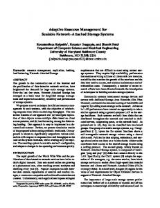
C. Organization of this Paper The rest of the paper is organized as follows. Section II describes a quantitative service model. In section III, we briefly describe the Intra-domain resource management (IDRM) architecture. In section IV, we present the IDRM implementation and show the experimental results. A summary of this paper and motivation of future work are given in Section V. II. Q UANTITATIVE S ERVICE M ODEL As shown in Figure 1, QoS in Diffserv can be categorized into qualitative and quantitative service guarantees. Qualitative services aim to provide per-hop, per-class relative service guarantees [14][18]. There are no worst-case bounds for the given service metrics–each node only guarantees that the services invariant is locally maintained. These QoS metrics are usually a function of the temporal network traffic characteristics, which can vary from connection to connection. The real-time and mission critical applications require quantitative bounds on the service metrics. These service metric bounds must be always satisfied regardless of the temporal traffic characteristics (e.g., Intserv-type hard guarantees), otherwise the service is considered useless. With the exception of EF [13], all PHBs (AF) [14] in Diffserv provide qualitative QoS guarantees. In the following subsection we describe a set of PHBs that can always provide certain level of QoS regardless of dynamic traffic characteristics. A. Quantitative PHB: A quantitative PHB i is associated with an upper delay bound di , an upper loss ratio bound li and certain percentage of link capacity Ci . di is the delay that a packet of i will experience in any router within the domain under the worst-case (congested) network conditions. li is the average loss rate that the packets of i will experience under worst-case network conditions (e.g., di < 3ms, li < 0.01%). It is assumed that each PHB can use only its share of link capacity and the surplus capacity that PHB can be used by best-effort or qualitative services (“QoS class” and “PHB” will be used interchangeably.) Bounds di and li are independent of temporal traffic characteristics (e.g., the utilization level of Ci ). It is assumed that di and li are pre-determined at the network dimensioning (ND) stage [11][12][19][35], which is done in relatively long time intervals (e.g., days, weeks) and downloaded into routers. A router dynamically adjusts its output scheduler rate and buffer size according to the dynamic network conditions to meet pre-determined di and li constraints. These services, of course, require a strict admission control mechanism to limit the incoming traffic rate to the given link capacity for that particular class in order to achieve pre-defined QoS guarantees. An important issue here is that how to determine/estimate instantaneous traffic rate, and how to adjust scheduler rate and buffer size to prevent li and di violation. In the rest of this section we address this issue. 1) Class-based Link Rate Estimation: We use a new class-based measurement-based scheme. In traditional measurement-based paradigms [16][30], the traffic samples are collected at regular small time intervals called sampling period, S , during the duration of a measurement window W (is multiple of S ). Jamin et al [16] have proposed a maximum sampling rate-based approach, where at the end of each W the highest sampling rate is used as the traffic rate estimation for the next W , for Intserv controlled load services. Although Jamin’s model has been widely investigated by many studies, we argue that this model is not be feasible for Diffserv guaranteed services because it does not explicitly take the delay and loss bound into account. It is not class-based, meaning that there is no differentiation among different classes. As illustrated in Figure 6, the rate estimation of the same traffic samples can vary with class-type because P25/3
QoS Classes
Quantitative QoS guarantees
Deterministic guarantees
Parameter-based
Fig. 1.
Qualitative QoS guarantees
Statistical guarantees
Measurement-based
Diffserv class structure
of different delay and loss constraints associated with each class-type. The objective of our class-based rate estimation is: Given a class QoS constraints (di and li ), estimate the traffic rate each class in each link based on the online real-time measurement statistics. With the assumption that a large number of reservations are being aggregated into the same queue and therefore share the same resources, we model the traffic envelope of a link as Gaussian (Normal) distribution under the conditions of the Central Limit Theorem (CLT) [15][27]. The CLT states that the aggregation rate approaches a Gaussian distribution when the number of aggregated reservations is large [4][5]. There are several advantages to using this model. • From the given definition, the Gaussian distribution becomes a more realistic model for the Diffserv network to estimate the traffic rate of a class, or link utilization because of the coarse granularity of the aggregation. The individual reservations’ traffic rate fluctuations are smoothed due to aggregation. • The aggregate traffic can simply be characterized by mean and cumulative variance alone. • The rate can be estimated based on pre-defined QoS metrics [4][19]. In other words, class-based rate estimation is possible. For example, a class’s traffic rate can be estimated based on its tolerable loss ratio (Figure 6). Let’s donate mi as the mean traffic rate of sampling period (S ) i, N as the number of samples in a P 2 window W , m as the mean traffic rate of a W (m = N1 N i=1 mi ), σ as the average variances of N P N 1 2 2 samples (σ = N i=1 (mi − m) ) , R as the predicted traffic rate, and X as the instantaneous traffic rate. To meet the pre-defined l and d, the following equation must be satisfied: P r(X > R) < l
(1) can be solved with the well-known normalized Gaussian approximation [15]. R−m Q( )≤l σ R 2 where Q(x) = √12π x∞ exp−y /2 dy = 21 erf c( √x2 ), in order not to exceed l R = m + Q−1 (l)σ
(1)
(2)
(3)
Equation (3) computes the link traffic rate with respect to l. The multiplier Q−1 (l) controls the estimation rate to meet the constraint l. As is seen, by changing the l, the estimated rate can vary. Since, the delay is one of the constraints, the value of W is set based on the class’s delay bound d. That is, W = d − 4d; 4 is a cushion to prevent delay violation that may come from the scheduler. P25/4
2) QoS Enforcement:: For per-node QoS enforcement we present a simple but effective per-node provisioning algorithm. A router dynamically adjusts the corresponding scheduler rate based on measured rate described above to meet the pre-defined QoS constraints (l and d). The scheduler rate Rs is simply defined as: Rs ≥ buf f er − size ∗ d. Since d and l are pre-defined, each router adjusts its scheduler rate independent from other routers, sources of traffic, or any party (e.g., a BB, policy server). Under this premise, each router provides the desired QoS regardless of the utilization rate as long as the aggregate traffic rate does not exceed the link rate for that the particular PHB. Note that these worst-case bounds are for heavily-load conditions, for lightly-loaded conditions delay and loss ratio rate are, of course, less than d and l. An important point here is that a router do not perform per-flow or aggregate admission control. The admission control, in our model, is performed by a third-party server described in next section. B. Edge-to-edge QoS (PDB) The second step toward a scalable end-to-end QoS is to provide edge-to-edge (from ingress router to egress router) within a domain, called Per Domain Behavior (PDB) [12] by IETF.(From now on, the terms ”PDB” and ”edge-to-edge QoS” will be used interchangeably.) A PDB QoS defines the upper bounds of QoS constraints that identifiable packets will receive across a domain regardless of the network utilization. PDBs, as QoS building blocks, are intended to be useful tool for managing a Diffserv domain. This level of abstraction makes it easier to compose cross-domain services as well as to hide details of a network’s internals while exposing information sufficient to enable QoS. Since the worst-case properties of a PHB (di and li ) are the same in all the nodes within a domain, the edge-to-edge QoS service characteristics, , can be simply represented in terms of di and li . A PDB for a P IR-ER pair and QoS class i can be represented as: P DBIR,ER,i =< IR, ER, Di , Li >. (Di = N j=1 dij , QN Li = j=1 (1 − lij ) where j represents a node and N represents the number of nodes along the path. In this work, a PDB also represents the QoS associated with an intra-domain pipe described in the next section. Note that since the link resources allocated for a PHB can only be used by that PHB, the network can be considered as if it is divided into multiple virtual networks, one per class. Thus, in the rest of this paper, it is assumed that there is only one QoS class within a domain. An important feature of this service model is that the NP-complete QoS routing problem [22] can be simplified. Since a PHB has the same worst-case constraints in all the nodes, the routing problem can be simplified to the number of hop counts and bandwidth constraints. III. I NTRA - DOMAIN R ESOURCE M ANAGER A RCHITECTURE A. Overview The intra-domain resource management architecture illustrated in Figure 2 relies on a centralized server called an intra-domain resource manager (IDRM). The IDRM maintains detailed QoS network state information (e.g., class-based available BW in each link), and presents this information to the BB in an abstracted fashion. The IDRM does not perform any policy related task such as SLA and SLS checks and users account management. Consequently, it has no interface with customers (end hosts or customer domains). It can be considered as a module with which the BB interacts to get network state information for intra-domain admission control. The idea here is to reduce the online operation complexity of a BB by having complex and computationally intensive tasks done by IDRM in advance. The IDRM has several relational database components to maintain and manage network state information: P25/5
Intra-Domain Resource Management (IDRM) Topology db
QoS db
Pipe db
Link state db
Pipe state updates
QoS state updates
Incoming traffic
Ingress router
Outgoing traffic
pipes
Egress router
Core routers Ingress router
Fig. 2.
IDRM functional architecture
QoS Information database contains the QoS parameters associated with each PHB. This can be considered as static information in the sense that it is updated only at the network configuration time. PHB:. The Domain Topology database contains the mapping connections among routers and it is static. The Link State Database is structurally very similar to the OSPF routing information base (RIB). It keeps class-based (PHB-based) QoS state information of all the routers in the form of: . This database is dynamically updated based on network conditions. The Pipe Database stores the states of the pipes established between each IR − ER pair and a particular PHB in the form of: . This database is the abstraction of complex domain topology in terms of network state information and is dynamically updated with network conditions. The first step in managing network resources is to obtain accurate link state information. For this, the IDRM uses two different paradigms. First, by having domain topology and the links’ QoS state information such as supported PHBs and their associated link capacity in its database (Figure 2), the IDRM centrally updates and maintains the link state database as resources are assigned to and released from a reservation without interacting with the links to get their actual QoS state. Thus, the IDRM keeps track of reserved and available BW on each link in its database. This is a typical BB approach used for deterministic QoS services such as VLL [13]. Second, the IDRM dynamically obtains links’ QoS information from routers. In this paradigm, each router within the domain sends its link state QoS information (for each interface-PHB pair) directly to the IDRM (as depicted in Figure 2) rather than flooding to all other routers as is done in traditional link state protocol [25][26]. In this approach, the IDRM is the only entity that has complete knowledge of domain topology and each link’s QoS state information. Unlike link state protocol, where each router needs to maintain QoS information about all the routers, here a router needs to maintain only its links’ QoS information. Thus, the communication, computation and storage overhead are substantially reduced. The next and most challenging step is: upon receiving a QoS request to find a path that has sufficient resources. For this, the IDRM relies on a pre-established pipe (tunnel) model. Given the domain topology P25/6
and QoS (PHB) supported by each node at the configuration stage [1][12][35], the IDRM pre-establishes pipes between each possible IR-ER pair for each PHB (). A pipe can be an MPLS tunnel (LSP), which is called trunk when it is used for Diffserv classes, or it can rely on traditional IPforwarding where the packets associated with a particular destination address prefix (IP/X, where X triple as done in traditional routing schemes such as OSPF. This may still result in poor network utilization, even though the IDRM dynamically resizes pipes. To increase the utilization, multi-pipe may need to be established for each < ingress, egress, P HB(P DB) > as proposed in [36]. Although, for simplicity, we do not consider this situation in this paper. But the IDRM has flexibility to support multi-pipe paradigm. C. Network State Maintenance This section describes the methods used to maintain the “link state database” and “pipe database”. In particular, it addresses two key problems: how to estimate/determine the traffic rate in a pipe and node, and how to update the associated databases. The solutions of these problems can vary, depending on the service types (deterministic or statistical). Two different schemes are presented, Parameter-based Centralized Update and Measurement-based Distributed Direct Update. 1) Parameter-based Centralized Management: In this method a BB updates the link state and pipe databases based on the requests’ traffic descriptor parameters rather than interacting with routers to get the actual traffic rate. Upon granting a new reservation or releasing an existing one, it updates the corresponding pipe resources (utilization rate) accordingly. When a pipe’s utilization exceeds its utilization upper bound, where pipe resizing process is invoked, the IDRM updates the link state database based on the aggregated change rather than on a per-request basis. In the following, we describe two schemes: deterministic and statistical models. Deterministic Model: It is assumed that a reservation request can be characterized by (m, r), where m and r represent the mean and the peak rates of the traffic, respectively. For deterministic services, the IDRM updates the corresponding pipe based on the peak rate, independent of whether the source transmits continuously at peak rate or not. The reservation rate of a pipe, R, with N reservations can be simply expressed as: R=
N X
rj
(6)
j=1
The new request is accepted if the sum of the peak rates of all the existing reservations plus the peak rate of the new reservation rnew is less than the pipe size, P size . That is: R + rnew ≤ P size
(7)
Under these conditions, every reservation gets BW equal to its peak rate, thus the packets will not be affected by queuing delay or loss due to congestion, regardless of whether reservations are aggregated or not. This scheme can be used for Diffserv EF, known also as “virtual leased line” (VLL)[13], or QPS [1], which requires no queuing delay and has no loss due to congestion. The peak rate-based estimation is very simple, because only knowledge of the peak rate of reservation is required. However, it is envisioned that applications of this scheme are very limited [1][2], because it results in low resource utilization. In the following, an alternative method is presented for those services that can tolerate statistical QoS guarantees.
P25/10
2) Statistical Model: In this approach a source reserves a specific BW between its mean rate and peak rate by tolerating limited delay and loss to increase utilization. The challenging problem here is how to determine required BW from a request’s traffic descriptor parameters. To simplify this problem, various effective bandwidth schemes [17]have recently been proposed. However, it has been shown that such schemes are computationally intensive and that they do not exploit the advantages of statistical multiplexing [15][27], which is so important for Diffserv networks where the aggregation of a large number of reservations possible. By assuming that a large number of reservations are being aggregated into the same queue and therefore share the same resources, the IDRM uses a Gaussian (Normal) approximation model under the conditions of the Central Limit Theorem (CLT) [15][27]. The CLT states that the aggregation rate approaches a Gaussian distribution when the number of aggregated reservations is large. There are several advantages to using this model. First, from the given definition, it is seen that the Gaussian distribution becomes a more realistic model for the Diffserv network to estimate the traffic rate of a class, link, or pipe utilization because of the coarse granularity of the aggregation. The individual reservations’ traffic rate fluctuations are smoothed due to aggregation. Second, the traffic can simply be characterized by mean and cumulative variance alone. Third, the rate can be estimated based on pre-defined QoS metrics. In other words, class-based rate estimation is possible. For example, a class’s traffic rate can be estimated based on its tolerable loss ratio (Figure 6). In the following we describe how the IDRM can use the Gaussian model to estimate the traffic rate in a pipe. We denote m as the average rate and σ 2 as the variance of a reservation request of a particular class (PHB) that has delay bound d and loss bound l. It is assumed that all the reservations are independent and identically distributed (i.i.d). At time t, the instantaneous traffic rate of a pipe with N reservations is: R(t) =
N X
ri (t)
(8)
j=1
Where ri (t) represents an individual reservation’s traffic rate and R(t) represents the aggregate traffic rate in the pipe at time t, the aggregate reservation mean rate, ma , and variance, σa2 , can be expressed as: ma = N m, σa2 = N σ 2 . For large N , R(t) tends to the Normal distribution under CLT [15][27]. Under the assumption of a bufferless system, to meet QoS requirements the following probabilistic condition must be held: P r(R(t) > P size ) ≤ l
(9)
(4) can be solved with the well-known normalized Gaussian approximation [15]. (Readers are referred to [27] for the details of Gaussion approximation.) Q(
where Q(x) =
√1 2π
R∞ x
exp−y
2
/2 dy
P size − N m √ )≤l Nσ
(10)
= 21 erf c( √x2 ), in order not to exceed l
√ P size ≥ N m + Q−1 (l) N σ
(11)
√ R = N m + Q−1 (l) N σ
(12)
P25/11
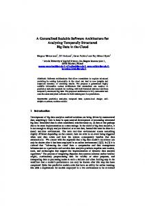
A new reservation request is admitted if equation (6) is satisfied, where N is the sum of the number of current flows in the pipe plus the number of requested flows. Once a request is granted, the IDRM updates the corresponding pipe in the pipe database based on the result of (7). The effect of statistical multiplexing can be seen from (7). The reservation rate in the pipe does not increase linearly with the number of reservations. From (7) the equivalent capacity of a reservation can be found as: ceq =
R σ = m + Q−1 (l) √ N N
500 450
Peak Mean equivalent
400 350 Bandwidth
(13)
300 250
L=0.0001
200 L=0.03
150 100 50 0
Fig. 6.
10
20
30
40
50
# reservations
60
70
80
The change of equivalent BW vs. number of aggregated reservations
As shown in Figure 6, the equivalent (effective) reservation rate of a request approaches its mean rate as the number of aggregated reservations in the pipe increases, consequently utilization increases. The figure also shows the sensitivity of a reservation rate to l. The reservation rate decreases as l increases. This means that the utilization of a pipe can be increased with respect to l. It is also observed that the rate estimations of two classes can be different if they have different loss ratio constraints even if their actual traffic rate is the same. Another important point here is that the loss rate, in practice, will always be less than l because of the effect of the system’s buffer. In this section the buffer effect is not taken into account because of the analytical complexity that comes with buffer parameter. However, this will be considered in the next section when the measurement-based scheme is presented. 3) Link State Database Update: The key point in a parameter-based model is that an IDRM accesses and modifies the link state database only when it needs to modify a pipe size, rather than accessing for each individual reservation request it receives. When a pipe needs to be re-sized, each pipe updates the corresponding links’ sizes with their current aggregated utilization state. The new state in a link will be simply the sum of the reservation rate of all the pipes that use the link. The advantages this scheme is that an IDRM might handle a large number of requests (granting new or terminating existing reservations) without the accessing link state database and modifying the corresponding links’ states. This is important, especially when aggregation granularity is high. Consider a backbone domain where the load of a pipe is predictable and changes slowly [30], an IDRM might not access and modify the link state database for a long time period (e.g., hours). D. Measurement-based Distributed Direct Update In this approach, the traffic rate of a pipe and link is estimated based on online real-time measurement statistics collected from the routers. Each router dynamically measures the aggregated traffic rate of each P25/12
class on its interfaces, based on the delay, d, and loss, l, constraints associated with that class, and updates the link state database accordingly. Unlike traditional link state protocol-based update schemes [26], in this scheme each router is configured to send its QoS state directly to the IDRM rather than flooding to all the routers within the domain (Figure 2). The IDRM is the only entity that keeps track of the QoS states of all the links within the domain. Thus, a router needs to maintain only its links’ QoS state rather than information about all the links within the domain (assuming that the domain has only one routing area) as is done in traditional links state protocol. For pipe database update, the ingress router measures the traffic of rate in each pipe that it carries and updates the pipe database when a significant change is detected (Figure 2). 1) Update Conditions: An update condition determines when a node should update the link state and pipe database with its current QoS states. The most accurate approach would be to update at the lowest possible time intervals such as at the end of every window, W . However, this is very expensive in terms of signaling and processing. To avoid the above problem, this model uses a threshold-based triggering scheme inspired by [34] for link state and pipe database updates. A new update is sent when the change in available bandwidth since the last update exceeds the predetermined threshold (th). A node sends the update messages to the link state database when the current traffic rate Rc is significantly different from the previously advertised value of traffic rate Rp . That is: k Rc − Rp k ≥ th (14) Rc The value of th has a significant effect on the update frequency. The smaller th results the more accurate state, but the communication and processing overhead is higher. On the other hand, the larger th may cause a more inaccurate state. A key tradeoff is therefore to choose an appropriate th size. In this model, the value of th varies with respect to the utilization level. That is, when the link is lightly loaded, th is high, meaning that the frequency of the update messages is low. An inaccurate link state will not have much effect on link utilization. When the link is heavily loaded, th is low, meaning that the frequency of update messages is high. This is because in a heavily loaded case, the more accurate link state may result in higher utilization. Based on these conditions, a th is formulated as: C − Rc (15) C where C is the link capacity for that particular class and λ is a constant. A node update message includes the state of all the interfaces. The format of an update message is as follows: . The above conditions are the same for pipe database updates. The format of a pipe update message is: . th = λ
IV. I MPLEMENTATION R ESULTS We implemented IDRM in conjunction with our inter-domain BB scheme described in the next section. We evaluated the scalability of IDRM in terms of link and pipe database update. The trades off between scalability and resource utilization were provided under various traffic loads in the network. In general, the implementation consists of the following main components: Network Monitoring Tool (NMT) estimates online link and pipe utilization with the measurementbased method described in the previous section and updates the corresponding databases in IDRM. The NMT has three parameters: sampling period S (this, to some extent, defines the tolerable delay/buffer-size of a node), window size W , and loss control parameter η (Q−1 (l)). These parameters are class-specific P25/13
and pre-determined based on a class quantitative PHB. The NMT is located in both edge/border and core routers. While the core routers estimate only the class-specific aggregate traffic rate in their interfaces, the ingress and egress routers estimate the traffic rate in the pipes in addition to the interfaces’ rate. Note that since a link and pipe utilization rate are estimated according to their class-specific QoS parameters (e.g., packet loss ratio), we do not need to monitor QoS parameters (or perform admission control based on instantaneous QoS metric values). Although QoS metric values of a link can dynamically vary with temporal traffic characteristics, these variations are under certain bounds, which do not violate the associated classes’ commitments. Relational Databases: The IDRM uses relational databases to maintain pipe and link states. Currently, each router sends its state directly to the corresponding database. The communication between routers and the databases is handled via a long TCP session. Forwarding path: We used iproute2 [31], which has advanced traffic control functionalities, for traffic conditioning and queuing. In all the experiments we applied Class-Based Queuing (CBQ) [3]. The traffic that exceeds its profile is simply dropped. For all the experiments, we used the topology shown in Figure 7. Each ingress router (IR1 and IR2) has 10 source nodes that request reservations to any node in the destination domain. Each link in the domain has a 10Mbps capacity for priority traffic, and all the links are unidirectional. The link traffic rate estimation and update schemes were evaluated on link L3, which is the bottleneck link in this scenario. There are two intra-domain pipes, P 1 and P 2, which span over the paths L1 − L3 and L2 − L3, respectively. The P 1 and P 2 traffic rate estimations were performed at the corresponding ingress routers IR1 and IR2, respectively. BB/IDRM Host
BB Host
IR1 Host
10Mbps
Host
L1
10Mbps
L2
CR
10Mbps
L3
Host
IR2
Diffserv core domain
Host
Host
Host
ER Bottleneck Link
Destination domain
Host
Linux Router
Source Networks
1
P
10A C
1T M A
0C T
M
C O H
LC
O
L
2
3
45
6
7
8
910
1
12
1
2
3
4
5
31
415
16
718
19
20
12
23
24
13
14
15
16
1
6
7
8
9
18
19
20
2
1
0
1
1
1
2
2
2
3
2
4
R W
U W S
C IT
1
7
1
L P
Alcatel Switch
K IN
2
Fig. 7.
Experimental network topology
Traffic Model: The source nodes connected to IR1 and IR2 were configured to make reservation requests according to a pre-determined reservation rate. The traffic rate can vary between minimum, mean, and maximum rates. The mean rate of a reservation varies according to a rate profile created based on traced data from a real network [32]. The minimum and the maximum traffic rates were set to 70% and 140% of mean rate, respectively. Reservation requests were made based on the maximum traffic rate (peak rate). Once a reservation was granted, the host immediately triggered the traffic generator to send traffic. Each node had multiple simultaneous reservations between 5 and 10. The average number of simultaneous reservations for each source network was 35. The duration of a reservation is exponentially distributed with a mean of one minute. In the first set of experiments, we explored the effectiveness and the accuracy of the NMT for link state maintenance and update. As mentioned earlier, the traffic rate estimation can vary with class-specific P25/14
QoS and measurement parameters including η , S and W . Figure 8 shows the effect of W in traffic rate estimation and scalability in link database update. In this experiment we set η =2.5, which corresponds to a 0.621% loss ratio and S =1 millisecond. The measurements were performed for W = 1, W = 10 and W = 100 seconds under a heavy load network condition. As depicted in the figure, the accuracy of rate estimation varies with W . The 1-second window has the most accurate rate estimation, and it is sensitive to small time-scale traffic rate fluctuations. On the other hand, the 100-second window has the least accurate rate estimation, and does not follow small time-scale traffic rate fluctuations. As a consequence, it degrades QoS performance and causes poor resource utilization. 8 Actual traffic rate
W=100sec
W=10sec
W=1sec
7
6
BW(Mbps)
5
4
3
2
1
0 50
100
150
200
250
300
350
400
450
Time (seconds)
Fig. 8.
The effect of W in a link traffic rate estimation
The Table 2 shows the trade-off between window size and the number of admitted reservation requests during a 20 minute period. (ρ=the average reservation demand/pipe size.) From these results, it is observed that, under lightly-loaded (relatively) network conditions, setting W to a smaller value does not significantly increase the link utilization compared to the update overhead that it causes. For example, while for ρ = 0.8 the numbers of admitted requests for 10-second and 100-second windows are very close to each other, the update frequency of 10-second window is 10 times larger than the update frequency of 100-second window. The effect of window size in resource utilization is significant only when the network is heavily loaded. window size 10 50 100
ρ=1 563 461 359
ρ=0.9 661 641 611
ρ=0.8 691 687 681
ρ=0.7 700 700 700
TABLE II T HE EFFECT OF VARIABLE WINDOW SIZE ON
THE NUMBER OF ACCEPTED RESERVATION REQUESTS UNDER DIFFERENT NETWORK LOADS .
In the second experiment (Figure 9), we evaluated the effect of W in a pipe resource estimation and pipe-based admission control scheme, which is a combination of both parameter- and measurementbased methods. The pipe size was fixed (set to 2Mbps), meaning that no pipe-resizing process takes place during the duration of the experiment. The average reservation demand to use the given pipe resources was 3Mbps, which is the aggregated demand from 35 sources. The mean, minimum, and maximum P25/15
traffic rates of a reservation were set to 100, 80 and 140Kbps, respectively. (This is the average of an IP telephony session with no compression.) This setting allows us to examine the pipe utilization under a heavily-loaded network condition. 2.5 Tunnel Capacity
W=10sec
W=50sec
W=100sec
2
BW (Mbps)
1.5
1
0.5
0 0
10
20
30
40
50
60
70
80
90
100
Time (10 second)
Fig. 9.
A pipe utilization with variable window size under heavily loaded network conditions.
The ingress router (R1) sent the up-to-date pipe utilization state to IDRM with an interval of W . When an IDRM granted a new reservation, it simply updated the pipe database according to the peak rate of the reservation. When there were no available resources left, the new incoming requests were rejected. Once the measurement results arrived, the pipe size was immediately updated with the new results. Figure 9 depicts the pipe utilization with respect to variable window sizes. As expected, increasing the W decreases the pipe utilization. During the entire duration of the experiments, 611, 439, and 357 reservations were accepted for 10, 50, and 100 seconds window sizes, respectively. From the above experiments, it is seen that there is a clear trade-off between the frequency of database update and resource utilization. While a 1-second window estimated the most accurate link and pipe utilization, it introduced the highest update overhead. On the other hand, a 100-second window had the least update frequency but caused inefficient resource utilization (under heavily loaded network conditions), because the available resource on a link or in a pipe remained unknown during the entire duration of W and the admission control decisions during this period were performed based on worst-case conditions (peak rate based). Note that the above experiments were performed under heavily-loaded network conditions. In practice, however, a link’s resources may not be overloaded most of the time [30]. As mentioned in before, when the network is under-utilized (relatively), varying the database update intervals does not cause significant changes in resource utilization. Table 3 shows the results of the database-update scheme, where a router use a small window in traffic rate estimation, but updates the database only when a significant change occurs in link/pipe utilization (when the utilization exceeds th). window size 10 20 40
th=1% 115 55 29
th = 5% 93 41 25
th = 10% 71 33 21
th = 15 49 27 13
TABLE III T HE EFFECT th THE NUMBERS OF DATABASE UPDATE .
P25/16
Fig. 10.
Fig. 11.
Class-based traffic rate estimation
The classes’ loss ratio with respect to η
In the next set of experiments (Figures 10 and 11), we evaluated the performance of measurementbased scheme under class-specific QoS constraints. We defined three different classes that have η =1.5, η =2, and η =3, which in turn represent a 6%, 2.27% and 0.1% loss ratio. The window size was set to 10 seconds for the entire duration of the experiment. As shown in Figure 10, the rate estimation over the same set of traffic samples varied with classes’ loss ratio constraints. The trade-off here is between resource utilization and the class’s QoS performance. While the lower η (higher tolerable loss ratio) achieves higher resource utilization, it substantially degrades the QoS by dropping some packets (Figure 11). On the other hand, the higher η increases the QoS, but results in overestimation. Figure 11 shows the importance of Gaussian approximation in achieving the given QoS constraints. For measurement intervals of 10 milliseconds Class 1 (η =1) and class 2 (η =2) met their given loss-ratio constraints with 98.1% and 99.92, respectively. There was no packet lost in class 3 (η =3). Figure 12 depicts the achievement of the measurement-based scheme compared to the parameter-based scheme in pipe utilization. The pipe size and the average incoming reservation demand were set to 2Mbps and 2.5Mbps, respectively. As expected, the measurement-based scheme has much higher utilization than the parameter-based. Even when the loss ratio was 0.1% (which is less than the tolerable loss ratios of most of real-time applications), the average pipe utilization was increased about 20%. This validates the efficiency of using the measurement-based admission control scheme for the services that can tolerate statistical QoS guarantees. P25/17
Fig. 12.
Measurement-based vs. Parameter-based in pipe utilization
V. C ONCLUSION
AND
F UTURE W ORK
In this paper we have designed and implemented an intra-domain resource manager (IDRM) for quantitative QoS guarantees across a BB-supported Diffserv domain. The IDRM uses centralized network state maintenance and pipe-based intra-domain resource management schemes. The proposed model significantly reduces admission control time and minimizes scalability problems present in prior research while optimizing network resource utilization. In the future we will work on the intra-domain traffic engineering problems in BB-supported Diffserv model. We will also investigate the reliability of the BB. R EFERENCES [1] QBone Signaling Design Team, “Simple Inter-domain Bandwidth Broker Signaling (SIBBS)”, http://qbone.internet2.edu/bb/ work in progress. [2] K. Nichols, V. Jacobson, and L. Zhang. “ A Two-bit Differentiated Services Architecture for the Internet” RFC 2638, July 1999. [3] S. Floyd, V. Jacobson, “Link-Sharing and Resource Management Models for Packet Networks,” IEEE/ACM Transactions on Networking, v.3, n.4, Aug. 1995. [4] Haci Ali Mantar, “Scalable Resource Management Framework for QoS-Enabled Multi-Domain Networks” Ph.D Thesis, Syracuse University, August 2003. [5] Haci Mantar, Junseok Hwang, Steve Chapin, Ibrahim Okumus ”A Scalable Model for Inter-Bandwidth Broker Resource Reservation and Provisioning”, accepted to IEEE Journal of Selected Areas in Communication. [6] Mantar, Haci, Hwang, Junseok, Okumus, Ibrahim and Chapin, Steve (2001) “Inter-Domain Reservation via 3rd Agent”, SCI 2001/ISAS 2001, July, Orlando, USA. [7] Haci Mantar, Junseok Hwang, Steve Chapin,Ibrahim Okumus, “A Scalable and Efficient Inter-Domain QoS Routing Architecture for DiffServ Networks”, IEEE IM2003, March 2003. [8] Ibrahim T. Okumus, Junseok Hwang, Haci A. Mantar, Steve J. Chapin; “Inter-Domain LSP Setup Using Bandwidth Management Points”, Globecomm2001. [9] E. Rosen, A. Viswanathan, R. Callon “Multiprotocol Label Switching Architecture”, RFC 3031. [10] Chen-Nee Chuah, “A Scalable Framework for IP-Network Resource Provisioning through Aggregation and Hierarchical Control”, Ph.D thesis, University of California at Berkeley, 2001. [11] S. Black et al., “An Architecture for Differentiated Services,” RFC2475, Dec. 1998. [12] K. Nichols, B. Carpenter “Definition of Differentiated Services Per Domain Behaviors and Rules for their Specification” RFC 3086. [13] V. Jacobson, K. Nichols, K. Poduri, “An Expedited Forwarding PHB,” RFC2598, June 1999. [14] J.Heinanen, F. Baker, W. Weiss, J. Wroclawski, “Assured Forwarding PHB Group,” RFC2597, June 1999. [15] Anhanasios Papoulis, ” Probability, Random Variables, and Stochastic Process”, Third Edition, McGraw-Hill 1991 [16] S. Jamin, P. B. Danzig, S. J. Shenker, and L. Zhang, “A Measurement-based Admission Control Algorithm for Integrated Services Packet Networks,” ACM/IEEE Transactions on Networking, 5(1):56-70, Feb. 1997.
P25/18
[17] C.-S. Chang and J. A. Thomas, “Effective Bandwidth in High Speed Networks,” IEEE JSAC, vol. 13, 1995, pp. 1091 1100. [18] R. Liao, A. Campbell, “Dynamic Edge Provisioning for Core IP Networks, ” Proc. of the 8th International Workshop on Quality of Service, IEEE IWQoS 2000, Pittsburgh. PA, USA, June 2000. [19] Mantar, Haci, Hwang, Junseok, Chapin, Steve, Okumus, Ibrahim, “A New Inter-Domain QoS Routing Architecture for QoS-enabled Networks” Communications and Computer Networks (CCN 2002) November 4-6, 2002 Cambridge, USA. [20] Ibrahim Khalil and Torsten Braun: “Edge Provisioning and Fairness in VPN-DiffServ Networks,” Journal of Network and System Management Vol. 10, No. 1, March 2002. [21] Fred Baker, Carol Iturralde, Francois Le Faucheur, Bruce Davie “Aggregation of RSVP for IPv4 and IPv6 Reservations,” RFC3175,September 2001. [22] Zheng Wang, Jon Crowcroft, “Quality-of-Service Routing for Supporting Multimedia Applications,” IEEE JSAC 1996 14(7): 1228-1234 (1996) [23] L. Cruz, “Quality of Service Guarantees in Virtual Circuit Switched Networks,” IEEE JSAC, special issue on ”Advances in the Fundamentals of Networking” (vol. 13 no. 6), August, 1995. [24] Nicolas Christin, Jrg Liebeherr and Tarek F. Abdelzaher. A Quantitative Assured Forwarding Service. In Proceedings of IEEE INFOCOM 2002. [25] P. Aukia, M.Kodialam,P.Koppol, “RATES: A server for MPLS Traffic Engineering”, IEEE network magazine, March 2000. [26] J. May “OSPF Version 2”, IETF RFC 2178, july 1997. [27] Matthias Grossglauser, David N. C. Tse: A framework for robust measurement-based admission control. IEEE/ACM Transactions on Networking 7(3): 293-309 (1999). [28] Paxson, V, and Floyd, S., “Wide-Area Traffic: The Failure of Poisson Modeling,” IEEE/ACM Transactions on Networking, Vol. 3 No. 3, pp. 226-244, June 1995. [29] Traffic Generator Software, http://www.postel.org/tg/ [30] Knightly and J. Qiu, “Measurement-Based Admission Control with Aggregate Traffic Envelopes,” IEEE IWDC ’98 Italy, Sep.1998. [31] http://snafu.freedom.org/linux2.2/. [32] http://www.caida.org/dynamic/analysis/workload/sdnap/. [33] T.Li and Y. Rekhter.”A provider Architecture for Differentiated services and Traffic Engineering RFC2490. [34] R. Guerin, A. Orda, and D. Williams. “QoS Routing Mechanisms and OSPF Extensions.” Proceedings of 2nd Global Internet Miniconference (joint with Globecom’97), Phoenix, AZ, November 1997. [35] P. Trimintzios et al. “An Architectural Framework for Providing QoS in IP Differentiated Services Networks”, IEEE IM2001. [36] A. Elwalid, C. Jin, S. Low, and I. Widjaja, ”MATE: MPLS Adaptive Traffic Engineering”, IEEE INFOCOM 2001. [37] X. Xiao, A. Hannan, B. Bailey, S. Carter, L. M. Ni, ”Traffic Engineering with MPLS in the Internet”,IEEE Network magazine,March 2000. [38] Junseok Hwang, Steve Chapin, Haci Mantar,Ibrahim Okumus, ”An Implementation Study of a Dynamic Inter-Domain Bandwidth Management Platform in DiffServ Networks”, IEEE IM2004
P25/19