A Service Oriented Architecture for CAX Concurrent Collaboration A. Khaled, Y. Ma*, and J. Miller
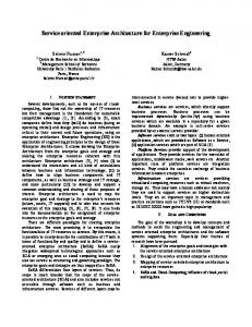
technology; Difficulty in synchronizing changes that might raise conflicts that require human interaction to resolve it; and o No possibility for concurrent collaboration on the product model. The machine-to-machine automatic interactions are difficult to realize with the current tools and the use of custom components for information transformation, translation and exchange is not satisfactory. Many of the operations related to CAX information exchange is performed manually using out-of-band processes, such as file ftp, disks, etc. In the current point-to-point CAX integration approach, an adapter or a custom build component must be built that takes care of the translation when exchanging information between two systems. The number of adapters increase based on the formula n2, where n is the number of interacting CAX systems. Fig. 1 describes the situation in a point-to-point integration. The situation becomes unmanageable when CAX tools evolve independently breaking the functionality of adapters’ implementations.
Abstract —The competitive and open market nature demands different vendors to collaborate during the product life cycle and to reduce the product’s time to market. In this paper, we propose an infrastructure to enable the concurrent collaboration of heterogeneous CAX tools at the feature level using a Service Oriented Architecture (SOA) approach. A Feature Markup Language (FML) is proposed as the modeling language for feature representation and exchange which can be independent to operating system and programming language. How to employ the concept of software factory to leverage FML as a Domain Specific Language (DSL) is discussed for the process of feature development and distribution. Moreover, the underlying architecture is described to enable CAX information sharing in real-time preserving the semantics and consistency of CAX models.
o
I. INTRODUCTION
T
HROUGHOUT the product lifecycle management (PLM), different vendors are involved in the planning, designing, manufacturing, maintenance and disposal of a product [1]. This mandates the use of different CAX systems that exists at disperse geographical locations belonging to different enterprises with different ownership of the infrastructures. The vendors rely on a heterogeneous set of CAX tools to generate necessary artifacts to realize the product design and manufacturing. Different CAX tools employ proprietary representation, modeling and formatting of the underlying artifacts. This raises several challenges including but not limited to: o Difficulties of direct information sharing between the two tools due to format incompatibilities; o The need to build custom components for information transformation and exchange; o The loss of many of the semantics and design intents during the transformation and exchange process; o Software tools might be phased-out along the years; o Increased cost of maintaining the transformation tools especially with the continues change in software
Fig. 1 Point-to-Point Integration A better alternative to the problem is using a system sitting in the middle called a middleware. The CAX systems interact through the middleware who takes care of brokering or routing information to the destination party. This kind of integration is called the hub model architecture.
Manuscript received March 4, 2008. A. Khaled is a PhD candidate with the Electrical and Computer Engineering Department, University of Alberta, Edmonton, Alberta, Canada. Tel: 780-297-0400; Fax: 780-475-9646; e-mail:
[email protected] * Corresponding author. Y.-S. Ma is an Associate Professor with the Department of Mechanical Engineering, University of Alberta, AB T6G 2G8, Canada. Tel: 780-492-4443; Fax: 780-492-2200; e-mail:
[email protected] J. Miller is a Professor with the Electrical and Computer Engineering Department, University of Alberta, Edmonton, Alberta, Canada. Tel: 780492-5580; Fax: 780-492-6153; e-mail:
[email protected]
1
Fig. 2 Hub Architecture
collaborating partners. The collaboration server manages the feature definitions catalogue. Feature definitions are articulated using Feature Markup Language (FML) which is based on XML and part of our PLM-DSL. FML is further discussed in section II. Suppliers collaborating on the same model are themselves service providers by exposing a set of web services that invoke and execute their feature logic implementation codes. A CAX tool modifies a model by invoking some operations or methods on certain features. The invocation action goes through so-called feature proxy which passes any real invocation to the collaboration server. The collaboration server using a routing mechanism would connect to the feature provider and channel through the invocation. The logic is executed on the feature provider server and the invocation result is returned to the CAX tool through the collaboration server. This architectural paradigm frees the collaborators from exchanging libraries that includes the feature implementation. A consumer of a feature interacts with the actual implemented feature through feature proxies that act as stubs that channel the method invocation through the collaboration platform to the provider of the feature. On the other hand, any changes on the model are applied to the CAX data models and managed by the collaboration server. These changes are validated by the collaboration server to ensure the consistency of model through checking the set of constraints at the model and feature level. Systems communicate with the collaboration server using PLM-DSL constructs on top of Simple Objet Access Protocol (SOAP) messages. SOAP messages can run on top of different transport protocols such as HTTP, TCP, and UDP. WS-* specifications, such as WS-Reliable Messaging and WS-Transaction, can further be utilized to enhance the communication between the CAX systems and the collaboration server.
Fig. 2 depicts the hub architecture and it is noticed that the number of adapters which equals to n, is reduced drastically. For this architecture to work, using heterogeneous CAX tools, the adapters must compatible with the middleware and use the same language for communication. This language of communication has to be defined and managed by the middleware system. This work proposes a Domain Specific Language called Product Lifecycle Modeling Language (PLM-DSL) as the language of communication. The language specifications combined with the hub architecture provide standardized automated infrastructure to enable machine-to-machine interactions and leverage the collaboration aspects between different vendors contributing to the same product model. This proposed solution is based on the new technologies of associative features [2], Web Services specifications (WS-*), service oriented architecture (SOA), and Extensible Markup Language (XML). The solution platform is supposed to be operating system and language independent hence results in the high acceptability and adoption by the industry while reuse much of the currently existing systems. In the rest of this paper, the architectural details of the system are discussed in section II. Then in section III the modeling language specifications are listed and described. Section IV briefly describes software factories and finally Section V offers concluding remarks. II. ARCHITECTURAL OVERVIEW This research focuses on associative feature based collaboration throughout the product lifecycle. So far little work has been done on enabling CAX modeling and concurrent collaboration at the feature level. The process of exchanging CAX files involves file translation and transformation, and is limited to geometric information, hence leading to misinterpreting design intent and loss of information. Moreover, equivalent constructs for items translated must exist in the destination CAX tool. Even exchanging CAX files between the same CAX tools does not guarantee the recognition of constructs by the destination CAX application. Exchange of software components that include defined feature types becomes a complementary step to CAX files exchange. Therefore the collaboration process involves semi-manual steps (out-ofband software component exchange). In this research, to leverage the concept of associative feature [2], feature information is utilized and shared by using OS and programming language independent constructs based on a Service-Oriented Architecture (SOA). We approach the problem by defining a web-friendly and machine sensible modeling language to define features and exchange CAX information. Fig. 1 is a conceptual architecture diagram of the solution. The core application component is the collaboration server (supported by middleware) that exposes a set of web services. The server manages the flow of model information between
Fig. 1. Conceptual Architecture Diagram
III. MODELING LANGUAGE The product lifecycle spans multiple phases and involves different contributors with different roles during the product
2
lifecycle management (PLM) [3]. PLM requires the collaborative creation, management, dissemination, and use of product model and process model information across the extended enterprise from market concept to product retirement. This collaborative nature mandate the CAX information sharing between partners. Non-geometrical information and design intent are stripped away during the process of CAX file exchange via some format such as STEP standard. As a consequence, the major challenge is to develop a ‘feature-centric’ expert system that incorporates knowledge and information from all phases of the PLM and supports global, concurrent design and engineering [2]. Ma et al. [2, 4] introduced the concept of associate feature (AF) as a form of self-contained and well-defined design object to capture the semantics and intents during the product lifecycle. However, their previous works described AF more in terms of its constituent elements and form. This work proposes a modeling language to model a product using fine-grained associate features as the building blocks. It leverages the collaborative environment through capturing the semantics and design intent during the product lifecycle. Moreover, by increasing the level of abstraction, the proposed architecture breaks away from specific operating system and programming language. These criteria can be met by developing a Domain Specific Language (DSL) for the proposed modeling method [5]. Therefore, the objective of this work is to design a DSL language to capture the information flow during the product lifecycle (PLM-DSL). Some of the considerations undertaken in the design of PLM-DSL include: o Modeling both geometric and non-geometric information; o Web-friendly mechanisms to enable collaboration and data transfer over the web; o Machine readable and computer sensible data types and methods to enable automation and machine-to-machine communication; o Extensibility and composability to accommodate for the evolving nature of the industry; and o Versioning support especially for the AF definitions as well as their instances such that AF life can be extended for many years. Extensible Markup Language (XML) is used as the underlying language for designing the Domain Specific language. XML has been the de facto standard for modeling and data representation over the wire and in Business-toBusiness transactions over the web because of its simplicity of use and its computer sensibility. Web services and Web service specifications are built on top of XML which enables automation of scenarios related to integration and B2B transactions. XML is machine, OS and programming language independent, and moreover, many tools and libraries exist in the market nowadays to process XML documents. The proposed DSL schema needs to be flexible enough to preserve the semantics of the artifacts and to allow some degree of extensibility to meet the needs of growing deployment.
PLM-DSL is composed of two protocols to meet our requirements for modeling: Feature Markup Language (FML) and Product Modeling Language (PML). Both FML and PML are expressed as XML schemas using the XML schema definition language (XSD 1.1). The schemas define the grammar, structures and types in an XML document [6, 7]. Using XSD offers many advantages, e.g. it is machine readable; those defined schemas are self documented; it is a W3C recommendation and widely accepted as a standard; and its definitions can be versioned. Fig. 2 depicts the building blocks of the proposed PLM-DSL.
Fig. 2. Product Modeling Language
A. Feature Markup Language Associate features are fine-grained objects that encapsulate both data and behavior [8]. The data encodes the semantics and state of the feature. Behaviors are realized in the form of methods and if invoked would change the internal state of a feature. FML was first introduced in [9] as an associative feature modeling language. FML schemas are based on XML Schema Definition (XSD 1.1). They define the grammar and constructs of FML constituents. An FML document is an XML info-set conforming to the FML schema that captures both the geometric and non-geometric details of a feature preserving the semantics and intent of designers. An FML schema describes the attributes, constraints and the interfaces of a feature. The following sections describe these concepts in further details.
Fig. 3. Complex Type Definition
1) Attributes Attributes represent the data state of the feature and are identified by unique names within the FML definition. An attribute type can be as simple as a primitive type such as integers, strings and float or complex types such as points and faces structure. Complex types are aggregates of other simple and/or complex types. XSD schemas provide the capability to define a rich set of types that are reusable by
3
constraints can be defined: o At the type level, the acceptable set of values the type can assume is defined. This is implemented through XSD type system; o At the feature level which governs the rules and policies that relates attributes within the feature. The rules are defined at the FML level using the FML schema constraint constructs; and o At the model level which governs the relationship between different features. The constraints are defined at the model level using PML schema constructs.
other XSD schemas. Such reuse of schema defined types is analogous to reusable types packaged in software libraries such as dynamic link libraries in windows operating system world. Fig. 3 is a graphical representation of a schema defined complex types. The figure depicts a complex type Point having three primitive types x, y and z of type double. Another complex type recognized from the figure is the type Edge which in turn has two attributes p1 and p2 of type Point. To demonstrate the type definition capabilities of XSD, we defined XSD types that are equivalent to the topological geometric objects of ACIS. ACIS is a geometric modeler which represents a shape in terms of a network of interrelated geometric and topological objects [10]. Listing 1 is the XML schema showing the defined types of both Point and Edge as complex types. XSD schemas include a couple of mechanisms both data-centric and object-oriented for creating and defining a rich type system. Some of the datacentric concepts include constraints such as required values and unique keys while concepts such as inheritance are inferred from the object-oriented world.
3) Interfaces As mentioned earlier, a feature encapsulates behavior that defines the set of operations callable on the feature. An operation is a method that can be invoked on a feature and leads to one of the following effects: o Changing the internal state of the feature by modifying one ore more attribute value; o Changing the state of other features in the model governed by the constraint set; and o Creating and deleting an instance of a defined type.
BODY FML Lumps 0, …∞
LUMP Shells 0, …∞
SHELL Faces 0, …∞
FACE SURFACE Surface Loops
Listing 1: Schema Complex Type Definition
0, …∞
LOOP
Fig. 4 depicts one way to model ACIS objects using XSD type system. Many of the type attributes are omitted to simplify the graph. Every defined type inherits directly from the ENTITY type. The LUMP type for example is defined as a complex type that has a collection of SHELL objects.
CO-EDGE Edges 0, …∞
Fig. 4. ACIS representational hierarchy using XML schema definition
2) Constraints
To allow user defined features, FML schema enables feature developers to define behavior by using interfaces. An interface is a group of related operations that specify an abstract contract. The interface lists the methods defined in a feature and the input parameters passed to a feature and the returned output parameters. It doesn’t provide a description to the concrete implementation of the feature. An interface is similar to the port construct in a Web Service Description Language (WSDL) document. WSDL is an XML based language and was the first widely adopted mechanism for describing the basic characteristics of a Web service [11].
Constraints encode the rules and policies of a feature and define the relationship with other features in a product model. Some examples of constraints are parameter constraints such as dimensions, relations of referenced entities, tolerances, while some are more complicated and to be managed by certain procedures, such as derivations from upstream entities, and evolved design patterns like cooling circuit in mould design [2]. The constraint knowledge is encapsulated in a feature and controls the modifications applicable to its internal state. There are several levels where
4
WSDL document describes how to call a method in a service without describing the internals of the method implementation. It describes what a request message must contain and what the response message look like in unambiguous notation [11]. The Grouping of operations into interfaces allows feature developers to reuse the interface definitions during the development of other features and in such a way a type can be reused. Listing 2 is an FML fragment that defines an interface called IFace and has two operations: CountEdges and AddEdge. The CountEdges operation has no input parameters while it returns an output parameter of type integer. On the other hand, the AddEdge operation accepts one input parameter of type EDGE and returns an output parameter of type Face. A feature implementing the interface IFace inherently acquires the behavior of a surface and supports the operations CountEdges and AddEdge. Note that the IFace interface is defined as a XSD type and therefore can be applied to other features. To successfully call an operation defined by an interface, the application must make sure to pass the input parameters as defined by the interface.
implementation of the IFace interface corresponds to the schema defined previously. A class named SampleFeature implements the interface by providing the full method implementation. A CAX tool using the SampleFeature needs to know only the lists of interfaces defined by the feature. If the CAX tool identifies that a feature implements the IFace interface, that tool can invoke the methods CountEdges and AddEdges. This invocation of methods, combined with the collaboration server architecture discussed earlier, is actually channeled all the way to the feature provider using SOAP based messages. FML is the underlying protocol that insures the proper discovery of the interfaces, the methods exposed by an interface and the messages required to invoke these methods. An interface outlines the generic structure of associative feature; it avoids the concrete implementation of the behavior to achieve a greater level of abstraction. This abstraction, enables suppliers and feature developers to extend the feature schema to create new features to cover their needs. However, FML schema draws the general guidelines and rules for developing features to ensure the consistency and modularity of the developed features.
class IFace{
virtual int GetCount(); virtual void AddEDGE(EDGE* edge); }; class SampleFeature : IFace{ private: int _count; public: int GetCount() { /*logic*/ } void AddEDGE(EDGE* edge) { /*logic*/ };};
Listing 4: C++ sample code implementing IFace
Listing 2: FML interface definition
A feature instance is an XML document based on an FML schema. An analogy can be drawn between an XML document to an FML schema and an object to a class in object-oriented programming. The XML document encapsulates the parameterization of the feature. An XML document always refers to the schema and is validated against it to insure the validity of the XML document structure. Schema referencing is a way to uniquely identify schemas published by different suppliers through the use of Uniform Resource Identifiers (URI). An example of a schema reference published by a certain supplier: The http://www.supplier.com/schemas/v1.0/fml.xsd. reference scheme creates some kind of namespace for the features defined in the schema. The namespace helps identify features developed by different suppliers that have the same schema definition.
A feature can have 0 or more interfaces depending on their complexity. The more interfaces implemented by a feature the more it has support for operations. We can define unlimited number of interfaces using the same type definition mechanism of XSD and as dictated by the FML language. Consider a scenario where we need to add extra information to a feature. In this case we can define an interface called ITaggable that has one method called GetTags and apply the interface to the feature. The GetTags will return the extra information associated with the feature. interface IFace{ int CountEdges(); void AddEdge(EDGE edge); } class SampleFeauture : IFace{ Array _edges; int CountEdges() { return _edges.get_count(); } void AddEdge(EDGE edge) { _edges.add(edge); ;};
B. Product Markup Language Along with a product lifecycle are different engineering processes, such as conceptual design, detail design, CAE analysis, process planning, machining, assembly, and so on [1]. Several CAD/CAE tools contribute to the design along the different stages and each uses a proprietary data representation and file format. Traditionally, file translation and transformation take place during file exchanged between different CAX tools. This proposed Product Modeling
Listing 3: C# sample code implementing IFace
The mechanism of applying interfaces to features allows feature developers to tag their features with different interfaces using interface definitions. Listing 3 and Listing 4 demonstrates the concrete implementation of an interface at the code level using C# and C++ respectively. The code
5
Language encodes the modeling information during the product lifecycle. Its format is also based on XML which makes it readable by machines and suitable for data exchange using web services. PML defines an XSD schema that lays out the structure of the XML file encoding the product lifecycle details. The XML file holds both geometric and non-geometric information. Referring to Fig. 2, the Product Modeling Language consists of the following building blocks: Metadata, Constraints, Feature Catalogue, and Features. 1) Metadata. Metadata is defined as data describing data. Therefore PML Metadata provides the means to further associate data to the product model. Create date, authors, CAX tools and CAX versions are just a few examples of metadata that are associated with the model. The metadata system in PML is extensible allowing the collaborators to contribute to the semantic of the model. 2) Constraints. Model constraints are part of the constraint space defined in a model. PML constraints govern the relationships between the set of features in a model. These constraints are constantly evaluated to ensure the consistency of the model data state. 3) Feature Catalogue. A Feature Catalogue lists the available feature definitions in product model. This list includes the subset of features’ definitions used in the product model and in addition to other features definitions available to model designers. The CAX tools explore this catalogue to identify the used features and to generate features’ proxies. The features’ specific proxies are eventually used by the CAX tools to contribute to the product model persisted at the collaboration server level. 4) Features. Any product model is built from a federation set of feature sets. The PML manages the collection of features and their internal data structures. The collaboration server constantly ensures the consistency of the internal data state of features through the evaluation of the constraints. Different views can be created to synchronize certain information from the feature collection. For example, we can have a view that extracts geometrical information to create a machining sub-model while stripping away any irrelevant information from design stage.
V. CONCLUSION Industries are always exploring new means to increase the collaboration on the design and manufacturing of products. This work describes a new approach for concurrent collaboration at finer grains-associate features than previous works. Our research promotes the idea of FML and PML as the Domain Specific Languages for Product Lifecycle Modeling. A Service Oriented Architecture was proposed to leverage the capabilities of these languages and create an agile environment for collaboration and information sharing. The authors believe in a great opportunity for further work on PML and FML especially in the areas of constraints management [14] and engineering intent modeling.
REFERENCES [1]
[2]
[3]
[4]
[5]
[6]
[7]
[8]
[9]
[10]
IV. SOFTWARE FACTORIES
[11]
FML is useful for building software factories to automate the generation of proxy features components and libraries. According to [12], a Microsoft software factory can be defined as a production line that configures extensible development tools like Visual Studio [13], with packaged contents and guidance, designed for building software applications. An initial investment in building software factories targeting different CAX tools can cut cost and time in building the proxy features. A CAX vendor can provide the tools on top of his product to ‘consume’ FML documents and generate the features corresponding to the FML document. This process is automated and reduces the time and effort to build proxy features.
[12]
[13]
[14]
6
G. Thimm, S.G. Lee, Y.-S. Ma, “Towards unified modelling of product life-cycles,” Computers in Industry, vol. 57, 2006, pp. 331– 341. Y.-S. Ma and T. Tong, “Associative feature modeling for concurrent engineering integration,” Computers in Industry, vol. 51, no. 1, 2003, pp. 51-71. Y.-S. Ma and Jerry Y.H. Fuh, “Product lifecycle modelling, analysis and management,” Computers in Industry, vol. 59, no. 2-3, 2008, pp. 107–109. Y.-S. Ma, G. A. Britton, S. B. Tor and L. Y. Jin, “Associative assembly design features: concept, implementation and application,” International Journal of Advanced Manufacturing Technology, vol. 32, no. 5-6, 2005, pp. 434-444. M Regio, J. Greenfield and B. Thuman. (2005, June). A Software Factory Approach to HL7 Version 3 Solutions [Online]. Available: http://msdn2.microsoft.com/en-us/library/ms954602.aspx H. Thompson, D. BEECH, M. Maloney, N. Mendelsohn. (2004, Oct) XML Schema Part 1: Structures Second Edition [Online]. Available: http://www.w3.org/TR/xmlschema-1/ P.V. Biron, K. Permanente and A. Malhotra. (2004, Oct) XML Schema Part 2: Datatypes Second Edition [Online]. Available: http://www.w3.org/TR/xmlschema-1/ Y.–S. Ma, S.–H. Tang, and G. Chen, “A Fine-grain and Featureoriented Product Database for Collaborative Engineering”, Chapter 6, Collaborative Product Design and Manufacturing Methodologies and Applications, W.D. Li et al. (eds.), London: Springer-Verlag, 2007, pp.109-134. Y. Ma, J. Jiao and Y. Deng, “Web Service Oriented Electronic Catalogs for Online Product Customization”, Concurrent Engineering: Research and Application, to be published. J. Corney and T. Lim, “3D Modeling with ACIS”, 2nd ed., SaxeCoburg Publications, 2001. L. Cabrera, C. Kurt, “Web Services, Architecture and Its Specifications: Essentials for Understanding WS-*”, Microsoft Press, 1st ed., 2005. J. Greenfield, K. Short, S. Cook, S. Kent, and J. Crupi, “Software factories: assembling applications with patterns, models, frameworks, and tools”, Wiley and Sons, 2004. S. Guckenheimer and J.J. Perez, “Software engineering with Microsoft visual studio team system”, 1st ed., Addison-Wesley Professional, 2006. Y. Ma, G. Chen and G. Thimm, “Change propagation algorithm in a unified feature modeling scheme,” Computers in Industry, vol. 59, no. 2-3, 2008, pp. 110-118.