School of Computer Science and Engineering, Southeast University. Nanjing 210096 ... each role behavior model of service, and verifies desired properties of ...
Eighth ACIS International Conference on Software Engineering, Artificial Intelligence, Networking, and Parallel/Distributed Computing
A service-oriented methodology supporting automatic synthesis and verification of component behavior model Pengcheng Zhang, Yu Zhou, Bixin Li School of Computer Science and Engineering, Southeast University Nanjing 210096 China, {pchzhang,bx.li}@seu.edu.cn Abstract
methodology to systematically develop component behavior model in distributed system. This method combines several techniques, which can be outlined as follows: (1) Use UML Collaboration maps[10] to define distributed system as hierarchical structure of service specification; (2) Use UML Sequence Diagram(SD)[10] to define detailed interaction of each basic service and UML Interaction Overview(IO) to describe the relations among these basic services; (3) Use the traditional scenarios-based synthesis techniques to get each role behavior model of service, and use model checking to verify desired properties of each role; (4) According to the roles a component involved, we can get the full component behavior model, then use compositional reasoning to verify liveness properties thus avoid searching the whole state space of each component. The remainder of the paper is organized as follows: Section 2.1 presents a running example; Section 2.2 overviews the methodology; Section 2.3 defines service based on UML collaboration maps, and discusses automatic synthesis and verification of role behavior model; Section 2.4 discusses automatic synthesis and verification of component behavior model. Section 3 compares with the related work and Section 4 concludes the paper.
It is very difficult to construct correct component behavior models for distributed, reactive system. The concept of service makes us revisit the method of how to construct component behavior models. On the contrary, current descriptions of service are mainly based on syntax. Because service lacks of a systematic semantic description, it is hard to develop service with high quality and reliability. In this paper we combine the ideas of service and component; propose a new methodology supporting automatic synthesis and verification of component behavior model. This method uses traditional scenario-based synthesis technique to synthesize each role behavior model of service, and verifies desired properties of role by model checking, then synthesizes component behavior model by composing all roles participated in different services, and verifies liveness properties of component by compositional reasoning thus avoids searching the whole state space of component.
1. Introduction Correct component models for distributed, reactive systems are difficult to construct[8]. However, the occurrence of service makes us revisit the problem. Because we can understand service as a collaboration of different components. By composing different services a component participates, we can get the full behavior model of the component[4, 7, 8, 13]. On the contrary, current descriptions on service such as WSDL[14], UDDI[9] all focus on function and syntax descriptions of service, which are enough to implement a service correctly. However, it is hard to develop service with high quality and reliability, because service lacks of a systematic semantic description. Therefore, we can adopt the traditional techniques of software engineering and describe service in semantic level, and we can get a way to develop service systematically. Based on these ideas, this paper combines the ideas of component and service, and proposes a service-oriented
0-7695-2909-7/07 $25.00 © 2007 IEEE DOI 10.1109/SNPD.2007.124
2. Service-oriented synthesis and verification of component behavior model 2.1. A running example We use a simple travel agent service system as a running example illustrated in the paper. It consists of four components: User,Travel Agent(TA), Bank and Flight. The informal requirements are described as follows: Firstly, user browses travel agent to plan the travel, then applies the plan through Internet. When travel agent accepts the application, it will check the user’s credit card with bank. If the card is invalid, travel agent will inform the user to provide a valid one. If the card is valid, travel agent will also inform the user and order the flight ticket according to the application.
511
Travel Service
Name: ApplyTravelPlan Roles: ATPUser ,ATPTA Interaction:
(1) (5) User
(6) (7)
TA (3)
(2) Bank
(4)
Flight
(1)ApplyTravelPlan (2)CheckCreditCard (3)OrderFlightTicket (4)SendFlightTicket (5)SendScheduler (6)InvailAccount (7)FlightNotAvailable
Name: CheckCreditCard Roles: CCCTA ,CCCBank Interaction:
sd ApplyTravelPlan
sd CheckCreditCard
User
TA
TA
Bank
applyTravel
alt
verifyCredit
alt
success
valid
fail
invalid
Name: SendScheduler Roles: SSUser ,SSTA Interaction:
Name: OrderFlightTicket Roles: OFTTA,OFTFlight Interaction:
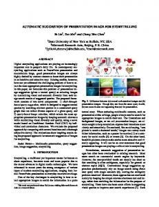
Figure 1. Collaboration of Travel service
sd SendScheduler sd OrderFlightTicket TA TA
If the order fails, travel agent will apologize to the user, otherwise flight company will send the information about the ticket to travel agent and give the ticket to the user. Then travel agent will generate the scheduler according to the information and then send the scheduler to user.
User
Flight
SendScheduler
orderTicket
alt
Name: Travel Roles: User, TA, User, Bank Interaction:
success
sd Travel
fail
Name: SendFightTicket Roles: SFTUser, SFTFlight Interaction:
2.2. Method overview
ref
ApplyTravelPlan
sd SendFightTicket Valid
The method contains seven steps: (1)Identify concept level roles: Identify concept level roles system participates according to the informal requirements of the system. (2)Define service: Use UML 2.0 Collaboration maps to define the basic services of two roles, and step by step get the composition service of the whole system; (3)Define interaction: Use UML 2.0 Sequence Diagram(SD) to define interaction of each basic service, and use UML 2.0 Interaction Overview(IO) to define the composition services; (4)Synthesize role automaton: Apply scenarios-based synthesis technique to synthesize role behavior model of each service; (5)Model checking: Verify desired properties of the role by model checking; (6)Synthesize component automaton: Identify the services a component participated, then synthesize the component automaton according to the synthesized role automata and relations among these role automata; (7)Compositional reasoning: Use compositional reasoning to verify liveness properties of the component.
Flight
User sendTicket
success ref CheckCreditCard invalid
Name: ErrorInformation Roles: EITA , EIUser Interaction:
ref
ErrorInformation
sd ErrorInformation TA
User
ref
OrderFightTicket
invaildBank fail
ref
Name: Apology Roles: ATA , AUser Interaction:
success par ref
sd Apology Flight
Apology
SendFightTicket
User ref
flightNotAvailable
SendScheduler
Figure 2. Service specification based on UML 2.0 SD
2.3. Service specification based on collaboration
Name: OrderFlightTicketTA Automaton:
Name: ApplyTravelPlanTA Automaton:
?success
!orderTicket
!success ?applyTravel
?fail
Step 1: Identify concept level roles: According to the informal requirements of the running example, we conclude that there are four concept level roles in the system: User, TraveAgency(TA), Bank and Flight. Step 2: Define service: We can use UML collaboration maps to define the services these four roles participate until the service of the whole system. Fig. 1 gives the seven basic services which are collaborations of two roles and the composition service of these seven basic services, the detailed interaction of each service will be explained in step 3. Step 3: Define interaction:
!fail Name: SendSchedulerTA Automaton:
Name: CheckCreditCardTA Automaton:
?valid
!verifyCredit
!sendScheduler
?invalid Name: ApologyTA Automaton:
Name:ErrorInformationTA Automaton: !invalidBank
!flightNotAvailable
Figure 3. Automaton of role TA from simple service specification
512
Definition 1 (Service): Service is a triple: Service = (N ame, R, I), where N ame is the name of service; R = {r1 , r2 , ..., rn } is the set of roles which participate in the service, and these roles are service level roles, i.e. a concept level role participates into different services, and acts as different service level roles; I is a set of UML 2.0 SD or UML 2.0 IO describing the service interaction. Service is divided into basic service and compositional service. Basic service is composed of collaboration of two roles. The definition of basic service can be extended as: Service = (N ame, {ri , rr }, sd), where ri is the invoked role and rr is the received role. sd describes the interaction of the services, and usually is a UML 2.0 SD. Compositional service is composed of two or more basic services, and it can be composed of two or more roles. Thus SD = {sd1 , sd2 , ..., sdm , io} has m UML 2.0 SDs and a UML 2.0 IO which is used to represent the relations among these basic services.
Definition 4 (Role Synthesis) The function of a role in a service is described by the role automaton. Role synthesis is to automatically get the automaton which satisfies the function.
Fig. 2 shows service specification of the running example which has seven basic services as AT P , CCC, OF T , SS, SF T , EI, A and a compositional service T ravel which is composed of these basic services. Step 4 and 5: Synthesize role automaton and model checking:
Considering the role AT PT A in service AT P , its liveness can be represented by CTL formulas as EF applied and EF failed. EF applied represents that there is a state in the automaton satisfying applied, where applied means the role AT PUser applies successfully. EF failed represents that there is a state in the automaton satisfying failed, where failed means the AT PUser applies unsuccessfully. Safety of role AT PT A can be defined as AG ¬(applied ∧ failed), which means there is no state in the automaton satisfying both applies successfully and unsuccessfully. Therefore, the verification of role AT PT A can be represented as: MT A |= EF applied ∧ EF failed ∧ AG ¬ (applied ∧ failed). Software evolution is inevitable, and our method must support it. For a role, we consider it has two kinds of changes: firstly, when requirement argues new behaviors, this means Role Extension which adds new behaviors into the original role; secondly, when requirement needs to reduce some original behaviors, this means Role Reduction which reduces behaviors of the original role.
The synthesized algorithm of role behavior in basic services is very simple. According to the service specification, the role automaton of TA in service AT P , CCC, OF , SS, and EI is showed in Fig. 3. Definition 5 (Role Verification) Role verification is to decide whether M |= Ψ holds when a Role = (N ame, M, Ψ) is given. We use the traditional model checking method to verify. Due to not too large state space of simple role, this method does not suffer from state space explosion problem.
Definition 2 (Automaton) An automaton is a 5-tuple M = (S, Σ, T, q0 , F ), where S is finite states set, Σ is the alphabet of automaton, T is the translation relations as a triple T ⊆ S × Σ × S, q0 is the initial state and F is the final state set. There is a sequence of states s1 , s2 , ..., where for all i ≥ 1, ∃a ∈ Σ, such as (si , a, si+1 ) ∈ T , and ∀s ∈ S, exists a sequence: s1 , s2 , ..., sn , such as s1 = q0 and sn = s. A property set on an automaton is denoted as Ψ. When ψ ∈ Ψ is satisfied in a state s ∈ S, we can denote as s |= ψ. Definition 3 (Role) A role is a triple r = (N ame, M, Ψ), where N ame is the name of role, M is the behavior automaton of the role as defined above which can be synthesized from UML 2.0 SDs. Ψ is the property set the role must satisfy when collaborating. Normally, we can divide properties into safety and liveness, i.e. Ψ = {Ψs , Ψl } where Ψs represents safety while Ψl represents liveness. If we denote r as a role, safety can be defined as: ∀ψ ∈ r.Ψs , ∀s ∈ r.M.S, such as s |= ¬ψ holds; liveness can be defined as: ∀ψ ∈ r.Ψl , ∃s ∈ r.M.S, such as s |= ψ holds. Thus we can say that safety must be avoided in every state while liveness must be satisfied in some states.
Definition 6 (Role Extension and Reduction) A role r1 is a reduction of another role r2 , if and only if the behavior automaton of r1 i.e. r1 .M and the behavior automaton of r2 i.e. r2 .M have the following relations: r1 .M.Σ ⊆ r2 .M.Σ; r1 .M.S ⊆ r2 .M.S; r1 .M.s0 = r2 .M.s0 ; r1 .M.T ⊆ r2 .M.T and r1 .M.F ⊆ r2 .M.F . On the contrary, role r2 is an extension of r1 . Theorem 1 The liveness property set of r2 is denoted as Ψl . If r1 is an extension of r2 and r2 |= Ψl holds, r1 |= Ψl holds. On the contrary, if safety property set of r1 is denoted as Ψs and r1 |= ¬Ψs holds, r2 |= ¬Ψs holds.
513
Name: OrderFlightTicket1 TA
Flight
Name: OrderFlightTicket2 TA
orderTicket
success
Flight orderTicket
Name: OrderFlightTicket1TA Automaton: !orderTicket
!fail
?success
?applyTravel
Par success
fail
Name: OrderFlightTicket2TA Automaton: !orderTicket
!success
!verifyCredit ?invalid
?success ?fail
waiting
!sendScheduler
?waiting
?success
!orderTicket
?valid !invalidBank
?fail !flightNotAvailable
Figure 4. Extension and reduction of roles TA of service OrderFlightTicket
Figure 5. The automaton model of component TA
Proof: If r2 |= Ψl holds, according to the definition of liveness, ∃s ∈ r2 .M.S such as s |= Ψl . Because role r1 is an extension of r2 , according to the definition of role extension, r1 .M.S ⊇ r2 .M.S. Therefore, ∃s ∈ r1 .M.S, such as s |= Ψl , then r1 |= Ψl . On the contrary, if r1 |= ¬Ψs , according to the definition of safety, ∀s ∈ r1 .M.S, such as s |= ¬Ψs . Because r2 is a reduction of r1 , according to the role reduction definition, r2 .M.S ⊆ r1 .M.S. Therefore, ∀s ∈ r2 .M.S, such as s |= ¬Ψs , then r1 |= Ψs .
name of the component; R = {r1 , r2 , ..., rn } is the role set a component contains; M c = C(r1 .M, r2 .M, ..., rn .M ) means the corresponding behavior automaton which is composed of its role automata and the relations describing them. Ψc = {Ψ1 , Ψ2 , ..., Ψn , Ψc }, where Ψ1 , Ψ2 , ..., Ψn are the corresponding property sets of each role r1 , r2 , ..., rn . Ψc is the liveness property set component behavior automaton must satisfy when composing component’s role automata.
For example, there exists two kinds of requirement evolution in service OF T : one is that role OF TT A must guarantee that the OF T service must be successful. Therefore, the order will always succeed in the service specification, which means role OF TT A will reduce the unsuccessful behaviors; the other is that the Flight may be busy when ordering. The OF T service will add new behaviors to deal with this condition, which means role OF TT A must be extended. Fig. 4 shows the scenarios and the corresponding automata of two kinds of modifications. Role OF T 1T A in service OF T 1 is a reduction of role OF TT A in service OF T . According to Theorem 1, the safety property AG (ordered ∧ failed) will still hold in the new role, however, the liveness properties in the original roles may not be satisfied, and they need to reverify. For example, original liveness property EF failed will not hold in the new role. On the contrary, role OF T 2T A in service OF T 2 is an extension of role OF TT A in service OF T . According to Theorem 1, liveness properties in the original role EF ordered and EF failed will still hold, and the safety property AG (ordered ∧ failed) will still hold in the new role, however, there may exist such safety properties which do not exist in new role. For instance, the original role has no deadlock, but the new role may have deadlock because of adding new behaviors.
Definition 8 (Component Synthesis) Component synthesis is to automatically synthesize the behavior automaton of the component according to the its role automata and the relations describing these automata. The essential condition of component synthesis is to identify the relations among its roles. Because the basic service is defined by the collaboration of two roles. We can define the relations of roles a component participated as sequence, loop, alterative and parallel. Assuming r1 and r2 are two roles of a component C, we can define the relations between r1 and r2 as follows: Sequence: Sequence relation means the behavior of role r1 is followed by the behavior of role r2 , The behavior automaton of the component can be denoted as r1 · r2 . Then C.M = r1 .M · r2 .M . The detailed algorithm is showed as algorithm 1. The property relations of role r1 and 2 can also be defined as rule Rseq : ∃ψ1 ∈ r1 .Ψl , ∀ψ ∈ r2 .Ψl , such as ψ1 → EF ψ. Alternative: Alternative relation means the component behavior will choose one of the roles r1 or r2 to implement, denoted as r1 |r2 . The behavior automaton of the component can be denoted as C.M = r1 .M |r2 .M . The detailed algorithm is showed as algorithm 2. We can also define the property relations of them as rule Ralt : Ralt : ∀ ψ1 ∈ r1 .Ψl , ∀ ψ2 ∈ r2 .Ψ2 , (ψ1 → AG ¬ ψ2 ) ∨ (ψ2 → AG ¬ ψ1 ). Loop: Loop means that a component always acts as role r1 until certain condition holds. The detailed algorithm is showed as algorithm 3. We can define the property relations
2.4. From service specification to component specification Step 5 Synthesize component automaton: Definition 7 (Component) A component is a 4-tuple, Component = (N ame, R, M c , Ψc ), where N ame is the
514
the properties of these roles can be verified as follows: (1)AT PT A|= EF applied ∧ EF failed ∧ AG (applied ∧ failed); (2)CCCT A |= EF valid ∧ EF invalid ∧ AG (valid ∧ invalid); (3)OF TT A |= EF ordered ∧ EF failed ∧ AG (ordered ∧ failed); (4)SST A|= EF sent; (5)EIT A |= EF error; (6)AT A |= EF apologized; We can define some liveness properties of the component TA as follows: ψ1 = EF(((applied → EF valid) → EF ordered) → EF sent) means when the user has successfully applied the plan, there exists a way that credit card is valid, and there exits a way ticket is successfully ordered, and then there exist a way scheduler will be sent to the user. ψ2 = AG ((sent → AG ¬ apologized) ∨ apologized → ¬ sent)) means either TA will apologize to the user or the scheduler will be sent to the user. ψ3 = AG ((ordering → AG ¬ error ∨ error → AG ¬ ordering) means either TA will order the ticket or TA will inform the user that credit card is invalid. These liveness properties can be proved as follows: Proof: (7) applied → EF valid
of them as rule Rloop : Rloop : ∀ψ ∈ r1 .Ψl , (ψ → EF ψ)U φ. Parallel: Parallel means role r1 and r2 can be implemented in any order, denoted as r1 ||r2 . The behavior automaton of the component can be denoted as C.M = r1 .M ||r2 .M . The algorithm of Parallel is very complex, we will consider it as next work. We define the property relations as rule Rpar : Rpar : ∃ ψ1 ∈ r1 .Ψl , ∃ ψ2 ∈ r2 .Ψl , (ψ1 → EF ψ2 ) ∨ (ψ2 → EF ψ1 ) ∨ (ψ1 ∧ ψ2). For example, component T A participates into services AT P , CCC, P F T , SS, A and EI, we can synthesize the behavior automaton in Fig. 5 according to the UML 2.0 IO in Fig. 2 and algorithm 1-3. Step 6: Compositional reasoning: Definition 9 (Component Verification) Component verification is to verify whether M c |= Ψc holds when a component C = (N ame, R, M c, Ψc ) is given. The traditional component verification method is based on model checking, and when the state space of component is too large, the method may suffer from ”state space explosion” problem. Therefore, we can firstly verify each role by model checking, i.e. r1 .M |= Ψ1 , r2 .M |= Ψ2 , ..., rn .M |= Ψn , then use compositional reasoning to verify the component which satisfies the desired liveness properties, i.e. M c |= Ψc . In the end, we conclude that M c |= Ψc which is assured by Theorem 2.
Rseq ,(1),(2) (8)(applied → EF valid) → EF ordered Rseq ,(3),(8) (9) (((applied → EF valid)→ EF ordered) → EF sent Rseq ,(4),(9) Therefore EF(((applied → EF valid) → EF ordered) → EF sent), thus ψ1 holds (10)AG (sent → AG ¬ apologized ∨ apologized → AG ¬ sent)
Theorem 2 Given a component C = (N ame, R, M c, Ψc ), if r1 .M |=, r2 .M |= Ψ2 , ..., rn .M |= Ψn holds, and the component is composed of its roles through sequence, loop, alternative and parallel. We can conclude that M c |= Ψc . Proof: Because r1 .M |= Ψ1 , r2 .M |= Ψ2 , ..., rn |= Ψn holds and the component is composed through sequence, loop, alternative and parallel. We can apply rules Rseq , Rseq , Rloop , Rpar to conclude M |= Ψc r .M|=Ψ1 ,r2 .M|=Ψ2 ,...,rn .M|=Ψn ,Rseq ,Ralt ,Rloop ,Rpar i.e. 1 M c |=Ψc Therefore, M c |= Ψc holds and the component behavior automaton has been verified.
Ralt , (4), (6) (11)AG (ordering → AG ¬ error ∨ error → AG ¬ ordering) Ralt , (3), (5) Therefore, ψ2 and ψ3 hold.
3. Related work Using the idea of role to develop software is not a new idea. Sanders et al. proposed a method to hierarchically design real-time distributed system pattern based on role, and then model check each pattern. Based on the pattern designed, the method designed and verified component and system behavior model[7]. In [6], the author
For example, component T A involves in six services such as AT P , CCC, OF T , SS, EI and A, and acts as six roles,
515
of component; secondly, if our method verifies each property against each role automaton, this would involve a combinatorial number of verifications with an effect similar to the state explosion problem when components are verified. Therefore, we ought to select some critical and important properties to verify thus avoid this problem. Next we plan to use the method to support new merits of service such as service discovery, automatic service composition and component interface substitution. We also plan to develop a tool for the method.
extended original method, and combined scenarios-based synthesis techniques to automatically synthesize behavior model of simple pattern, and proposed a method to detect and resolve inconsistency of multi-scenarios. Our method absorbs some of these ideas, however, we use them in service-oriented environment. Kruger et al. [8] proposed a service-oriented method to develop service-oriented architecture. The method firstly defined service specification of the system based on MSC(Message Sequence Charts), then automatically translated service specification into component specification. These ideas are similar to our method, moreover, our method verify properties of roles and components. In [11] Goal Sequence Diagram (GSD) was proposed to model pear to pear service type, and the method also viewed service as the collaboration of different roles. In [12, 13], the author specifically used UML collaboration maps to research service specification and service composition, and defined semantic interface of component to support service discovery and component reuse. GSD was also used in [4, 5] to detect and resolve implied scenarios. GSD just considers liveness properties. Our method can verify liveness and safety properties on simple role, but it can only verify liveness properties of component. In [3], a new synthesis method was proposed based on Use Case Map. Although UCM has the powerful expression of overlapped scenarios, the algorithm is too complex and hard to design correctly. Our method uses basic services of two role collaboration which can avoid overlapped scenarios problems when composing services, and uses UML 2.0 IO to describe service composition, thus reduces design complex of synthesis algorithm. Another work related to this paper is compositional verification[1, 7]. Traditional compositional verification firstly verifies component by means of model checking, then uses compositional methods to verify the composed architecture based on these different components. These methods include assume-guarantee[2], theorem proving[1] and compositional reasoning[7]. They can reduce state space explosion problem to some extent. However, when the state space of simple component is too large, it is still facing the same problem when the component state space is searched. In theory, our method verifies simple component based on compositional reasoning and is more fine-grain than traditional methods, which is more efficient to solve the state space explosion of simple component than traditional methods.
References [1] S. Berezin. Model checking and Theorem proving. PhD thesis, Carnegic Mellon University, Pittsburgh, 2002. [2] M. Caporuscio, P. Inverardi, and P. Pelliccione. Compositional verification of middleware-based software architecture descriptions. In Proc of. 26th International Conference on Software Engineering, pages 221–230, 2004. [3] H. Castejon. Synthesizing state-machine behavior from uml collaborations and use case maps. Lecture Notes in Computer Science, 3530:339–359, January 2005. [4] H. Castejon and R. Brak. A collaboration-based approach to service specification and detection of implied scenarios. In proc. of 6th SCESM, pages 37–43, 2006. [5] H. Castejon and R. Brak. Formalizing collaboration goal sequences for service choreography. Lecture Notes in Computer Science, 4229:275–291, 2006. [6] H. Giese, F. Klein, and S. Burmester. Pattern synthesis from multiple scenarios for parameterized real-time uml models. Lecture Notes in Computer Science, 3466:193–211, 2005. [7] H. Giese, M. Tichy, S. Burmester, and W. S. S. Flake. Towards the compositional verification of real-time uml designs1. In Proc. of 9th European software engineering conference held jointly with 11th ACM SIGSOFT international symposium on Foundations of software engineering, pages 38–47, 2003. [8] I. Kruger and R. Mathew. Component synthesis from service specification. Lecture Notes in Computer Science, 3466:255–277, 2005. [9] OASIS. Universal Description Discovery and Integration (UDDI) Version 3.02, 2005. [10] Object Management Group (OMG). UML 2.0 superstructure, 2005. [11] R. Sanders and R. Brak. Modeling peer-to-peer service goals in uml. In proc. of 2nd international conference on software engineering and formal methods, pages 144–153, 2004. [12] R. Sanders, R. Brak, G. Bochmann, and D. Amyot. Service discovery and component reuse with semantic interfaces. Lecture Notes in Computer Science, 3530:85–102, 2005. [13] R. Sanders, H. Castejon, F. Kramer, and R. Brak. Using uml 2.0 collaborations for compositional service specification. Lecture Notes in Computer Science, 3713:460–475, 2005. [14] World Wide Web Consortium. Web Services Description Language (WSDL) 1.1, 2001.
4. Conclusions This paper proposes a service-oriented method to systematically design component behavior model of distributed system, and presents a different method to verify liveness properties of component. Our method still has some defects. Firstly, our method just focuses on liveness properties
516