A running-wheel movement-detection method is described for use with a modified 1350 Commo- ... wheel support frame, so that the rubber ball of the mouse.
Behavior Research Methods. Instruments. & Computers 1992. 24 (3), 412-413
A simple and sensitive method for monitoring running-wheel movement ALLEN D. PETREE, NABIL F. HADDAD, and LAURENCE H. BERGER University of Montana, Missoula, Montana A running-wheel movement-detection method is described for use with a modified 1350 Commodore mouse and a Commodore 64, is described. The movement-detection method allows for the detection of partial revolutions and direction of movement, but requires no interface equipment. The modified running wheel is discussed as a new technique that may be useful for bridging empirical and theoretical differences between free-operant and discrete-trial runway procedures.
In recent years, the use of microcomputers in operant behavior laboratories has increased dramatically. By using simple relay and switch closure technologies, microcomputers have been easily adapted to tasks that involve ieverpressing, keypecking, pellet dispensing, and the initiation of stimulus events. However, designing and implementing a computer method for tasks with the running wheel has been considerably more difficult because of the complexity of monitoring wheel movement. The traditional running wheel is equipped with a mechanical counter or an electrical switch that is capable of monitoring only full wheel rotations. Since partial rotations and direction changes have been observed (Schick, 1979, cited in Porter, Furber, & Geise, 1982), such a gross level of measurement is clearly insufficient for operant research designs. Hence, very few operant studies of running wheels have been conducted successfully. As a solution to the measurement problem, Porter, Furber, and Geise (1982) described a running-wheel tachometer in which wheel movement was detected when wires, inserted in a rubber cork attached to the wheel axle, moved through a photobeam of a photo-coupled interrupter module. The output from the photo-coupled interrupter was routed through a pulse-forming circuit interface and read as interruption signals by a computer. The sensitivity of movement detection was increased or decreased by increasing or decreasing the number of wires inserted into the rubber cork, respectively. While this technique is sufficient to detect partial revolutions, it requires a pulse-forming circuit interface to send the interruption signals to a computer, and it is incapable of differentiating movement direction. The present paper describes a wheel-movement detection method whereby a modified computer mouse can detect partial revolutions and changes in direction; no interface equipment is required.
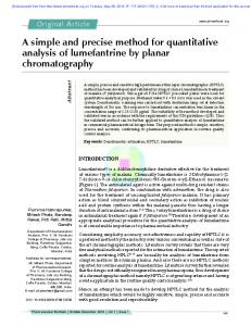
Apparatus A modified 1350 Commodore mouse is used to detect wheel movement from a 36-cm-diam Wah mann running wheel, with a Commodore 64 as the controlling microcomputer. The mouse is mounted in an inverted position on the bottom of the support plate that is attached to the top of the wheel support frame. The cover of the mouse has been removed to allow access to the photo-interrupter units (see Figure 1). Due to the differences in size between the axles of the wheel and the mouse photo-interrupter unit, a reduction system was necessary to disallow photointerrupter axle rotation speeds that could exceed the measurement capabilities of the mouse electronics. The sim-
Correspondenceregarding this article may be sent to A. Petree, Department of Psychology, University of Montana, Missoula, MT 59812.
F"JgUI'e 1. Running-wheel modificatiom for monitoring wheel movement with the use of a 1350 Commodore mouse.
Copyright 1992 Psychonornic Society, Inc.
412
Photo_/ Interupter module
IMouse .....•....
18.25 em!
..
110.16 em
1--I
~ I--
support frame
I
1-11350
Fiber
belt
I
I
mouse I
I
Pulley reduction system
I
I-I G-rlng I
/ Running wheel support frame
............
I Running
wheel
axle
I
~
AUTOMATED RUNNING WHEEL plest reduction technique would be to slip a metal drum over the wheel axle and attach the 1350 mouse to the wheel support frame, so that the rubber ball of the mouse could rest on the metal drum. Because of other hardware mounted on the wheel support frame and axle, however, a metal drum could not be fitted, and a pulley reduction system was designed instead. The pulley reduction system, composed of two Plexiglas pulleys (7.0 em and 0.64 em outer diameter [Off], respectively), reduced the output from the wheel by a factor of 11. An a-ring was attached to the O.64-cm-OD wheel axle and the 7.0-cmOl) pulley, and a fiber belt was attached to the O.64-cmOl) pulley wheel and the O.64-cm-OD mouse axle. The fiber belt, O.64x 18.0 em, was made from commercial iron-on patch material with the ends adhered together through the application of heat. Signals from the mouse were conducted through the mouse cord, which can be attached directly to either serial port on the Commodore 64 computer. The parameters of the pulley reduction system allow for 36 photobeam interruptions per wheel rotation (3.1 em/interruption). For many applications, the Commodore's resident BASIC may be sufficient for programming purposes. However, resident BASIC in the Commodore is not sufficient to produce real-time applications for operant applications using the running wheel, and a structured assembly language such as PROMAL, PASCAL, or C is necessary to fulfill the real-time requirements. PROMAL was used with the present apparatus. The routine to scan the joyport memory area is shown in appended listing. Discussion The measurement system described above extends beyond the capabilities of previously described systems, be-
413
cause it allows for differentiation of movement direction and requires no interface equipment. In addition, the sensitivity of the measurement system may be changed by increasing or decreasing the pulley reduction factor, which allows the experimenter to modify the apparatus to suit specific experimental designs. Over the past 3 years in our laboratories, this measurement system has been used in conjunction with a Rayfield card interfaced with multiple optically isolated relay circuits (Rayfield & Carney, 1981), to drive peripheral devices such as pellet dispensers, stimulus lights, stimulus sounds, and a solenoid braking system. This braking system prevents wheel movement, such as that during an intertrial interval. Although the present measurement system establishes a more useful automation of the running wheel, still more important is that it creates a new method of investigation. The automated running wheel could become a common method, useful for bridging empirical, and perhaps even theoretical, differences between free-operant and discretetrial runway procedures, such as behavioral and incentive contrast. Also, with the addition of a resistance device, the running wheel is ideal for directly examining the effects of response cost on schedules of reinforcement that are defined as a function of the amount of effort required by the subject to respond.
REFERENCES PORTER, J. J., FURBER, A. M., &: GEISE, E. G. (1982). A running wheel tachometer. BehaviorResearch Methads & Instrumenuuion, 14, 52-53. RAYFIELD, F., &: CARNEY, J. (1981). Controlling behavior experiments with BASICon 6502-based microcomputers. BehaviorResearch Methods & Instrumentation, 13, 735-740.
LISTING PROMAL Routine for Scanning Running Wheel Movement For J = 1 to 50 Content = GAMEPORT2 ;Check byte value -$DCOO For I = 0 to 1 ;Check bit values Bit = Content % 2 ;Odd or Even? If Bit = 0 ;If photo-interrupt Count[I] = Count[l] + 1 ;Increment counter ;Count[O] = Direction 1 ;Count[l] = Direction 2 Content = Content > > 1 ;Shift to next bit
(Manuscript received August 5, 1991; revision accepted for publication February 19, 1992.)