A SIMPLE COMPUTER PROGRAM FOR TEACHING THE TRANSIENTS OF THE SYNCHRONOUS MACHINE G. D. Marques Secção de Máquinas Eléctricas e de Electrónica de Potência Instituto Superior Técnico, Av. Rovisco Pais, 1096 Lisboa Codex, PORTUGAL FAX: 351 - 1 - 841 71 67; email:
[email protected]
Abstract: The synchronous machine with damper windings is modelled with a minimum of six order nonlinear differential equations. As the equations are of high order, the traditional methods used to teach this subject are difficult, boring and inefficient leading to use a great effort and to spend a considerable amount of time. To solve this problem, a computer simulation for teaching and learning on the dynamics of the synchronous machine has been developed for undergraduate students. The method was designed in a way that leads to a easy understanding of the synchronous machine model as well as to obtain easily the transient response in constant or in variable speed. The response of the students to this new method is very satisfactory.
1.- INTRODUCTION Technologies are opening new opportunities for the realisation of innovative learning environments that break the time and space barriers of traditional methods. A great improvement can be obtained in the teaching of electrical machines where there are some subjects difficult to teach and there are less time to use. Although it is widely accepted that the dynamic behaviour of electric machines should be introduced to the undergraduate students, it suffers from the problem that undergraduate electric machines curriculum involve substantial mathematics. As a result, some other basic contents may be sacrificed. The study of this machine in transient regime is usually done in two different conditions: electric transients where the condition of constant speed (5 linear differential equations) is assumed and electro-mechanical transients that are concerned with time-dependent variations of rotor angle and electrical power [1] to [5]. The methods more generally used, method of partitioning and method of operational impedances, involve substantial mathematics leading to spend a considerable amount of time and effort. These methods are also boring leading to the students detachment. Due to large number of short-circuit coils, the method of partitioning is especially used for the analysis of transient and asymmetrical operation of synchronous
machines. Partitioning is the process of resolving a matrix into submatrices, thus converting it to a hypermatrix. By the elimination of some parts, the order of the matrix can be reduced. This method involves considerably mathematics, but is largely used. In the method of operational impedances, the currents in the field and damper windings are not required and are eliminated taking Laplace transforms and defining transfer functions. This paper presents a computer program that was developed to use in the teaching of the synchronous machine dynamics. Thus, is my intention that students should be able to learn the dynamic behaviour of the synchronous machine without going through complicated mathematics. The computer program has been designed as a complementary tool for the teaching of the synchronous machine dynamics but could be used for student laboratory. It is supposed to work both as a teaching aid and a learning tool. The approach used leads to simple equations and simple diagrams. To solve the differential equations the MatLab/Simulink environment is used. MatLab is a well-known software package for computer simulation that is also commonly used for teaching and learning in undergraduate courses. It is also efficient in the simulation of power electronic circuits [6]. It consists of a series of standard routines and software toolboxes,
which enable the students to perform the simulation efficiently without a great effort. The simulink has also the advantage of a graphical interface that uses block diagrams. Block diagrams can also help on the understanding of the synchronous machine model. Time-domain simulation of the synchronous machine is an important tool to access its dynamic behaviour. During the simulation, observing the current, fluxes and torque waveforms can provide an insight that is not always possible with pencil and paper analysis. As will be shown in the paper the xy plot is also an important tool for the understanding of the synchronous machine dynamics.
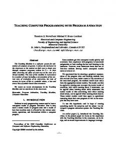
2.- SYNCHRONOUS MACHINE MODELING The traditional model of the synchronous machine is used in this computer program. This model is obtained considering the machine as 6 magnetically coupled circuits. Figure 1 shows a representation of the synchronous machine where no damper circuits are represented. To eliminate the redundancy of the three-phase windings, substituting these by their two-axis equivalents, the phase transformation is used. This reduces a three-phase winding to a set of two phasewindings having their magnetic axes arranged in quadrature. 2
4
θ 1
3 Fig. 1: Synchronous Machine Representation.
This transformation is the so called αβ transformation and is also called in the literature as the Clarke’s or Concordia’s transformation and its corresponding matrix
is:
x1 x2 = x3
1 2 1 − 3 2 1 − 2
0 3 2 3 − 2
1 2 x α 1 xβ 2 x 1 0 2
(1)
Where x denotes general variables that can be currents, voltages or linkage fluxes. The x1, x2 and x3 variables are the system variables while xα, xβ and x0 are the transformed variables. The transformed zero current component is null when no neutral point is used. As this is the case in the majority of the applications, the treatment of the model is often done with only the αβ components. To simplify the equations, a new transformation is normally used as a second step. The two poliphase windings are viewed in a common reference frame, the dq reference frame. In the synchronous machine the rotor reference frame is used. It is possible to show that this reference frame is the only one that simplifies the equations when rotor saliency is present. The transformation is given by: xα xβ
cosγ = sin γ
− sin γ xd cos γ x q
(2)
Where γ is the transformation angle. This transformation is now a time variant transformation because γ is normally a time varying function. For synchronous machine, in per unit notation with the time in seconds, where γ=θ, equations (3) and (4) are obtained. u d = rs id +
1 d ψd − ωψq ωb dt
(3.a)
u q = rsiq +
1 dψq + ωψd ωb dt
(3.b)
1 dψ f ωb dt
(3.c)
0 = rDi D +
1 dψD ωb dt
(3.d)
0 = rQiQ +
1 dψQ ωb dt
(3.e)
u f = rf i f +
The inductance matrices are: ψd Ld ψ = M f df ψD M dD
ψq ψ = Q
M df Lf M fD
Lq M q
M dD id M fD i f LD iD
(4.a)
M q i q LQ i Q
(4.b)
The DQ model of the synchronous machine is represented with three sub-blocks and the representation of (3) and (6). The “Momento” block determines the electromagnetic torque, (5), and the block “Linv-d” computes the three d-axis currents using the three linkage fluxes and the inverse Ld inductance matrix. The block “Linv-q” computes the q-axis currents. These blocks are represented in (fig. 4), (fig. 5) and (fig. 6).
The electromagnetic torque is given by:
rf
Mem = ψ dsiqs −ψ qsids
(5)
-Krs
6 if
1/s Yf
2 id
1 ud
+ + Sum
-Kwb2
1 Mem
1/s Yd
+ -KS u m 3 1/2H
Momento
* P1 * P2
(6)
4 Mc
-Krs_ 2 uq
3.- BLOCK DIAGRAM OF THE SYNCHRONOUS MACHINE
-K+ Sum2 wb
Linv-d
and the motion is described by: dωm J = M em − M c dt
rf
3 uf
-K+ Sum1 w b 1
1/s Yq
5 wm_
-Kwb3
3 iq
Linv-q
1/s wm
4 teta
1/s Int1
Fig. 3: DQ representation of the synchronous machine.
The model of the synchronous machine in dq variables is represented by (3), (4), (5) and (6). Currents or linkage fluxes can be used as state variables. Traditionally, the currents are used as state variables. In the computer program described in this paper, the linkage fluxes are chosen as state variables because this leads to a major transparent model and it was verified with the comparison with other models that this leads to faster calculations. The MatLab/Simulink environment was used leading to a model written in block diagrams.
2 Yd 1 Yf
Mux
K
Demux
Mux
Ldinv
Demux
1/s YD
1
2 id
Yq Mux
1 if
Mux
1 iq
Demux
Lqinv -K-
1/s
-K-wb rD
Demux
K
Yq1 -wb rq1
Fig. 4: Linv-d block and Linv-q. 1
*
Id
4
Product
+ Sum
Yq 2
*
Iq
3
1
1 p
Mem
Product1
Yd
Fig. 5: “Momento” block. Ud
Mem
1
id
2
tri-fonte
ia
abcDQ
b 3
DQabc1
uf
c
Sín-comp
wm
Mc
+ Sum1
a + + Sum + Sum2
-K-
-Ksqrt(2/3)
1/2
f(u)
1
Fcn
d
f(u)
2
Fcn1
q
Mux -K-
Mux
1/sqrt(2)
4 ângulo
if
Fig. 6: Transformation abc-dq.
Fig. 2: Block diagram of the synchronous machine.
Figure 2 shows the general block diagram that represents the above equations. The “abcDQ” and “DQabc1” blocks realise the transformations of variables defined by (1) and (2). The block “Sin-comp” represents the synchronous machine in dq variables in the rotor reference frame. This block is described in (fig. 3).
4.- EXAMPLES OF APPLICATION
To illustrate the possibilities of the program, two wellknown transients are simulated and presented in the next
subsections. The first group of results refers to the threephase symmetrical short-circuit. The second group of results refers to the application of mechanical load to the synchronous motor. In this second transient a step of load torque is applied to the shaft of the motor.
5.5 5 4.5 4 if [p u ]
3.5 3 2.5 2
4.1.- Three-phase short-circuit transient
1.5 1
The behaviour of the synchronous machine to a threephase short circuit is presented in the next figures.
0
5
10
15
time [s]
Fig. 9: Field current. 2
0
5 4
id [ pu]
-2
3 i D [p u ]
-4
-6
2 1
-8 0 -10
0
5
10
-1
15
time [s] -2 0
Fig. 7: Direct current.
0.5
1
1.5 Time [s]
2
2.5
3
Fig.10: Direct damper current.
5 4 4
3 2
3 2
0 -1
1 iQ [p u ]
-2 -3 -4 -5
0 -1
0
1
2
3
4
5
-2
time [s] -3
Fig.8: Quadrature current. -4 0
0.5
1
1.5 Time [s]
2
2.5
Fig. 11: Quadrature damper current. 8 6 4 ic [pu]
iq [ pu]
1
2 0 -2 -4
0
0.5
1
1.5
2
time [pu]
Fig.12: Phase current during the transient.
2.5
3
3
1 0.8 0.6 0.4
ψ q [pu]
The direct and quadrature stator currents are presented in (fig. 7 and 8). Phase c stator current is presented in (fig. 12). In this figure it is clear the subtransient and transient periods. Figures 9, 10 and 11 show the field current, the direct and the quadrature damper currents. These figures have different scales to illustrate the different periods. Figure 13 presents the torque of the machine. XY plots of the stator currents and fluxes are presented in (fig. 14 and 15). These figures are a precious tool for the understanding of the transient.
0.2 0 -0.2 -0.4 -0.6 -0.8 -1 -1
-0.5
0
0.5
1
ψ d [pu] 5
Fig. 15: XY plot of the dq fluxes
4 3 1.5
Mem [pu]
2 1
1 0 -1
0.5 ia [pu]
-2 -3
0
-4 -0.5 -5 0
1
2
3 time [s]
4
5
6 -1
Fig. 13: Torque.
-1.5
0
1
2
3
4
5
4
5
Time [s]
4
Fig. 16: Stator current. 2
2.1
-2
2
iβ
[pu]
0
1.9
-4
1.8 if [pu]
-6 -8 -10 -5
1.7 1.6
0
5
iα [pu] Fig. 14: XY plot of the αβ currents.
1.5 1.4 1.3
0
1
2
3 Time [s]
4.2 Aplication of a torque on the shaft In the second transient, the application of a step of torque in the shaft is presented. Figure 16 presents the stator currents. The typical low-frequency oscillation of the synchronous machine is clearly visible.
Fig. 17: Field current.
This oscillation is also visible in (fig. 17 to 19) where the waveforms of the currents in the Park’s reference frame are presented. It is also presented on the torque, (fig. 20).
2
0.1 0
1.5
-0.1 1 -0.2 0.5
iβ [pu]
id [pu]
-0.3 -0.4 -0.5
0 -0.5
-0.6 -1 -0.7 -1.5
-0.8 -0.9
0
1
2
3
4
-2 -2
5
-1.5
-1
-0.5
0
0.5
1
1.5
2
Time [s]
iα [pu] Fig. 18: Stator direct currrent. Fig. 21: XY plot of the αβ currents 1.6 1.4
5.- CONCLUSION
1.2
iq [pu]
1
A comprehensive tool for the teaching and learning of the synchronous machine dynamics was developed. The computer program uses linkage fluxes as state variables. This leads to a simple and efficient model. Block diagrams were used to represent the machine. The model is integrated using the MATLAB/Simulink environment. This tool was used to teach leading to excellent results.
0.8 0.6 0.4 0.2 0 -0.2
0
1
2
3
4
5
Time [s]
Acknowledgement: Part of the costs related with the publication of this paper was supported by CAUTL.
Fig. 19: Stator quadrature current.
References
1.8 1.6
[1] G. J. Retter, “Matrix and Space-phasor theory of
1.4
electrical Machines”, Akadémiai Kiadó, Budapest, 1987.
Mem [pu]
1.2 1 0.8
[2] D. O’Kelly and Simons, “Introduction to Generalized
0.6
Electrical Machine Theory”, McGraw-Hill, 1968.
0.4
[3] P. C. Krause “Analysis of Electric Machinery”, McGraw-Hill, 1986.
0.2 0 -0.2
0
1
2
3
4
5
Time [s]
Fig. 20: Electromagnetic torque.
The representation of the stator currents in XY plots leads to (fig. 21).
[4] Adkins, B. “The General Theory of Electrical Machines” Chapman & Hall Ltd, 1962. [5] Concordia, Ch. “Synchronous Machines” Wiley, New York, 1951. [6] Kwok-Tong Chau “A software tool for Learning the Dynamic Behavior of Power Electronics Circuits” IEEE Trans. on Education, vol. 39, Nº1, Feb. 1996.