California Institute of Technology, Pasadena, CA 91125, USA. Abstract. ... gate motif suitable for scaling up to large circuits, along with an abstract cir- .... assume a 10-fold speed-up specific to the targeted signal strand, which is less than the ratio ..... dual-rail circuit consisting of only AND and OR gates (Fig. 4b), and then to ...
A Simple DNA Gate Motif for Synthesizing Large-Scale Circuits (Extended Abstract) Lulu Qian and Erik Winfree Computer Science, Computation & Neural Systems, and Bioengineering California Institute of Technology, Pasadena, CA 91125, USA
Abstract. The prospects of programming molecular systems to perform complex autonomous tasks has motivated research into the design of synthetic biochemical circuits. Of particular interest to us are cell-free nucleic acid systems that exploit non-covalent hybridization and strand displacement reactions to create cascades that implement digital and analog circuits. To date, circuits involving at most tens of gates have been demonstrated experimentally. Here, we propose a DNA catalytic gate architecture that appears suitable for practical synthesis of largescale circuits involving possibly thousands of gates.
1
Introduction
DNA-based catalysts [1,2,3] and logic gates [4,5,6] have been proposed as generalpurpose components for synthesizing chemical circuits [7,8,6] with applications in medical therapeutics, nanotechnology, and embedded control of chemical reactions. Progress in this direction will depend upon three future advances: (1) Developing input/output interfaces between the DNA circuits and biomedically relevant molecules [9], DNA nanomachines [10,11], and general chemistries [12,13]; (2) Developing DNA circuit construction techniques that scale up so that large and interesting circuits can be systematically created; and (3) Extending the DNA programming methodology beyond well-mixed solutions to include spatial structures at the molecular [14,15,16] and macroscopic scales [17,18,19]. In this paper we focus on the second challenge. We introduce a DNA catalytic gate motif suitable for scaling up to large circuits, along with an abstract circuit formalism that aids the design and understanding of circuit behavior. To illustrate the potential of this approach, we show how to implement arbitrary feedforward digital logic circuits, arbitrary relay circuits, and analog circuits exhibiting a variety of temporal dynamics. Thanks to the modular design of the gate motif, sequence design is straightforward. Furthermore, we argue that synthesis and preparation of circuit components can be parallel and scalable. Our estimates suggest that circuits involving thousands of distinct gates may be possible. A. Goel, F.C. Simmel, and P. Sos´ık (Eds.): DNA 14, LNCS 5347, pp. 70–89, 2009. c Springer-Verlag Berlin Heidelberg 2009 �
A Simple DNA Gate Motif for Synthesizing Large-Scale Circuits
2
71
A Simple Catalytic Gate with a Threshold
Each catalytic gate may be represented abstractly as a node with one or more wires connected to the left and right sides (Fig. 1a). Each wire will correspond to a single-stranded DNA molecule with a specific sequence, called a signal strand, which may be absent (an inactive wire) or present at some concentration (an active wire). Each node will correspond to a gate strand that may bind to or release signal strands on demand. As described below, an active wire on one side of a gate can catalyze the exchange of activity on wires on the other side. Furthermore, there may be a threshold that must be exceeded before catalysis occurs. While the catalytic gates are intrinsically symmetric, we will typically configure them asymmetrically, with an input side and an output side. When connected into circuits involving many interacting catalytic gates, complex circuit behavior can be obtained. The DNA implementation of the elementary gate illustrated in Fig. 1a is shown in Fig. 1bc. The three wires correspond to free signal strands S2 T S3 (“fuel”), S1 T S3 (“output”), and S3 T S4 (“input”), while the node indicates complexes involving the gate base strand T ′ S3′ T ′ . The state of the network is indicated by writing the amounts of each species in appropriate locations: the (relative) concentrations of signals on the wires, and the (relative) concentrations of gate:signal complexes within the nodes at the ends of the corresponding wires. The concentration of a threshold complex is written as a negative number in the location for the corresponding gate:signal complex for the signal it is absorbing. Thus, Fig. 1a specifies the gate:output complex, fuel signal strand, and input signal strand of Fig. 1b with respective concentrations 10x, 10x, and 1x; the threshold gate absorbing the input strand, shown in Fig. 1c, is present at 0.5x; where 1x is a standard concentration, perhaps 30 nM. With these initial concentrations, the input strand will first overcome the threshold and then act catalytically to facilitate the equilibration of the output strand and the fuel strand to approximately 5.1x each. (This level can be estimated by noting that by symmetry the two wires will have similar activity, and that the total concentration on each wire and within the gate remains constant. Detailed formulas are provided in Section 3.) The reaction mechanism is a simplified version of the entropy-driven catalytic gate introduced in [3,20]. Fig. 1b shows reactions between the three signal strands and the gate complexes involving those signal strands. Fig. 1c shows the threshold gate that absorbs the input strand. Example sequences are shown in Fig. 1d. The fundamental operation is toehold exchange, a toehold-mediated strand displacement reaction that results in a free right-side signal strand replacing a bound left-side signal strand, or visa-versa. For example, input signal strand S3 T S4 can bind to gate:output complex T ′ S3′ T ′ :S1 T S3 via toehold domain T , unbiased three-strand branch migration within the S3 recognition domain will lead to a state where either input strand S3 T S4 or output strand S1 T S3 is bound by no more than the short toehold domain T , and that signal strand will quickly fall off. (For simplicity, we ignore the abortive attempts, and only consider those reactions in which strand replacement occurs.) At this
72
L. Qian and E. Winfree T
T
T
T
G
C
’
G T
C
I
A T
a
C
G
G C
H
g
3
S
G
C
3
S
Fuel
Gate:Fuel
’
S
3
C
G
’
A
A T
s
4
G G C
T G
C
T G G C
G G C
’
T
’
T
G T
T
C ’
T
G A
T
2
S
S 4
G G C
’
A G
T
C T
S
2 T
A
G C
T
A G
T
C
A A
T
T
S
3
A
A
T
T
’
A
A
T
T
’
S
3
A A
T
T
S
’
3
S
3
G
A
C
T
S
3
S
3
A
T
G C
S
3
A T
T
A
A A
T
T
’
G
A
C
T T
T
A G
T
C
A
A
T
T
G A
S 4
4
’
T
Input
T
T
’
S
S
C
T
2
Gate:Intput
S
S
3
S
3
3
A G
T
C
A G
T
C
’
G
G
C
C
T
T
G A
C
T
A G
T
C
G G
C
C
I
A T T
G
C
C
l
y
A
T
M
C
G
C
C
S 4 G
C
A
’
C
T
T
T
T
A
S
1
T
T
A ’
T
C
C S
3
’ T
S
3
T
C
A
T
3
S
’
’
T
T
Gate:Output
T
G
S
1
G
’
T
’
T
A
S
3
S
3
S
T
3 G
Output
C
’
T
T
T
C G
C
T A T
T
T
G
C
C
’
T A A T
T
s
A
4
G
A T
C
S T
4
T
A T
A
C G
A T
T 3
S ’
A
G
A T
C
S S
1
S
3
S
3 ’
1 A
T
G
C
T
T
T G A
T
A
C G
A T
T
T A A T
T
C
A
G G
C
C
A
(b)
C A
A T
T
C
C A A
T
T
C
T
C A G
C
T T
A
A
A
G
C
T
C
C
’
A
’ G
T
C
C T
T
C S
A
3
G
S
C
T
3
T
A
G
C
A
T
A
T
C
C G
C
T
A A T
T
T
T G C
C
T
C A C
T
A
C A
T
C
T
S
3
C G A
C
S 4
C
C
C 2
S A
C A
A S
1
’
A
A
T
s
4
Input
S
T 4 C
C
T
C
T
Waste
’
T
T
Input
T
’
S 3
S
C
T
C
C
C
A
T
3
3
1
S
A
T
A
-.5
T
’
10
Gate
’
S
3 s
4
S 4 ’
’
S
3
S
T
3
10
T
’
4 s
T
’
’ T
’
T
T
S
S
3
S
3
3
Waste
S
’
3
S
3
3
S
2
1
(d)
Fuel
Threshold
(c)
(a)
Output
S
S
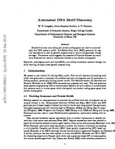
Fig. 1. The DNA motif for catalytic “seesaw” gates. (a) Abstract gate diagram. (b) The DNA gate motif and reaction mechanism. S1 , S2 , S3 , S4 are the recognition domains; T is the toehold domain; T ′ is the Watson-Crick complement of T , etc. Arrowheads mark the 3′ ends of strands. Black lines indicate elementary reactions via alternating strand displacement and toehold exchange. All reactions are reversible and unbiased; arrowheads indicate the dominant flows for the initial concentrations shown in (a). (c) The threshold motif and reaction mechanism. The toehold is extended by three bases (s′4 , the complement of the first three 5′ bases of S4 ), providing an increased rate constant relative to the gate itself. (d) Example sequences. Gate complexes and signal molecules are shown in their operational form (second column). To prepare gates from single strands of DNA, hairpin precursor molecules (third column) are cleaved by restriction enzymes to create functional gates. Recognition domain sequences are 15 nt and the toehold domain sequence is 5 nt.
A Simple DNA Gate Motif for Synthesizing Large-Scale Circuits
73
point, the gate base strand has its left toehold revealed, and its right toehold hidden: toehold exchange has been achieved, yielding the release of an output strand and the production of a gate:input complex. An analogous process allows the fuel strand to similarly displace the input strand from the new gate:input complex, completing a catalytic cycle that has the net effect of exchanging one left-side signal strand in solution (the fuel) for another left-side signal strand (the output). Note, however, that a free left-side signal strand (e.g. the fuel) cannot directly replace a bound left-side signal strand (e.g. the output bound to the gate). It can only do so in the presence of a right-side signal strand (e.g. the input) by an indirect sequence of events: the right-side signal strand displaces the bound left-side signal strand, and in turn the other left-side signal strand displaces the now-bound right-side strand. Thus, the right-side signal strand has catalyzed the exchange of the two left-side signal strands, which cannot exchange in its absence. This back-and-forth motion is the inspiration for our name for this motif: “seesaw gates”. In the above discussion, recognition domains S1 , S2 , and S4 played no active role in the mechanism. Rather, these domains allow the signal strands to interact with other gates and thus dictate connectivity within a circuit. For example, output strand S1 T S3 could also serve as a right-side signal strand for another gate with base strand T ′ S1′ T ′ , not shown here. However, while bound to base strand T ′ S3′ T ′ , signal strand S1 T S3 cannot act as a catalyst for the downstream gate because its toehold domain is sequestered. Of course, if it is released into solution by a strand displacement reaction, then it is free to act upon its target gate T ′ S1′ T ′ . In summary, each gate base strand consists of a single recognition domain identifying the gate, flanked by two toehold domains, only one of which is exposed at any given time; while each signal strand consists of two recognition domains identifying the two gates it connects, separated by a central toehold domain that is sequestered and thus inert when the signal strand is bound to a gate base strand. In addition to providing an ON/OFF switch for catalysis, threshold behavior can be helpful for reliable circuit function by cleaning up after leaky reactions. Fig. 1c shows a threshold gate that serves as a competitive inhibitor of the signal strand S3 T S4 . Because of the slightly longer toehold on the threshold gate, the signal strand will react faster with the threshold gate than with the original gate complex. (Toehold-mediated strand displacement reaction rates depend exponentially on toehold length, for short toeholds [21]. In this paper, we conservatively assume a 10-fold speed-up specific to the targeted signal strand, which is less than the ratio between the maximal rate constant for DNA hybridization and the measured rate constant for 5 nt toeholds [21]. In gates with more than one input, there will be some crosstalk if both inputs have a threshold, because the threshold for the first input can absorb the second input signal strand and visa versa, albeit at a 10fold slower speed. Thus, after one input exceeds its own threshold, it will continue to be absorbed by the other threshold – at the same rate with which it catalyzes the exchange of fuel and output signal. For the simulations presented in this paper we neglect this crosstalk, but simulations including the crosstalk reactions show
74
L. Qian and E. Winfree
qualitatively similar results, albeit less ideal. The problem also could be avoided by designing circuits in which only gates with a single input are allowed to have a threshold.) Once the signal strand has reacted with threshold gate, it will never be released because all relevant toeholds are sequestered – effectively, inert waste has been produced. Only after all the threshold gates have been used up, then the remaining signal strands can react (perhaps catalytically) with the original gate. This consistent and modular motif makes systematic construction of circuits logically straightforward, as discussed below, and further makes laboratory procedures for synthesizing gates and circuits plausible to carry out on a large scale. A substantial difficulty with our previous work [6,3] was that each gate substrate was a complex of multiple strands that had to be separately annealed together, and each complex had to be purified to remove excess single-stranded species and malformed gate substrates. Here, we aim to simultaneously prepare all gate complexes together in a single test tube; to do so, we must ensure that different gate species do not interact, and that the strands needed to form a given gate complex find each other efficiently. For our solution, we draw inspiration from the observation [22,23] that mixtures of hairpin molecules, when annealed, are likely to form non-interacting intramolecular hairpins even if at room temperature there exist lower free energy states involving intermolecular complexes. This occurs because the intramolecular hairpins are typically stable at some moderately high temperature, above the melting temperature of the intermolecular complexes – thus, during annealing, the hairpins form first and become kinetically trapped. The implication for gates is that if each gate species can be synthesized initially as a hairpin precursor, annealing all such gate precursors in a single reaction will result in a high yield of properly formed non-interacting molecules. Fig. 1d shows our realization of this scheme. After annealing, incubation with appropriate restriction enzymes removes the now-undesired linker subsequence, resulting in a well-formed complex of two strands. The entire solution could be purified by gel, since all gates are the same size; all threshold gates could be purified similarly. One way or another, making circuit function robust to sloppy parallel synthesis methods will be crucial to scaling up existing DNA circuits to hundreds or thousands of gates.
3
Abstract Circuit Formalism and Function
The abstract network representation introduced in Fig. 1a facilitates concise reasoning about circuits involving many interacting catalytic gates. In general, a circuit consists of a number of gate nodes and a number of wires between gate nodes. Each wire connects exactly two gates (Fig. 2b). Each gate consists of a left side and a right side, and it may connect to any number of wires on each side (Fig. 2a). Virtual gates (dotted lines) are gates whose total concentration is zero; they are used solely as syntactic sugar to provide a consistent naming scheme for wires that are connected on just one side, such as the input and output wires. When it is necessary to make the distinction, gates with non-zero concentration are referred to as real gates (solid lines). A seesaw gate circuit then consists of
A Simple DNA Gate Motif for Synthesizing Large-Scale Circuits (a)
75
i 1
w1i
2
w2i �
�
�
wNi
N
(b)
gi:i1 gi:i 2
g1i:i g 2i:i
1
wi 2
2
�
�
�
wiN
g Ni:i gi:iN
(c)
wi1
N
7 2 5
8
i
wij
1
3
9
10
j 6
4
Fig. 2. Abstract diagrams for seesaw gate circuits. (a) The general form of a gate node. Each gate may be connected to many wires on each side, potentially all N nodes in the network, including itself. (b) The general form of a wire. Each wire is specifically connected on its left end to the right side of a gate node, and connected on its right end to the left side of a gate node. (c) An example circuit with five real gates, five virtual gates, and eleven wires. Each wire is identified by the two gates it connects; thus the virtual gates serve to provide full names to their incident wires.
a number of gate nodes connected by wires between their left and right sides (Fig. 2c). The implementation of any such circuit diagram using DNA molecules is straightforward. (1) For a circuit with N gates, begin by chosing a set of N sufficiently distinct m-mer sequences S1 , S2 , . . . , SN . Sequence length m must increase (approximately logarithmically) with N ; the value m = 15 was used in Fig. 1. Use the same univeral toehold sequence T in all cases. (2) To each gate i, associate the gate base strand T ′ Si T ′ . To each wire ij, associate the wire signal strand Si T Sj . This determines the sequences for all molecules in the circuit. (3) Based on the desired initial concentrations of each signal strand, gate complex, and threshold, synthesize the appropriate hairpin molecules, cleave them with restriction enzymes, and purify the desired complexes. (4) To run the system, add the appropriate input signal strands and observe (e.g. by fluorescence) the target output signal strands. For standard nomenclature, a wire between gates i and j, with gate i on the left, is called wij , representing the free signal strand Si T Sj . Likewise, a gate i base strand T ′ Si′ T ′ bound to the left end of wire ij signal strand Si T Sj is referred to as gi:ij ; similarly gki:i is used when the right end of signal strand Sk T Si is bound to gate i. Note that gi:ii and gii:i refer to distinct complexes: in the former
76
L. Qian and E. Winfree
case, the signal strand is bound on its left end, leaving the gate’s left toehold accessible; while in the latter case the signal strand is bound on its right end, leaving the gate’s right toehold accessible. The threshold complex for wire ij into gate j is called thij:j , and similarly for thi:ij . In a slight abuse of notation, in the formulas below, wij refers both to the signal strand molecule itself and to the concentration of that species, and similarly for the gate and threshold complexes. Finally, note that although each gate has an identifying number corresponding to its base strand sequence, circuit diagrams may be drawn without any numerical annotation as the names are not relevant to circuit function. Because all components are in a standard form, the set of chemical reactions modelling the toehold exchange steps and threshold absorption steps can be written concisely. For all i, j, k ∈ {1, 2, . . . , N }, k
0 ⇀ ↽
wji + gi:ik
gji:i + wik
k0
(1)
k
k
wij + thij:j →1 waste ←1 thi:ij + wij
(2)
where the variables refer to the molecular species. Using standard mass action chemical kinetics, this gives rise to a system of ordinary differential equations (ODEs) for the dynamics. In the following, wij and similar terms refer to the concentrations of the respective species, rather than to the species themselves. � N � � d wij (3) = k0 wni · gi:ij + wjn · gij:j − wij · gni:i − wij · gj:jn dt n=1 −k1 (wij · thi:ij + wij · thij:j ) d gi:ij = k0 dt
�
d gij:j = k0 dt
�
N �
wij · gni:i − wni · gi:ij
n=1 N �
�
wij · gj:jn − wjn · gij:j
n=1
(4)
�
d thi:ij = −k1 · wij · thi:ij dt d thij:j = −k1 · wij · thij:j dt
(5)
These dynamics have conserved quantities for each gate node i and for each signal wire ij: def
gi:ij − thi:ij + wij + gij:j − thij:j = cij N �
def
gni:i + gi:in = ci
n=1
d cij d ci = = 0 dt dt
(6)
A Simple DNA Gate Motif for Synthesizing Large-Scale Circuits
77
Furthermore, the equilibrium (if it is obtained) enforces a simple relationship between the free and bound forms of the signal strands, namely that their ratio with respect to a particular gate must be identical for all wires connected to that gate. This follows immediately from Eq. 1 and the detailed balance equation k0 · wji · gi:ik = k0 · gji:i · wik . To wit, for each gate i, at equilibrium all wires achieve the ratio w1i w2i wN i wi1 wi2 wiN def = = ··· = = = = ··· = = ri g1i:i g2i:i gN i:i gi:i1 gi:i2 gi:iN
(7)
As an example, we can calculate the equilibrium concentrations for a single real gate, i, connected only to virtual gates, as in Fig. 1a. The equilibrium wire concentration wij (∞) depends upon the gate ratio and the initial concentrations on that wire: wij (∞) (gi:ij (∞) + wij (∞)) gi:ij (∞) + wij (∞) ri ri = (gi:ij (0) + wij (0) − thi:ij (0)) = cij 1 + ri 1 + ri
wij (∞) =
The equilibrium gate ratio ri can be calculated from the conserved quantities of Eqs. 6 and the equilibrium constraints of Eq. 7: � wji + wij ci = (1/ri ) cij = wij (1 + 1/ri ) j
from which it follows with a little algebra that ci ri . =1− � 1 + ri j cji + cij
ri 10 For the concentrations given in Fig. 1a, we can work out 1+r ≈ = 1− 10+10+1−0.5 i 0.51, so at equilibrium w13 = w23 ≈ 10x × 0.51 = 5.1x, as claimed earlier. The uniformity of components in seesaw gate circuits also facilitates their simulation. Using a general purpose mass action chemical kinetics simulator written by David Soloveichik in Mathematica, we have written routines for concisely representing, constructing, and simulating models of seesaw gate circuits.
4
Feedforward Digital Logic Circuits
Digital logic has two compelling features for circuit construction: first, it has proven to be very expressive for the synthesis of a wide range of desired behaviors; and second, it is intrinsically robust to a variety of manufacturing and operational defects. The basic principle underlying digital logic is that an intrinsically analog signal carrier may be considered simply to be either ON or OFF if at each stage of computation, signals are either pushed toward the ideal ON value or pushed toward the ideal OFF value. This is called signal restoration,
78
L. Qian and E. Winfree
(a) Input1: w13
Input2: w23
Output : w34
1
w13 or w23
4
w13
3
w34
-.5 1.5 -.5 2.5
2
5
w23
(b) Input1: w12
Input2: w34
Output : w56
w12 and w34
6 5
w56
1.5 -.75
1
2.5
2
w12 -.5
7
2 -.5
8
10
4 0.5 -.5
3
w34
4 -.5
8 8
9
Fig. 3. The circuit diagram and input/output behavior of boolean logic gates. (a) A two-input OR gate. (b) A two-input AND gate. Simulations are performed with the reference concentration 1x = 30 nM.
because if noise or device imperfections slightly corrupt a signal, that deviation from ideal behavior is cleaned up (perhaps not completely) by subsequent processing without altering the interpretation of the signal as ON or OFF. In this section we will consider a digital abstraction in which signal concentrations below 0.1x are considered OFF, while signal concentrations above 0.9x are considered ON. Intermediate signal levels – in the transition region – are considered a fault because proper behavior of logic gates is no longer guaranteed for input levels in the intermediate range. Feedforward digital circuits are an important class of combinational circuits, i.e. memoryless circuits in which the inputs uniquely determine the outputs without need to re-use any parts of the circuit. It is well known that any boolean function can be computed (usually quite efficiently) by a well-designed feedforward circuit built from AND, OR, and NOT gates. Interestingly, with a small cost in circuit size and a minor change in representation, called “dual-rail logic”, AND and OR by themselves suffice. We will therefore provide constructions for these basic operations, in addition to signal fan-in, fan-out, routing, and thresholding that may be required to paste the computing gates together into large circuits. The OR gate (Fig. 3a) is a simple extension of the basic catalyst (Fig. 1a) in which there are two input wires, 13 and 23, that serve as catalysts for the release onto output wire 34, driven by exchange with the “power supply” wire 35. Under the assumption that the threshold gate reaction rate constant, k1 , is
A Simple DNA Gate Motif for Synthesizing Large-Scale Circuits
79
10 times faster than the gate reaction rate constant k0 , clean digital behavior is seen in the model. For larger ratios k1 /k0 , the sharpness of the threshold increases correspondingly. The AND gate is a little trickier. Essentially, the idea here is similar to what is done with transistors: control flow from a power supply using two regulatory gates in series, and only if both gates are active will the output be affected. However, in our case there is no actual flow, just a sloshing back and forth of the signals on the seesaw gates. (Recall that there is a constant total concentration of a given signal strand either free in solution or bound to the gate at either end.) That said, consider the circuit shown in Fig. 3b. First, if input signals 12 and/or 34 are OFF (i.e. between 0x and 0.1x), then they will be absorbed by their respective thresholds. Now consider that if input 34 is ON (i.e. between 0.9x and 1x), then it can catalyze the power supply 49 to push strands onto the wire 48. Gate 8 serves as a signal reflector, effectively routing a signal emanating from the right side of a gate to arrive at the right side of another gate. (Recall that wires can only connect left sides to right sides, so this cannot be achieved directly.) Once the input to gate 8 exceeds its threshold, the right-side catalyst will be released, in turn catalytically releasing strand 28 to impinge on gate 2. But, if input 12 remains OFF, there will be no catalysis and therefore no signal will be pushed onto wire 25. On the other hand, if input 12 is also ON, the signal on 28 will provide power to push signal onto 25, which will in turn exceed the threshold for gate 5 and catalyze the production of output 56. The final case we must consider is if input 34 is OFF but input 12 is ON. In this case, there is at most 0.5x input 12 remaining after absorption by the threshold; some of it will end up bound to gate 2 after having pushed some 25 onto the output wire; however, at most a total of 0.5x can be pushed onto 25, and this will be absorbed by the gate 5 threshold. Because the total signal on gate 2 must remain at 2x, we see that all signal strands will remain bound to gate 2, the wires 12 and 25 will be empty, and no output 56 will be produced. This is of course considered OFF by the digital abstraction. Full simulations bearing out these intuitive considerations are shown. Fan-in and fan-out are handled easily using these constructions. More than two inputs (additional fan-in) to an OR gate simply requires additional wires connecting to the seesaw gate node, slight adjustments to the initial concentrations, and placing the threshold in a separate subsequent gate (to avoid the threshold crosstalk problem). More than one output (fan-out) from an OR gate is correspondingly simple: connect more output wires. Fan-out from an AND gate is analogous, but additional fan-in poses problems: a longer sequence of regulatory gates in series would require the initial power supply concentration to be considerably larger. Thus it is preferable to construct a multi-input AND gate as a binary tree of two-input AND gates. Because NOT gates appear to be difficult to implement directly (although we have not yet outlawed the possibility), the dual-rail convention is used. The following procedure may be used to convert a single-wire digital logic circuit (that may use AND, OR, NOT, NAND, and NOR) into an equivalent dual-rail
80
L. Qian and E. Winfree
(a)
(b)
10 11 20
1 2 6
21
3
30
4
31
60
0
61
7 5
4
41
70 71
50 51
(c)
10
11
20
21
30
60 61
31 40 70 1
4
71
50
51
Fig. 4. Compiling boolean logic circuits. (a) A sample circuit with 6 gates. (b) Translation into an equivalent dual-rail circuit with 12 gates. (c) Translation into an equivalent seesaw gate circuit with 36 gates.
circuit (which uses only AND and OR), as illustrated in Fig. 4ab. In the new circuit, which will contain at most twice as many gates, each wire z is replaced by two wires, z 0 and z 1 . If neither new wire is ON, this indicates that the logical value of z has not been computed yet; if z 0 is ON, this indicates that the logical value of z must be OFF; while if z 1 is ON, this indicates that the logical value of z must be ON. (If both z 0 and z 1 are ON, then the circuit is experiencing
A Simple DNA Gate Motif for Synthesizing Large-Scale Circuits
81
71=1 when input = [1,1,0,0,1]
ON state
70=1 when input = [0,1,1,1,1]
OFF state
Fig. 5. Simulation results for all 32 possible input vectors. The concentrations of all four dual-rail output species are shown as a function of time. Delays vary with the input, depending the shortest decision path through the network.
a fault.) With this representation, each original two-input boolean logic gate can be implemented using one AND gate and one OR gate. XOR can be easily implemented in dual-rail logic as well, although it requires 4 OR gates and 2 AND gates. In terms of DNA molecules, the difficulty implementing NOT gates derives from the need to detect and act on the absence of an input strand, but the action must not take place before the computation has reached this point in the circuit. One possible solution could be to use a clock signal to initiate the action, or lack of it, at the appropriate time. This is effectively what dual-rail logic does, except that explicit clocks are unnecessary because every signal value (once computed) is represented by the presence of an appropriate molecule that, in itself, can serve as a timing signal as well. To demonstrate these concepts, we compiled a small circuit (5 inputs, 6 NAND gates, 2 outputs) from its original netlist specification (Fig. 4a), to the equivalent dual-rail circuit consisting of only AND and OR gates (Fig. 4b), and then to its implementation as a network of seesaw gates (Fig. 4c). Because the thresholds on downstream gates drain the outputs of upstream gates and thus shift the equilibrium, for successful composition it was necessary to adjust the initial concentrations shown for isolated subcircuits in Fig. 3. It was also necessary to provide fan-out gates for inputs that were used more than once, and to add final read-out gates to properly drain the adjusted AND and OR subcircuits. The corresponding system of ODEs describing the network’s mass action kinetics were then simulated for all 32 possible input combinations. (The compiler and simulator was written in Perl and Mathematica.) As shown in Fig. 5, in every case both outputs reached either a clear “0” or “1” concentration level, which was verified to be correct. This provides concrete evidence that the digital logic subcircuits compose well.
82
L. Qian and E. Winfree
5
Relay Contact Circuits
In his seminal 1940 Master’s Thesis [24], Claude Shannon established a systematic symbolic approach to the analysis and design of digital circuits. A prevalent technology at the time was relay contact circuits, in which input switching signals (A, B, C, . . .) opened or closed electrical contacts in a network, either allowing current to flow through the network, or not. Like circuits made of AND, OR, and NOT gates, relay contact circuits can concisely implement arbitrary boolean functions. (Here we consider only circuits of primary relays – those directly controlled by external input signals.) To illustrate the flexibility of the seesaw gate motif, we provide a general method to compile relay contact circuits down to equivalent seesaw gate circuits. The basic primitives for constructing relay contact networks are simple. A circuit with one switch (Fig. 6a) corresponds to a single seesaw gate. The current signal is represented by the free signal strands of the seesaw gate, and the switching signal is represented by the input catalyst strands. Signal is produced on the output wire if and only if the switching signal A is ON. Two switches in series perform an AND operation (Fig. 6b). Since the connectivity of seesaw gates is oriented, we make each wire always connect two different sides of the gates in the design. The two seesaw gates corresponding to the circuit “A and
(a)
(b)
A
A and B A
A
B A
A 10
10
(c)
10
(d)
A or B
10
AB or AC or BC A
A
B 10
B A
A
B 10
10
B 10
C
10
10
B
C
10 10
10
B
10
A
10
10
C 10
B
(e)
A
(f) Restored current signal 100
Switching signal
Reversed fan-out signals
1 1 1 10
Fan-out signals
Current signal 10 -.5 100
1 1 1
1
Fig. 6. Implementation of relay circuits. (a) A simple circuit with current source (battery) and controlled device (denoted by a resistor), and the corresponding seesaw gate circuit. (b) AND logic. The “left” side of each seesaw gate is shaded. (c) OR logic. (c) A more complex circuit. (e) Input signal fan-out for both left-side and right-side wires. (f) Restoration for output and intermediate signals.
A Simple DNA Gate Motif for Synthesizing Large-Scale Circuits
83
B” therefore must have different sides connected. Two switches in parallel perform an OR operation (Fig. 6c). The only innovation here is that two distinct input and output wires are used. Fan-out at the current source can provide such a signal, and an OR gate at the current drain can consolidate the output into a single wire, if desired. For more complex circuits, such as the one in Fig. 6d, a number of additional issues arise. First, there may be two possibilities for the current direction through a given relay (such as C). We use a pair of seesaw gates in such cases. The current flow from A to C to A will go through the seesaw gate C on the left while the current flow from B to C to B will go through the other one on the right. This provides the basis for a general construction. Each original contact relay is replaced by a pair of seesaw gates, one prepared for each possible current flow direction. Output of each gate is routed to all other connected gates in the given flow direction. Thus, for each input setting, if there exists a connected path in the relay circuit, then there is a directed path of catalytically active gates in the seesaw gate circuit. Second, because we need different switching signal strands for different seesaw gates representing the same logical input (such as A, B, and C in Fig. 6d), and we also may need to connect them to either the “left” or the “right” side of the gate (as for C in Fig. 6d), we make use of a signal fan-out unit producing any number of signals in both the forward and reversed directions (Fig. 6e). Finally, if we use a uniform gate:output concentration (say 10x), the current signal will decrease as it passes through each seesaw gate. Thus, we need to restore the current at any place the signal becomes weak. This can be achieved by an amplifier with a threshold (Fig. 6f). Following this procedure, any relay contact circuit can be implemented with seesaw gates.
6
Analog Time-Domain Circuits and Feedback
The behavior of seesaw gate circuits is intrinsically analog. Following the approach of [3], we construct amplifier cascades with initial quadratic growth and with initial exponential growth. More complex temporal dynamics can also be synthesized, such as a pulse generator. The amplifier shown in Fig. 7a is a two-stage feedforward cascade. Input signal 12 catalytically pushes strands onto wire 24, which exhibits linear growth with time. Signal 24 also serves as catalysts for the release onto output wire 46, which in turn grows quadratically with time. The amplifier shown in Fig. 7b is a one-stage feedback cascade. Initially, input signal 12 catalytically releases strands onto output wire 22. However, signal strand 22 contains the recognition domain of gate 2 on both left side and right side, and therefore can play the role of the input signal once released, binding to the gate:output complex by its right side. Thus, strand 22 is also catalytically active in releasing additional copies of itself, resulting in exponential growth of the signal. The pulse generator shown in Fig. 7c illustrates a non-amplifying temporal dynamic. The basic idea is that the input strand 45 initially releases a large amount of output 24, but this is slowly absorbed by gate 2. The large gate 2
84
L. Qian and E. Winfree
1
4
2
w12
100
100
3
Output : w22
(b) Input : w12
w46
1
1
6
5
w12 et
w22 1
Input: 0.0001x ~ 0.1x
w12 t 2
Output : w46
(a) Input : w12
Input: 0.0001x ~ 0.1x
2 1 100
w12
(c) Input : w45
3
Output : w24 3
Input: 1x ~ 5x 2
1 1
4
100
w24
1
5
w45
Fig. 7. Analog time-domain circuits. (a) A catalytic cascade that exhibits initially quadratic growth. Temporal trajectories are shown for a serious of exponentially decreasing initial input concentations. (b) A positive feedback circuit that exhibits initially exponential growth. A series of exponentially decreasing input concentrations yields a series of trajectories with linearly increasing half-completiong times. (c) A pulse-generating circuit. Pulse amplitude depends on the input concentration. Simulations use 1x = 30 nM.
concentration ensures that signal on wire 24 returns to a small value at equilibrium, because the gate-to-wire ratio for wire 24 must be the same as that for 23, which cannot be higher than 0.01x.
7
Discussion
This project was inspired by the remarkable success of scaffolded DNA origami [15,25,26] for programming the self-assembly of hundreds of DNA strands into a single target structure. Self-assembly was extraordinarily reliable despite that DNA sequences could not be optimized to avoid undesired binding interactions and that unpurified DNA strands were used, for which the strand concentrations were not precisely known and many molecules were presumably incomplete or damaged. We were therefore looking for an analogous design for hybridizationbased DNA catalysts and circuits that would require minimal sequence design effort and work well even with unpurified strands and unreliable concentrations.
A Simple DNA Gate Motif for Synthesizing Large-Scale Circuits
85
Does our proposed seesaw gate motif live up to hopes and expectations as a DNA circuit component suitable for scaling up to large and complex circuits? We see some encouraging features, some concerns, and some clear challenges. First, design of large feedforward digital circuits looks promising. At the highest level, abstract specifications for circuit function can be expressed concisely using existing hardware description languages such as Verilog [27,28] and VHDL [29], then compiled down to a gate level netlist specifying elementary gates (AND, OR, NOT, NOR, NAND, XOR) and their connectivity. Thus, the sheer complexity of large-scale circuit design can be managed by off-the-shelf tools. The next step is compiling the digital logic netlist down to the seesaw gate circuit abstraction, using the constructions described above for dual-rail logic. This is straightfoward if no circuit size optimizations are attempted. To achieve the final step of designing molecules, we must assign sequences to each gate base strand. For this purpose, a single large set of sufficiently distinct domain sequences would enable construction of any circuit containing up to the given number of seesaw gates. Can we design sufficiently many domain sequences to scale up to circuits with many gates? We consider two design criteria: (1) signal strands should not have secondary structure and should not interact with each other, and (2) strand displacement should be unable to proceed if the invading sequence is not an exact match. The first criterion can be satisfied by standard DNA sequence design methods [30,31]; here we take the easy approach by using a three letter code (A, C, and T) for the signal strands, thus ensuring that problematic secondary structures and interactions are unlikely [32,33,34]. The gate base strand will therefore consist of (A, G, and T). A universal 5 nt toehold sequence may be used for all nodes, since specificity of interactions arises from uniqueness of the recognition domain sequences. Because of the complete independence of domains within the seesaw gate motif, no system-level conflicts are generated when strand sequences are generated by concatenation. The second criterion may be formalized as combinatorial sequence constraints. For example, we could require that at least 30% of bases are different for any two distinct recognition domains; as each mismatch impedes branch migration speed by a factor of roughly 10 [35,36], even 5 mismatches will dramatically reduce crosstalk. Additionally, we require that mismatches are spread out, so that when the wrong signal strand interacts with a gate, it will quickly encounter difficulties and dissociate; specifically, the longest run of matches must be less than 35% of the domain length. Finally, to prevent synthesis errors and ensure comparable melting temperatures, we require that there are no more than 4 A’s or T’s in a row, no more than 3 C’s or G’s in a row, and that sequences have between 30% and 70% GC-content. (Cf. constraints 1,7,8 of [37].) Using a “sphere-packing” technique [38], we have found sets of codes of sizes 76, 559, 5181, and ≫ 11, 000 for recognition domains of lengths 10, 15, 20, and 25, respectively, confirming the theoretically expected exponential growth in codebook size. This is enough to construct some interesting circuits. The caveat is that we are not certain that molecules designed using these criteria will work consistently in the laboratory.
86
L. Qian and E. Winfree
Can so many distinct sequences be synthesized and handled in the laboratory? Promising synthesis techniques include the Agilent SurePrint inkjet microarray spotter, which is advertized to be capable of synthesizing roughly 250, 000 distinct sequences per slide [39,40]; based on typical DNA array densities and slide dimensions, this corresponds to ≈ 0.040 fmol per spot. If each spot provides a 0.25x concentration (the minimal increment we use) in our chosen reaction volume, then a gate complex using 6x would require the use of 24 spots. If we define the complexity of a seesaw gate circuit to be the total initial concentration of strands, in 1x units, then the Agilent technology would allow us to create circuits of complexity up to 62, 500x. (This corresponds to either ≈ 15, 000 OR gates or ≈ 4500 AND gates for the concentrations used in Fig. 5.) NimbleGen has a similar technology, capable of producing 350, 000 distinct 85-mers [41], and we can expect technologies capable of synthesizing longer strands in the near future. The hairpins in Fig. 1d are up to 91 nucleotides long, which we consider to be synthesizable. After synthesis, linkers attaching strands to the slide can be cleaved, and a mixture of all strands can be collected in a single tube, annealed to form hairpins, digested with restriction enzymes to produce gates, and then gel-purified to eliminate non-functional molecules. Thus, all molecules for the entire circuit are synthesized and processed in parallel in a single tube. Once designed and synthesized, will they work? The first question is speed. If the maximum total concentration for reliable DNA gate operation is 100 µM (perhaps optimistic), then 1x would be 1.6 nM for a 62, 500x circuit, and the slowest reaction half-times (the effective gate delay) would be 3 days if k0 = 104 /M/s and k1 = 106 /M/s. This is too slow. Either one must resign oneself to smaller circuits, for which the concentrations can be higher, or one must find a way to speed up hybridization reactions in dilute complex mixtures. PERT [42,43] claims to be such a method; in which case, k0 = 108 and k1 = 1010 may be possible. This would reduce the 3 days to 30 seconds. The second question is whether the computation will be correct. For feedforward digital circuits, thresholding and signal restoration – the digital abstraction – is expected to provide some robustness to variations in concentrations, to leak, and to minor crosstalk. However, experimental exploration of seesaw gate circuits will be needed to evaluate the potential for producing reliable function in practice. We anticipate that there will be many unforeseen difficulties. In summary, we have proposed a new catalytic DNA gate that appears to be suitable for scaling up to analog and digital circuits incorporating thousands of gates with a reasonable expectation that adequate speed and reliability could be achieved. However, a limitation of this work is that the circuit constructions we described all function by completely depleting key fuel species, hence each circuit preparation can be used only once. An important goal is to implement sequential circuits containing buffers, flip-flops, resets, and clocks that orchestrate the re-use of circuit elements and can process time-varying input signals. We do not know at this point whether this limitation is essential to the seesaw gate motif, or whether we have just not yet been clever enough to see how to do it. Similarly, we do not yet
A Simple DNA Gate Motif for Synthesizing Large-Scale Circuits
87
have a characterization of the class of analog dynamics that can be achieved, although it appears to be a rich space of behaviors. On the practical side, interfaces between DNA circuits and other chemical reactions will be necessary if DNA circuits are to serve as embedded controlers for molecular events.
Acknowledgements The authors thank Dave Zhang for discussion of the catalytic mechanism, Marc Riedel for providing example netlists from logic synthesis benchmarks, Virgil Griffith for suggesting useful techniques for DNA sequence design, Ho-Lin Chen and Shuki Bruck for suggesting the connection to relay circuits, David Soloveichik for Mathematica code for simulating chemical reaction networks, and Georg Seelig, Bernard Yurke, and everyone else for discussions and support. This work has been supported by NSF grant no. 0728703 and HFSP award no. RGY0074/2006-C.
References 1. Tang, J., Breaker, R.R.: Rational design of allosteric ribozymes. Chem. Biol. 4, 453–459 (1997) 2. Turberfield, A.J., Mitchell, J.C., Yurke, B., Mills Jr., A.P., Blakey, M.I., Simmel, F.C.: DNA fuel for free-running nanomachines. Physical Review Letters 90(11), 118102–118104 (2003) 3. Zhang, D.Y., Turberfield, A.J., Yurke, B., Winfree, E.: Engineering entropy-driven reactions and networks catalyzed by DNA. Science 318, 1121–1125 (2007) 4. Stojanovic, M.N., Mitchell, T.E., Stefanovic, D.: Deoxyribozyme-based logic gates. Journal of the American Chemical Society 124, 3555–3561 (2002) 5. Hagiya, M., Yaegashi, S., Takahashi, K.: Computing with hairpins and secondary structures of DNA. In: Chen, J., Jonoska, N., Rozenberg, G. (eds.) Nanotechnology: Science and Computation, pp. 293–308. Springer, Heidelberg (2006) 6. Seelig, G., Soloveichik, D., Zhang, D.Y., Winfree, E.: Enzyme-free nucleic acid logic circuits. Science 314, 1585–1588 (2006) 7. Penchovsky, R., Breaker, R.R.: Computational design and experimental validation of oligonucleotide-sensing allosteric ribozymes. Nat. Biotechnol. 23(11), 1424–1433 (2005) 8. Macdonald, J., Li, Y., Sutovic, M., Lederman, H., Pendri, K., Lu, W., Andrews, B.L., Stefanovic, D., Stojanovic, M.N.: Medium scale integration of molecular logic gates in an automaton. Nano Letters 6, 2598–2603 (2006) 9. Yashin, R., Rudchenko, S., Stojanovic, M.N.: Networking particles over distance using oligonucleotide-based devices. Journal of the American Chemical Society 129, 15581–15583 (2007) 10. Seeman, N.C.: An overview of structural DNA nanotechnology. Mol. Biotechnol. 37, 246–257 (2007) 11. Bath, J., Turberfield, A.J.: DNA nanomachines. Nature Nanotechnology 2, 275–284 (2007) 12. Gartner, Z.J., Liu, D.R.: The generality of DNA-templated synthesis as a basis for evolving non-natural small molecules. Journal of the American Chemical Society 123, 6961–6963 (2001)
88
L. Qian and E. Winfree
13. Gothelf, K.V., LaBean, T.H.: DNA-programmed assembly of nanostructures. Organic & Biomolecular Chemistry 3, 4023–4037 (2005) 14. Winfree, E., Liu, F., Wenzler, L.A., Seeman, N.C.: Design and self-assembly of two-dimensional DNA crystals. Nature 394, 539–544 (1998) 15. Rothemund, P.W.K.: Folding DNA to create nanoscale shapes and patterns. Nature 440, 297–302 (2006) 16. Yin, P., Choi, H.M.T., Calvert, C.R., Pierce, N.A.: Programming biomolecular self-assembly pathways. Nature 451, 318–322 (2008) 17. Turing, A.M.: The chemical basis of morphogenesis. Philosophical Transactions of the Royal Society (part B) 237, 37–72 (1953) 18. Zhabotinsky, A.M.: A history of chemical oscillations and waves. Chaos 4, 379–386 (1991) 19. Abelson, H., Allen, D., Coore, D., Hanson, C., Homsy, G., Knight Jr., T.F., Nagpal, R., Rauch, E., Sussman, G.J., Weiss, R.: Amorphous computing. Communications of the ACM 43, 74–82 (2000) 20. Zhang, D.Y., Winfree, E.: Control of DNA strand displacement kinetics using toehold exchange (in preparation) 21. Yurke, B., Mills Jr., A.P.: Using DNA to power nanostructures. Genetic Programming and Evolvable Machines 4, 111–122 (2003) 22. Dirks, R.M.: Analysis, design, and construction of nucleic acid devices. PhD thesis, California Institute of Technology (2005) 23. Bois, J.S.: Analysis of interacting nucleic acids in dilute solutions. PhD thesis, California Institute of Technology (2007) 24. Shannon, C.E.: A symbolic analysis of relay and switching circuits. Technical Report Master’s Thesis, Massachussetts Institute of Technology (1940) 25. Qian, L., Wang, Y., Zhang, Z., Zhao, J., Pan, D., Zhang, Y., Liu, Q., Fan, C., Hu, J., He, L.: Analogic china map constructed by DNA. Chinese Science Bulletin 51, 2973–2976 (2006) 26. Douglas, S.M., Chou, J.J., Shih, W.M.: DNA-nanotube-induced alignment of membrane proteins for NMR structure determination. Proc. Nat. Acad. Sci. USA 104, 6644–6648 (2007) 27. Thomas, D.E., Moorby, P.R.: The Verilog Hardware Description Language. Kluwer, Dordrecht (1991) 28. Golze, U.: VLSI Chip Design with the Hardware Description Language VERILOG. Springer, Heidelberg (1996) 29. Shahdad, M., Lipsett, R., Marschner, E., Sheehan, K., Cohen, H., Waxman, R., Ackley, D.: VHSIC hardware description language. IEEE Computer 18, 94–103 (1985) 30. Brenneman, A., Condon, A.: Strand design for biomolecular computation. Theor. Comput. Sci. 287, 39–58 (2002) 31. Bishop, M.A., D’Yachkov, A.G., Macula, A.J., Renz, T.E., Rykov, V.V.: Free energy gap and statistical thermodynamic fidelity of DNA codes. Journal of Computational Biology 14, 1088–1104 (2007) 32. Mir, K.U.: A restricted genetic alphabet for DNA computing. In: Landweber, L.F., Baum, E.B. (eds.) DNA Based Computers II. DIMACS, vol. 44, pp. 243–246. American Mathematical Society, Providence (1998) 33. Braich, R.S., Chelyapov, N., Johnson, C., Rothemund, P.W.K., Adleman, L.M.: Solution of a 20-variable 3-SAT problem on a DNA computer. Science 296, 499–502 (2002)
A Simple DNA Gate Motif for Synthesizing Large-Scale Circuits
89
34. Faulhammer, D., Cukras, A.R., Lipton, R.J., Landweber, L.F.: Molecular computation: RNA solutions to chess problems. Proc. Nat. Acad. Sci. USA 97(3), 1385–1389 (2000) 35. Panyutin, I.G., Hsieh, P.: Formation of a single base mismatch impedes spontaneous DNA branch migration. Journal of Molecular Biology 230, 413–424 (1993) 36. Panyutin, I.G., Hsieh, P.: Kinetics of spontaneous DNA branch migration. Proc. Nat. Acad. Sci. USA 91, 2021–2025 (1994) 37. Kao, M.-Y., Sanghi, M., Schweller, R.T.: Randomized fast design of short DNA words. In: Caires, L., Italiano, G.F., Monteiro, L., Palamidessi, C., Yung, M. (eds.) ICALP 2005. LNCS, vol. 3580, pp. 1275–1286. Springer, Heidelberg (2005) 38. King, O.D.: Bounds for DNA codes with constant GC-content. Electronic Journal of Combinatorics 10, R33 (2003) 39. Agilent Technologies. SurePrint technology (web page), http://www.chem.agilent.com/scripts/generic.asp?lpage=557 40. Agilent Technologies. Multi-pack gene expression microarrays (web page), http://www.chem.agilent.com/scripts/generic.asp?lpage=51683 41. NimbleGen Systems, Inc. Array synthesis (web page), http://www.nimblegen.com/technology/manufacture.html 42. Kohne, D.E., Levison, S.A., Byers, M.J.: Room temperature method for increasing the rate of DNA reassociation by many thousandfold: The phenol emulsion reassociation technique. Biochemistry 16, 5329–5341 (1977) 43. Goldar, A., Sikorav, J.-L.: DNA renaturation at the water-phenol interface. Eur. Phys. J. E. 14, 211–239 (2004)