Fizika Nizkikh Temperatur, 2011, v. 37, No. 5, p. 535–538
A simple low-temperature adiabatic calorimeter for small samples M.I. Bagatskii, V.V. Sumarokov, and A.V. Dolbin B. Verkin Institute for Low Temperature Physics and Engineering of the National Academy of Sciences of Ukraine 47 Lenin Ave., Kharkov 61103, Ukraine E-mail:
[email protected] Received January 27, 2011 3
A simple adiabatic calorimeter has been made to investigate the heat capacity of small samples (≤ 1 cm ) of carbon nanomaterials in the temperature range from 1 to 300 K. It makes possible: i) short-time mounting of a sample; ii) doping of samples with gases directly in the calorimeter; iii) short-time cooling of a sample down to helium temperatures. The adiabatic calorimeter is suitable to place into a helium vessel of a portable Dewar or a helium cryostat. The heat capacity of the fullerit sample has been measured in the temperature range from 1 to 30 K. PACS: 81.05.U– Carbon/carbon-based materials; 65.40.Ba Heat capacity. Keywords: low-temperature adiabatic calorimeter, heat capacity of fullerite C60.
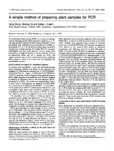
We describe a rather simple adiabatic calorimeter to study the influence of gas admixture on the heat capacity of small samples of carbon nanomaterials. The size of the samples is small: ≤10 mm in diameter with the volume of 3 ≤1 cm . The calorimeter was operated in temperature range 1–300 K. The schematic view of the low-temperature part of the adiabatic calorimeter is shown in Fig. 1. Test sample 5 is mounted in calorimeter 6. The calorimeter is a thin-walled copper cup (≈ 4 mm high, inner diameter ≈ 12 mm) soldered to a copper-foil shell (0.03 mm thick). Thermometer 4 is fixed at the outer surface of the copper cup bottom inside the shell. Heater 7 (130 Ohms) of the calorimeter is made of manganin wire wound bifilarly onto the outer surface of the shell and cemented with butvar-phenolic adhesive (BP-2) for a better thermal contact between the calorimeter and the heater. Copper wires (0.18 mm in diameter) are fixed with BP-2 onto the inner surface of the shell. The wire ends are electric terminals soldered to the wires of thermometer 4, heater 7 of the calorimeter and the wires running from of adiabatic shield 8. The mass of the calorimeter was about 0.8 g. A thin layer of the vacuum Apiezon grease was applied to the bottom of calorimeter to improve the thermal contact between sample 5 and calorimeter 6. The calorimeter is suspended inside thermal shield 8 on manganin wires running from the thermal shield to the thermometer and the heater of the calorimeter. It is centered with Kevlar threads. The calorimeter is cooled through the manganin wires. © M.I. Bagatskii, V.V. Sumarokov, and A.V. Dolbin, 2011
Thermal shield 8 was mounted below helium bath 9 using special thermoinsulating suspensions 21. The components of the calorimeter are shown in Fig. 2. 3 Bath 9 (about 7 cm ) is connected via thin-walled stainless steel pipe 10 (6 mm in diameter, 100 mm long) with adsorption pump 26 filled by absorbent carbon “SKN-1K” 3 (~24 cm ). The adsorption pump removes helium vapor from the bath. Pipe 10 is soldered to cold plate 11 with a 60% Sn–40% Pb solder that allows condensing helium to 4 3 bath 9. The bath can be filled with either He or He. This ensures the lowest temperature of the calorimeter down to ~ 4 1 or 0.3 K, respectively. He was used in this investigation. On measuring in the region below 2 K, the temperature of the bath 9 was held constantly at ~ 1 K for about six hours. 4 Above 2 K the calorimeter can be cooled by pumping He vapor from bath 9 or the helium bath of the cryostat. The temperature of adsorption pump 26 was controlled with carbon thermometer 15 and a differential copper– constantan thermocouple placed between the cold plate and the adsorption pump. The operation conditions of the adsorption pump are controlled with heater 14 wound onto the outer surface of heat exchanger 24. The calorimetric cell is placed into a vacuum chamber of an inset consisting of upper 25 and lower 3 parts. The upper part of the inset is made of a thin-walled stainless steel pipe. Its lower part is made of copper. There is a cold copper plate between the upper and lower parts of the calorimeter. The adiabatic calorimeter is suitable to place into a
M.I. Bagatskii, V.V. Sumarokov, and A.V. Dolbin
30
31 4
He
17
29 28
16
27 26 25 24
15 aaaaaaaaa aaaaaaaaa aaaaaaaaa aaaaaaaaa aaaaaaaaa aaaaaaaaa aaaaaaaaa aaaaaaaaa aaaaaaaaa aaaaaaaaa
23
14 13 12 11
22
10 9 21
20 19 18
8
aaaaaaaaaaaaaaaaaaaaa aaaaaaaaaaaaaaaaaa aaa aa 4
He
7 6 5 4 3 2 1
Fig. 1. The principal diagram of the low-temperature part of the calorimeter: 1 — a helium cryostat (or a portable Dewar); 2 — the helium container of cryostat; 3 — a body of the insert (lower part); 4 — the thermometer “CERNOX”; 5 — a sample; 6 — the calorimeter; 7 — the calorimeter heater; 8 — the adiabatic shield; 9 — the low-temperature chamber; 10 — a tube; 11 — a cold plate; 12, 15 — a carbon thermometer; 13 — a sorbent; 14 — the adsorber 4 3 heater; 16, 28, 29 — a valve; 17 — a pipe to He ( He) gas system; 18 — a vacuum part of the insert; 19 — a differential thermocouple Au + 0.03% Fe–Cu; 20 — the adiabatic shield heater; 21 — the suspension of the calorimetric cell; 22 — the low4 temperature joint; 23 — a channel for supplying by liquid He of the heat exchanger of the adsorber; 24 — the heat exchanger of the adsorber; 25 — the insert body (upper part); 26 — the adsorption pump; 27 — the helium pumping line via the adsorber heat exchanger; 30 — the helium pumping line; 31 — the lead-in.
helium vessel of a portable Dewar or a helium cryostat. The part of the inset that is immersed into the helium cryostat is 1 m long and 22 mm in outer diameter. Lowtemperature vacuum joint 22 was mounted on cold plate 11 to provide an access to the elements of the calorimetric cell. Cold plate 11 had holes for electric leads running from thermometer 4, thermocouple 19 and heaters 7 and 20 4 and channel 23 for supplying by liquid He of heat ex536
Fig. 2. The details of the calorimeter (with a technological gadget), the adiabatic shield with the system of suspension.
changer 24 of adsorption pump 26 from helium container 2 of the outside cryostat. Carbon thermometer 12 was mounted on the upper side of the plate. The temperature of the calorimeter is measured with a calibrated CERNOX CX-1010-SD-0.3D resistance thermometer (Lake Shore Cryotronics) connected to the measuring circuit in a four-wire configuration. The thermometer was fed with a precision dc voltage source with a periodically varying polarity, which minimized the effect of parasitic emf in the measuring circuit of the resistance thermometer. The adiabatic conditions of the experiment (dT/dt ≤ –3 –4 ≤ 10 –10 K/min) are maintained with a special electronic system controlling the temperature of the adiabatic shield. The system includes differential thermocouple [Au + 0.03 at.%Fe–Cu] 19 between calorimeter 6 and thermal shield 8, as well as thermal shield heater 20, photoelectric and power amplifiers. The calorimetric experiment was controlled with a personal computer (PC) using the data management and acquisition system based on a Keithley 2700/7700 multimeter. The PC and the measuring system were connected through an Advantech PC1-1671 interface board affording the IEEE-488 (GPIB) — standard data exchange. On reach–3 –4 ing the temperature run (≤10 –10 K/min) of the calorimeter, the Keithley 2700/7700 multimeter switches on a heater by the operator's command and thus ensures the preassigned heat input to the calorimeter. The characteristic variation of the calorimeter temperature during the time of heating is ΔТ ≈ 0.05 Т, where T is the temperature of the calorimeter. The time of heating varied within 1–5 min. The running time of the experiment is specified by the computer. The specific heat of the test sample of fullerite CF is described as follows: CF (T ) = [iU τ / (T2 − T1 ) − Cc ] / m f ,
where i is the current through the calorimeter heater during the time τ; U is voltage drop at the heater; T1 and T2 are the starting and final equilibrium temperatures of calorimeter, respectively; Cc is the heat capacity of the empty calorimeter; mf is the mass of the test sample; Т = T1 + (T2 – T1)/2. Fizika Nizkikh Temperatur, 2011, v. 37, No. 5
A simple low-temperature adiabatic calorimeter for small samples The relative error in the measurement of the heat introduced to the calorimeter (iUτ) is less than 0.2% in the whole temperature range. The main contribution to the error of the heat capacity measurement is made by the random and systematic errors occurring in estimation of the difference between the calorimeter temperatures T2 – T1. The equilibrium temperatures T1 and T2 were found by extrapolating the time dependences of the calorimeter temperature (dT/dt) measured in the equilibrium periods before and after heating to the mid-time of heating. The above errors in the temperature difference appear because of the inaccuracies in considering the residual heat exchange between the calorimeter and the thermal shield. The heat capacity of the empty calorimeter Cc was measured in a separate experiment. The experimental data of the heat capacity of the empty calorimeter and the smoothed curve are shown in Fig. 3. The smoothed curve was obtained through approximation of the experimental results by the i equation C = Σ aiT (i = 1, ..., 9) in a nonphysical form. The c.m.s. error is 1.3%. The deviation of the experimental data from the smoothed curve was up to about 1% at high temperatures and about 18% at the lowest temperature. To check the operation of the calorimeter, the heat capacity of the C60 sample was measured in the temperature interval 1–30 K. The test sample was a cylinder (≈ 6 mm high and 10 mm in diameter). The sample was prepared in Sweden (Umea University) by compacting a C60 powder under the pressure 1 kbar. The characteristic sizes of the C60 crystals were 0.1–0.3 mm. The purity of fullerite C60 was 99.99%. The masses of the C60 sample and the Apiezon grease were mf = (586.48 ± 0.05) mg and ma = (0.45 ± ± 0.05) mg, respectively. Before the experiment, the fullerite sample was held at T = 350 °C in a special device for 48 h under the condition of dynamic evacuation. This was done to remove the gas
impurities and moisture from the sample. Weighing and mounting the sample into the calorimeter and hermetic sealing of the vacuum chamber took several hours. Then the vacuum chamber of the calorimeter was “washed” several times with pure nitrogen gas and backing pumped for about eight hours. The residual N2 pressure in the chamber was up to several millitorrs. The experimental data on the total heat capacity of the calorimeter with the sample of fullerit C60, the empty calorimeter and the sample are illustrated in Fig. 4. The contribution of the Apiezon grease to the total heat capacity was accounted with using the literature data on the heat capacity of Apiezon from Ref. 1. The contribution of the sample to the total heat capacity of the calorimeter with the sample was 45% below 2 K, 75% at 4 K, 80% at 10 K, 70% at 20 K and 45% at 30 K. The temperature dependence of C60 specific heat obtained in this experiment is shown in Fig. 5 along with literature data [2–4]. The error in the determination of the specific heat of C60 is up to 20% at 2 K, 10% at 4 K and decreases to 3% as the temperature rises to 30 K. Note that the errors in the specific heat of C60 are not specified in Refs. 2–4. Atake et al. [2] used an adiabatic calorimeter to investigate the heat capacity of fullerite C60 in the temperature region 11–300 K. The C60 sample contained about 8% of graphite and its weight (≈ 0.88 g) was much lower than that of the calorimetric vessel (35 g). As a result, the contribution of the sample to the total heat capacity was only 8% at T = 20 K. The highest discrepancy between our results and the data of Ref. 1 is 12%. Beyermann et al. [3,4] measured the heat capacity of C60 at T = 1.4–20 K by the thermal relaxation method. The mass of the sample and the C60 purity are not specified in Refs. 3, 4. Two series of measurements were made. The
0.04 0.07 0.06
0.03
Ct
0.02
C, J/K
C, J/K
0.05 0.04 0.03
CF
0.02
0.01
Cc
0.01
0 0
5
10
15 T, K
20
25
30
Fig. 3. The temperature dependence of the heat capacity of the empty calorimeter. Experiment: open circle; solid line — a fitting curve. Fizika Nizkikh Temperatur, 2011, v. 37, No. 5
0 0
CA 5
10
15 T, K
20
25
30
Fig. 4. The total heat capacity Ct of the calorimeter with the sample, the heat capacities of the empty calorimeter Cc, the sample CF and grease Apiezon CA. 537
M.I. Bagatskii, V.V. Sumarokov, and A.V. Dolbin 0,06 C60
C, J/(g×K)
Conclusions
2 1
0,04 3 0,02
0,00 0
5
10
15 T, K
20
25
30
Fig. 5. The temperature dependence of the heat capacity of fullerit C60: from Refs. 3, 4 (1), this work (2), from Ref. 2 (3).
measurements in series II [4] were made after heating of the sample in vacuum at 430 K. Above 3 K the discrepancy between series I and II was no more than 16%. At T < 2 K the results of series I were an order of magnitude higher than those of series II. The data of Refs. 3, 4 exceeded our results systematically by 5–12% at T = 4–20 K. As the temperature lowers, the discrepancy between our results and those of Refs. 3, 4 increases. Thus, the results of this study agree quite well with literature data [2–4] in the region 4–30 K.
538
A simple adiabatic calorimeter has been made to investigate the effects of gas admixtures on the heat capacity of 3 small samples (with diameter ≤ 10 mm, 1 1 cm by volume) of carbon nanomaterials in the temperature range from 1 to 300 K. The design of the calorimeter makes possible: i) short-time mounting of a test sample, which is particularly important for investigations of both the heat capacity of pure nanomaterials and the effects caused by gas admixtures; ii) doping of a sample by gases directly in the calorimeter; iii) short-time cooling of a sample down to helium temperatures. The adiabatic calorimeter is suitable to place into a helium vessel of a portable Dewar or a helium cryostat. The heat capacity of the C60 sample has been measured in the temperature range 1–30 K. The results of this study agree quite well with literature data [2–4] in the region 4–30 K. 1. C.A. Swenson, Rev. Sci. Instr. 70, 2728 (1999). 2. T. Atake, T. Tanaka, H. Kawaji, K. Kikuchi, S. Saito, S. Suzuki, I. Ikemoto, and Y. Achiba, Physica C185–189, 427 (1991). 3. W.P. Beyermann, M.F. Hundley, J.D. Thompson, F.N. Diederich, and G. Grüner, Phys. Rev. Lett. 68, 2046 (1992). 4. W.P. Beyermann, M.F. Hundley, J.D. Thompson, F.N. Diederich, and G. Grüner, Phys. Rev. Lett. 68, 2737 (1992).
Fizika Nizkikh Temperatur, 2011, v. 37, No. 5