Progress In Electromagnetics Research B, Vol. 39, 163–178, 2012
A SIMPLE PATTERN RECOGNITION APPROACH FOR MONITORING INCIPIENT STATOR FAULTS IN SALIENT-POLE SYNCHRONOUS GENERATORS J. A. Dente and P. J. C. Branco* Instituto Superior T´ecnico (IST) — DEEC Energia, Technical University of Lisbon (UTL), Lisboa, Portugal Abstract—This paper studies the effect of incipient stator faults in salient-pole synchronous generators and its detection using a simple pattern recognition methodology. A theoretical linear model for the synchronous generator is first developed to provide the relationships between stator and rotor harmonic currents and possible incipient faults on stator electric circuits. All theoretical findings were verified by experimental results. The stator currents and its αβ and dq representations have been used to detect incipient faults on salient-pole synchronous generators using a similar pattern recognition technique which have been proposed for induction machines. From our test results, it became clear that the proposed methodology is capable of correctly monitoring incipient stator faults in salient-pole synchronous generators. 1. INTRODUCTION Synchronous generators play today a vital position in the renewable world due to their extensively use in wind power. It is very important to detect incipient faults in these generators to help their preventive maintenance, mainly without stopping the generator. Hence, monitoring and detection of faults in synchronous generators are crucial to the reliability of wind turbines as pointed out by Yang in [1]. Several techniques have been proposed to model and detect stator faults in synchronous generators. Some fault detection techniques are based on an analytic and physical model of the fault as, for example, Faiz et al. in [2], which developed a modified winding function method carrying out internal faults in synchronous generators, Received 21 January 2012, Accepted 28 February 2012, Scheduled 7 March 2012 * Corresponding author: Paulo Jos´ e da Costa Branco (
[email protected]).
164
Dente and Branco
and Hade et al. in [3], which have modeled a stator fault in interior permanent magnet synchronous motors but based on a parameter estimation methodology. Other techniques have used a black-box approach for modeling and fault detection in synchronous generators, which are based on some signal processing technique. Recently, wavelets have been applied for conditioning monitoring of salient-pole synchronous generator in transient conditions as shown by Yaghobi et al. in [4] and Karrari and Malik in [5]. One characteristic of all those techniques is their complexity and time consuming. Hence, it is in this context that some detection and diagnosis methodologies as those shown in [6] and [7], generally used in the induction machines for stator faults, can be adapted to salient-pole synchronous generators. These methodologies use the inverse phase voltage component that is induced in the stator coils due to an incipient stator fault on salient-pole synchronous machines. In this paper, the authors propose some electrical features that can be used as indicators of stator faults well before their defects have a significant advance. The negative sequence component of stator voltages and currents are then used as inputs to the pattern recognition algorithm. Experimental results are presented and allow verifying the good performance applicability of the adapted methodology to detect incipient stator faults in synchronous generators. 2. THEORETICAL ANALYSIS The majority of electrical machines can be seen as RL circuits described using Eq. (1). The methodology used in this paper considers a linear model for the synchronous machine, whereas speed remains constant and structural changes are small enough to not altering the sinusoidal topology of the machine (for example, saturation effects can be neglected since for incipient faults the stator currents will not reach a magnitude sufficient to saturate the electric machine). Therefore, our model characterizes the fault in its initial stage, avoiding the analysis of nonlinear systems. A fault in the electric circuits of the machine results in a parametric modification, i.e., change of induction coefficients and electrical resistances. ∂(LI) U = RI + (1) ∂t Generally speaking, conventional three-phase machines impose a condition of cyclic symmetry which characterizes the matrix of induction coefficients and electrical resistances. In case of fault, this cyclic symmetry is lost, resulting in a new matrix L0 (2) composed by the matrix L with cyclic symmetry plus other matrix ∆L, which is non-
Progress In Electromagnetics Research B, Vol. 39, 2012
165
cyclic due to parametric changes. Similarly, the electrical resistances matrix R is changed as in (3). L0 = L + ∆L R0 = R + ∆R
(2) (3)
Using (2) in (1), and considering that a parametric change causes a modification ∆I in the electric current, Eq. (1) can be written as (4). ∂ ((L + ∆L) (I + ∆I)) (4) ∂t Expanding (4) results in Eq. (5) where terms ∆R∆I and ∆L∆I can be neglected since they will present very low values given that the analysis is performed to an incipient fault state. U + ∆U = (R + ∆R) (I + ∆I) +
∂ (LI) ∂ (∆LI) + ∆RI + + R∆I ∂t ∂t ∂ (∆L∆I) ∂ (L∆I) + ∆R∆I + (5) + ∂t ∂t Equation (5) results in a linear combination of two cases: the first one referring to the no-fault condition (1), while the second case is the response of the machine to a given disturbance quantified by (6). In this equation, an ideal power supply with null impedance was considered (∆U = 0). U + ∆U = RI +
∂ (L∆I) ∂ (∆LI) = −∆RI − (6) ∂t ∂t It is verified that the machine responds to those incipient faults maintaining its conditions of symmetry, thus accounting for the appearance of electromotive forces (right term in (6)) that alter the electric currents. The appearance of those electromotive forces has consequences in terms of symmetrical components, since they can form a three-phase unbalanced system. Therefore, the presence of a negative component can be a good indicator of a possible abnormal condition, being thus interesting to verify the response of the synchronous generator to this component through its stator currents. R∆I +
3. FAULT IN THE ELECTRIC CIRCUITS OF A SYNCHRONOUS MACHINE The synchronous machine consists of two parts: ◦the stator, usually consisting of three RL circuits separated by 120 , as in Fig. 1(a), while in the rotor is mounted the excitation circuit consisting of RL windings or permanent magnets. The synchronous machine can be a
166
Dente and Branco
"
-T
+S
120º
+R
s0 240º
-S
-R
N
S
+T
(a)
(b)
Figure 1. (a) Synchronous machine stator. (b) Salient-pole rotor. salient-pole rotor (Fig. 1(b)) or a cylindrical rotor. In our analysis, saturation effects were neglected, so that induction coefficients will only depend on rotor position θ. To study the electrical faults in the synchronous machine, we assumed that those were generated in the stator circuits. Besides, as it is also unlikely that both stator faults occur simultaneously, they were considered separately in each phase. Applying the methodology developed in Section 2, which resulted in Eq. (6), this equation can be rewritten as (7). From now on the electrical resistances are ignored because they generally show a low value compared to inductive reactances. ∂ (∆L) ˙ ∂I ∂(L∆I) θI − ∆L = (7) ∂θ ∂t ∂t The induction coefficients are represented by matrix L in (8) where θ = ωt − θ0 . Ls −0.5M −0.5M Mf cos ¡ (θ)2π ¢ −0.5M Ls −0.5M Mf cos ¡θ − 3 ¢ L= (8) 4π −0.5M −0.5M L M cos θ − s f 3 ¡ 2π ¢ ¡ 4π ¢ Mf cos(θ) Mf cos θ− 3 Mf cos θ− 3 Lf −
3.1. Fault Study in a Stator Phase 3.1.1. The Appearance of an Unbalanced Three-phase e.m.f. Any fault in a stator phase appears characterized as a change in the parameters constituting the matrix L, and represented by the ∆L term in (7). In this case of a stator fault, matrix ∆L results in (9). As can be noted, matrix L has cyclic symmetry while matrix ∆L, which quantifies
Progress In Electromagnetics Research B, Vol. 39, 2012
167
the structural changes in the electric machine, becomes non-cyclic. ∆Ls −0.5∆M −0.5∆M ∆Mf cos (θ) 0 0 0 −0.5∆M ∆L = (9) −0.5∆M 0 0 0 ∆M f cos (θ) 0 0 0 The vector with stator and rotor currents is shown in (10). Since we are treating incipient faults, it was assumed that the stator currents unbalance is not significant. Instead, an incipient fault has its effects represented by electromotive forces induced in the stator phases as will be described follow by Eq. (12). I cos ¡ (ωt)2π ¢ I cos ¡ωt − 3 ¢ I= (10) I cos ωt − 4π 3 If Substituting Eqs. (9) and (10) in (7), results in Eq. (11). 0 0 0 −∆Mf sin (θ)θ˙ ∂∆L ∂∆L ˙ 0 0 0 0 (11) = θ= 0 0 0 0 ∂t ∂θ ˙ −∆Mf sin (θ)θ 0 0 0 During a stator fault, Eq. (7) gives origin to a set of electromotive forces indicated in (12). This result shows that a three-phase unbalanced system with angular frequency ω is produced in the stator, while in the rotor an electromotive force with angular frequency 2ω appears induced.
e.m.f rst =
ω∆Ls I sin (ωt) + ω∆M I sin (ωt) + ω∆Mf If sin (ωt − θ0 ) ω∆M I sin (ωt) ω∆M I sin (ωt) ω∆Mf If (sin (2ωt − θ0 ) − sin (θ0 ))
(12)
Since the stator electrical quantities in (12) are sinusoidal with angular frequency ω, they can be used to represent the machine now using the phasor notation. Application of the symmetrical components transformation in (12) reveals the presence of a positive, negative and a zero sequence component as shown in (13). In principle, the zero sequence component has no magnetic association, so only the positive and negative components will appear in the stator currents. Concerning the positive component, it should be noted that it will correspond to only a change of stator currents amplitude relative to the normal operation of the machine. e.m.f rst pnzh
¯ ½ A¯ − B 1 ¯ ¯ A¯ = ω∆Ls I + ω∆M I + ω∆Mf If e−j θ0 √ A−B = → ¯ B = ω∆M I 3 ¯ A¯ + 2B
(13)
168
Dente and Branco
3.1.2. Effects in Synchronous Machine Due to a Negative Component The electromotive forces calculated in (13) showed the presence of a negative component. It is the synchronous machine reaction to that component that it is now studied. More specifically, how the negative component affects the stator currents. It is considered a steady-state operating condition where it is accepted that an incipient fault gives rise to a negative component causing perturbations in the rotating magnetic field. However, it was assumed that these perturbations do not have sufficient magnitude to affect machine speed. In consequence, as we want to characterize and not quantify the machine behavior to the negative component of the electromotive force, the general representation (14) was chosen for it. Applying Park transformation (15) to (14), the dq0 voltage components becomes given by (16). Since the dq0 components are alternating sinusoidal signals with angular frequency 2ω, they can be represented using phasors as in (16). Because the angular frequency is high, one can neglect the electric resistance value against the operational reactances, which have value near to those ones from the sub-transitory period. Under these conditions, the synchronous machine can thus be represented by (18), where the dq subsynchronous induction coefficients have a very small value, being related with the flux leakage as indicated in (17). u1 = UM cos(ωt + θ0 ) µ ¶ u = U cos ωt + θ + 2π 2 0 M (14) 3 µ ¶ 4π u3 = UM cos ωt + θ0 + 3 ¶ µ ¶ µ 4π 2π cos θ− cos (θ) cos θ− r r µ 3 ¶ µ 3 ¶ 2 4π 2π dq0 = − sin (θ) − sin θ− s (15) − sin θ− 3 3 3 t 1 1 1 √ √ √ 2 2 2 r 3 ud = 2 UM cos(2ωt + θ0 ) ( ¯d = U ¯ ej2ωt U r → (16) π 3 ¯q = U ¯d ej 2 u = − U sin(2ωt + θ ) U q 0 M 2 u0 = 0
Progress In Electromagnetics Research B, Vol. 39, 2012
¶ µ Md2 ¯ I¯q = L0d I¯q ψd = Ld 1 − L L d f µ ¶ Md2 ¯ ¯ Id = L0q I¯q ψq = Ld 1 − Lq ( ¯d = j2ωL0 I¯d − ωL0 I¯q U q d ¯q = j2ωL0q I¯d − ωL0 I¯d U
169
(17)
(18)
d
Solving the system of Eqs. (18) for I¯d and I¯q , and using (16), results in the dq stator currents given in (19). r 3 UM id = − 2 ωL0 sin(2ωt + θ0 ) d r (19) 3 U M iq = − cos(2ωt + θ0 ) 2 ωL0q Applying the inverse transformation in (19), the rst currents are then obtained, where current variation ∆iR of phase R becomes given by Eq. (20). This result shows that a third harmonic component can appear when there is no symmetry in the synchronous machine. µ µ ¶ ¶ UM 1 1 1 1 UM ∆iR = + − sin (ωt)+ sin(3ωt+2θ0 ) (20) 2 ωL0d ωL0q 2 ωL0d ωL0q Related with the first harmonic, the fundamental impedance Zinv shows a low value (21), i.e., it is an average of the transient reactances, resulting in a considerable increase of stator currents since these reactances have low values. In case of considering damper windings, this change the value of the induction coefficients in (17), obtaining now (22). 2ωL0d ωL0q ωL0d + ωL0q µ ¶ Md2 00 ¯ ¯ ¯ ψ = Ld 1 − Ld LD Iq = Ld Iq à ! 2 M q I¯d = L00q I¯q ψ¯ = Lq 1 − Lq LQ Zinv =
(21)
(22)
Following a similar reasoning, we obtain now expression (23). Notice that this result is very similar to that one in (20), only changing the value of the sub-synchronous reactances. Hence, we have a possible tool for diagnosing a fault in the stator circuits of the synchronous machine by examining the change of the 3rd harmonic if there is a
170
Dente and Branco
magnetic asymmetry (salient-pole), or by amplitude increase of the stator currents with the fundamental frequency, as will be illustrated in the experimental results. ¶ ¶ µ µ UM UM 1 1 1 1 sin(ωt)+ sin(3ωt+2θ0) (23) ∆iR = + − 2 ωL00d ωL00q 2 ωL00d ωL00q 3.2. Fault Study in the Rotor Similarly to the fault study in stator circuits, any fault in the rotor circuit will be manifested by a change in the parameters of induction coefficients matrix (7). This results in matrix ∆L (24), representing the changes in induction coefficients for a rotor fault. As verified in (24), matrix ∆L is now not cyclic. ∆L =
0 0 0 ∆Mf cos(θ) ¡ 2π ¢ 0 0 0 ∆Mf cos¡θ− 3 ¢ (24) 0 0¡ 0¡ ∆Mf cos θ− 4π 3 ¢ ¢ 2π 4π ∆M f cos(θ) ∆M f cos θ− 3 ∆M f cos θ− 3 Lf Expansion of right term in Eq. (7) considering now a rotor fault results in matrix (25). There is again a set of electromotive forces (26) that are induced in the stator circuits, which form a balanced three-phase system with fundamental angular frequency ω. None electromotive force is induced in the rotor circuit since the electric currents induced form a balanced three-phase system which cancels itself. ∂∆L ∂∆L ˙ = θ= ∂θ ∂t 0 0 0 ∆Mf cos(θ) ¡ 2π ¢ 0 0 0 ∆Mf cos¡θ− 3 ¢ 4π (25) 0 0 0 ∆M cos θ− f 3 ¢ ¡ 4π ¢ ¡ ˙ ˙ 0 ∆Mf cos(θ)θ˙ ∆Mf cos θ− 2π 3 θ ∆Mf cos θ− 3 θ ω∆Mf If sin ¡ (ωt − θ0 )2π ¢ ω∆Mf If sin ¡ωt − θ0 − 3 ¢ e.m.frst = (26) ω∆Mf If sin ωt − θ0 − 4π 3 0 The anterior results indicate then that a rotor fault, be it in a cylindrical or salient-pole machine, cannot be detected since the total electromotive force induced in the excitation circuit is null. Even if the stator currents are altered,the voltage regulator would compensate these effects.
Progress In Electromagnetics Research B, Vol. 39, 2012
171
4. EXPERIMENTAL RESULTS The experimental setup used in our tests consisted in a salient-pole synchronous generator where a DC motor worked as a driver, with the generator connected to the power network. Characteristics of both machines are listed in Tables 1 and 2. Table 3 lists the synchronous machine reactances, namely the nominal; direct axis subtransient, quadrature axis subtransient, and the fault subtransient reactance used in our stator fault simulation. Table 1. Salient-pole synchronous machine parameters. P (kW) 1
U (V) 400
I (A) 1.75
N (rpm) 1500
f (Hz) 50
Sn (kVA) 1.2
Table 2. DC machine parameters.
P (kW) 1.5
Armature U (V) I (A) 200 9.2
N (rpm) 1500
Field U (V) 190
Table 3. Salient-pole synchronous machine reactances. Xn (Ω) U 2 /Sn 133.33
Xd00 (Ω) 24%Xn 32
Xq 00 (Ω) 54%Xn 72
Xfault (Ω) 10%Xn 12.74
4.1. Stator Fault: Frequency Analysis Simulation of a fault condition is highly dependent on the construction of the machine, as well as the function it performs, calling into question the easy access to the stator or rotor windings. This situation occurred during our experimental tests, where the only access to simulate a defect in the stator circuits was through the machine terminals. To overcome this difficulty and since we want characterize qualitatively one fault only in its initial stage, an inductance value equal to L = 40.54 mH was placed in series with one stator phase of the synchronous generator. As listed in Table 3, this reactance placed in series is 10% of the nominal one. While the nominal reactance is 133.33 Ω, the reactance value in series stays 12.79 Ω. This inductance represents an
172
Dente and Branco
Table 4. Test results for a stator fault in the synchronous generator. Results No Fault Fault
P (kW) 0.83 0.83
Synchronous generator Us (V) Ia (A) Ib (A) Ic (A) 400 1.5 1.5 1.5 400 1.7 1.5 1.3
If (A) 0.72 0.72
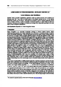
increase in the magnetic flux leakage and not a parametric change of the mutual induction coefficients. However, the consequence of creating a stator phase unbalance originates an anomaly in the distribution of the magnetomotive force and thus the appearance of a negative component system in the stator currents, reflecting the behavior of simulated fault. In the previous theoretical study, the appearance of a negative component system in the stator current comes from the e.m.f.’s (12) induced at the stator when there is a stator unbalanced condition. The application of symmetrical components shows in (13) the referred negative component. Table 4 lists the results obtained without and with stator fault in the synchronous generator. Observe in this table that current amplitudes have been significantly changed due to the fault condition. This result illustrates what has been previewed before in Eq. (13), that the positive component would correspond to only a change of the stator current amplitudes relative to the normal condition of the machine. All our experimental tests were planned to distinguish a normal generator operation from a fault condition in its stator circuits. Therefore, the stator currents evolution was recorded for further analysis, particularly calculating its frequency spectrum and its components in αβ and dq referentials. Fig. 2 shows the stator and rotor currents during normal and stator fault condition.The results in Fig. 2(a) for normal condition shows that even an electrical machine in this situation already presents a three-phase unbalanced situation due to constructive asymmetries, besides the power network not be optimal by introducing harmonics into the electrical machine. These effects will appear reflected in the synchronous generator by the emergence of a negative system that can make difficult the fault diagnosis. Results in Fig. 2(b) show that in case of a stator fault, the original unbalanced condition becomes accentuated, being reflected in the stator currents amplitude. Additionally, fault results in Fig. 2(b) also show that the rotor current presents a ripple due to the stator fault which, despite being an incipient fault,it is sufficient to induce a double frequency component in the rotor current, as also previewed in our analytical
Progress In Electromagnetics Research B, Vol. 39, 2012 2.5
2.5 It
2.0
1.5
1.5
1.0
1.0
Currents [A]
Currents [A]
It
Ir
Is
2.0
0.5 0
Ir
173
Iexci t
-0.5 -1.0 -1.5
Is
0.5 Iexcit
0 -0.5 -1.0 -1.5
-2.0
-2.0
-2.5 -0.02
-0.015
-0.01
0
-0.005
0.005
0.01
0.015
0.02
-2.5 -0.02
-0.015
-0.01
0
-0.005
0.005
Time [s]
Time [s]
(a)
(b)
0.01
0.015
0.02
Figure 2. Stator currents in the synchronous generator and its rotor current. (a) Without stator fault. (b) With stator fault.
f
f = 50 Hz
= 50 Hz
f
f = 250 Hz f = 350 Hz f = 150 Hz
(a)
= 150 Hz f
= 250 Hz f
= 350 Hz
(b)
Figure 3. Frequency spectrum of the stator currents. (a) Without fault. (b) With fault. results by Eq. (12). Frequency spectrum of the stator currents,without and with the stator fault, is shown in Fig. 3. Both spectra show the 50 Hz from power network and also the 5th and 7th harmonics introduced by power network that supplies the synchronous machine. A 3rd harmonic appears even in normal condition caused by the inherent asymmetries of the synchronous generator, as previewed in the theoretical study in Eq. (20), namely that of the d and q axis subtransient reactances be different, as listed in Table 3. When a fault occurs in the stator circuits, the stator currents are modified due to a strong presence of a negative component. This also results in a substantial increase of each current magnitude due to impedance (21) that acquires a low value, and also
174
Dente and Branco
f = 100 Hz f = 200 Hz
(a)
(b)
Figure 4. Frequency spectrum of the field current. (a) Without fault. (b) With fault. occurs a significant increase in the amplitude of the 3rd harmonic, as shown in Fig. 3(b). This remark can be confirmed again by Eq. (20) from the theoretical results. When a stator parametric change occurs due to a fault, it originates an e.m.f. that creates an unbalanced system and thus the appearance of an inverse magnetic field. In this case, the stator currents amplitude increase either in the ω and 3ω angular frequency components. Notice that this information will ensure a stator fault diagnosis by comparing the frequency spectrum before and after the fault. Looking now to the frequency spectrum of field current in the synchronous machine, it confirms the appearance of a 2nd harmonic visible in Fig. 4(b), which is the spectrum for a fault condition, and must be compared with the spectrum at normal condition shown in Fig. 4(a). The 2nd harmonic magnitude emerges due to the presence of a negative component that has an angular velocity (ω) equal to the rotating field but with opposite rotation. Since the rotor is stationary relatively to the rotating field, the negative component appears in the rotor as a 2nd harmonic (2ω). Also, it can be verified the appearance of a 4th harmonic because the 3rd one circulating in the stator contains a negative component. 4.2. Stator Fault: Feature Extraction One fault detection methodology adapted from that generally used for induction machines and described in [6, 7] was considered by us. This methodology uses the Cartesian reference and also the αβ and dq0 vector coordinates by reading two stator currents in
Progress In Electromagnetics Research B, Vol. 39, 2012
175
order to understand the evolution of those electrical quantities, hence evaluating the fault magnitude and its possible detection using those referentials. Analyzing the αβ stator currents without and with stator fault as shown in Fig. 5. Fig. 5(b) shows when compared with Fig. 5(a) that in case of fault a modification occurs not only on current amplitudes but also a modification occurs in their phase displacement. Of course that in an ideal situation, these two components would be in quadrature and had equal amplitude. If they are represented in a vector image, the shape expected to an ideal non-fault situation will be a perfect circle centered at the origin. However, the synchronous machine in terms of construction is already slightly asymmetric due to the rotor not be a completely symmetrical structure, with only symmetry about the d and q axes. This effect can be visualized in Fig. 6 though the slightly deformed circumference represented by the solid line. However, when there is a fault, Fig. 6 shows that the circle changes its shape for an ellipse (dotted line) due to a clear change in αβ stator current amplitudes and phase, reflecting the presence of a negative component caused by the stator fault. A second and more practical methodology for fault detection uses the rotor dq0 referential. By analyzing the evolution of dq stator components in a normal condition, it is expected that the dq representation be constant in time. In reality, this not happens because there are unbalances in the three-phase system of the power network, as well as asymmetries in the electric machine. Fig. 7 illustrates the dq currents (solid line) for the case where the generator is considered working in a normal condition. However, the stator fault unbalance Co rren t es χ - δ
Corr en tes χ -δ
3.0
3.0
Iα
Iβ 2.0
2.0
1.0
i α , i β [A]
i α , i β [A]
Iα
Iβ
0
-1.0
1.0
0
-1.0
-2.0
-2.0
-3.0 0.005
0.01
0.015
0.02
0
0.03
0.01 0.015
0.02
-3.0
0.005
0.01
0.015
0.02
0
0.03
Time [s]
Time [s]
(a)
(b)
0.01
0.015 0.02
Figure 5. The αβ stator currents. (a) Without stator fault. (b) With stator fault.
176
Dente and Branco 33
4.0
22
iq
3.0
11
00
i d , i q [A]
i β [Α]
2.0
-1- 1
1.0
id Id
0 -1.0
-2.0
-2- 2 -3.0
-3- 3 -3 -3
--2 2
-1 -1
1
00
22
-4.0
33
0
0.005
0.01
0.015
0.02
i α [Α]
0.025
0.03
0.035
0.04
0.045
Time [s]
Figure 6. Vector representation of the αβ stator currents: Without stator fault (solid line); with stator fault (dotted line).
Figure 7. Representation of the dq stator currents: Without stator fault (solid line); with stator fault (dotted line).
1.0 0.9
Magnitude [Hz]
0.8 0.7
100 Hz
0.6 0.5 0.4 0.3 0.2 0.1 0.0
0
50
100
150
20 0
25 0
300
350
400
Freq [Hz]
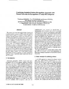
Figure 8. Frequency spectrum of dq stator currents: Without stator fault (solid line); with stator fault (dotted line). causes the appearance of an inverse system in the rotating magnetic field, which affects the dq0 currents and originates a double frequency oscillation superposed on dq (dotted line) currents, as shown in Fig. 7. Notice that this is a good fault indicator, which provides an additional perspective to the fault analysis in its early stage. Frequency spectrum of the dq components in Fig. 8 shows that oscillation in both components is manifested as an increase of the 2nd harmonic. Hence, we have now another comparison technique for detection of incipient stator faults in a salient-pole synchronous generator. The option is still to represent the dq variables in the D’Arganplan to verify if it is possible to distinguish between a normal
Progress In Electromagnetics Research B, Vol. 39, 2012 Component dq0 4
3
3
2
2
1
1
i q [A]
i q [A]
Co mpo nent e dq0
4
0
0
-1
-1
-2
-2
-3
-3
-4
-4 -4
-3
-2
-1
0
177
1
2
3
4
0
-4
-3
-2
-1
0
i d [A]
i d [A]
(a)
(b)
1
2
3
4
Figure 9. Vector representation of thedq stator currents. (a) Without stator fault. (b) With stator fault. from an incipient fault condition. For example, Fig. 9(a) shows an almost point shape when the generator operates without fault. This shape happens because the dq signals are roughly constant over time. On the contrary, Fig. 9(b) shows the fault situation characterized by an ellipse shape. The ellipse will be greater the larger the fault, i.e., the larger the phase shift and amplitude difference between dq components. 5. CONCLUSION In this paper, faults in the stator circuits of salient-pole synchronous generator were theoretically modeled and analyzed. The analytical methodology used provided us with the main characteristics in the frequency spectrum of stator currents that indicate the appearance of incipient stator faults. It was shown that fault in stator circuits increase stator currents magnitude,stator currents become unbalanced, and these also affects the rotor currents by superposition of a 2nd harmonic component. Based on those theoretical results, a simple pattern recognition technique, adapted from previous induction machines’ results, was applied to the incipient stator fault detection of the salient-pole synchronous generator. That methodology, although not new, was applied for the first time in salient-pole synchronous generators for incipient faults detection. Through a set of experimental tests, this methodology showed its simplicity and effectiveness as a proper fault detection methodology, including its degree.
178
Dente and Branco
REFERENCES 1. Yang, W., “Condition monitoring and fault diagnosis of a wind turbine synchronous generator drive train,” IET Renewable Power Generation, Vol. 3, No. 2, 630–636, 2009. 2. Faiz, J., B. M. Ebrahimi, M. Valavi, and H. A. Toliyat, “Mixed eccentricity fault diagnosis in salient-pole synchronous generator using modified winding function method,” Progress In Electromagnetics Research B, Vol. 11, 155–172, 2009. 3. Hadef, M., M. R. Mekideche, A. Djerdir, and A. Miraoui, “An inverse problem approach for parameter estimation of interior permanent magnet synchronous motor,” Progress In Electromagnetics Research B, Vol. 31, 15–28, 2011. 4. Yaghobi, H., H. R. Mashhadi, and K. Ansari, “Artificial neural network approach for locating internal faults in salientpole synchronous generator,” Expert Systems with Applications, Vol. 38, No. 10, 13328–13341, 2011. 5. Karrari, M. and O. P. Malik, “Identification of synchronous generators using adaptive wavelet networks,” Int. Journal of Electrical Power & Energy Systems, Vol. 27, No. 2, 113–120, 2005. 6. Faiz, J. and B. M. Ebrahimi, “Mixed fault diagnosis in three-phase squirrel-cage induction motor using analysis of air-gap magnetic field,” Progress In Electromagnetics Research, Vol. 64, 239–255, 2006. 7. Cardoso, A. J. M. and E. S. Saraiva, “Computer-aided detection of airgap eccentricity in operating three-phase induction motors by Park’s vector approach,” IEEE Trans. on Industry Applications, Vol. 29, No. 5, 897–901, 1993.