Abstract-This communication presents a remote-controlled power switch for extending the battery life of biomedical instruments im- planted into animals or ...
858
I E E E TRANSACTIONS O N BIOMEDICAL E N G I N E E R I N G . VOL 36. NO. X. A U G U S T I Y X Y
upon aperiodic stimuli,” IEEE Trans. Biorned. E n g . , vol. BME-12, pp. 87-94, 1965. [3] S . Abboud, R. Belhassen, S . Laniado, and D. Sadeh, “Noninvasive recording of late ventricular activity using an advanced method in patients with a damaged mass of ventricular tissue,” J . Electrocard., vol. 16,110. 3 , p p . 2 4 5 - 2 5 2 , 1983. 141 E. J. Berbari, B . J. Scherlag, N. El-Sherif, B. Befeler, J . M. Aranda, and R. Lazzara, “The His-Purkinje electrocardiogram in man. An initial assessment and its uses and limitations,” Circulation, vol. 54, no. 2 , pp. 219-224, 1976. [ 5 ] M. B. Simson, “Use of signals in the terminal QRScomplex to identify patients with ventricular tachycardia after myocardial infarction,” Circulation, vol. 64, no. 2, pp. 235-242, 1981. [6] S . Haykin, Communicurion Systems 2nd ed. New York: Wiley, 1983. [7] G . M. Jenkins and D. G . Watts, Spectral Analysis andirs Applicarions. Oakland, CA: Holden-Day, 1968. [8] 0. Rompelman, “Accuracy aspects in ECG-preprocessing for the study of heart-rate variability,” in The Bear-by-beat Invesrigation of Cardiovascular Function, Measurement, Analysis, and Applications, R. I . Kitney and 0. Rompelman, Eds. Oxford: Clarendon, 1987, pp. 103125.
A Simple Remote-Controlled Power Switch for Internalized Bioelectronic Instrumentation S . M. VAROSI, R. L. BRIGMON,
AND
E. L. BESCH
Abstract-This communication presents a remote-controlled power switch for extending the battery life of biomedical instruments implanted into animals or humans. The switching action is controlled externally to the implant by an inductive link between two coils, one contained in the implant and one external to the implant. The external coil sends an electromagnetic pulse to the implant, triggering a CMOS “D” flip-flop connected as a toggle switch-its state is toggled on or off upon receiving the external pulse. The standby current drain of the switch is about 4 nA. The remote triggering range is approximately 20-50 cm. Testing of the switch, surgically implanted as part of a telemetry transmitter, is also discussed.
I . INTRODUCTION Energy sources for implantable bioelectronic sensors and systems are important and are often the limiting factor in research projects involving animals. The most common energy sources include nonrechargeable batteries and inductively coupled RF power links used either solely or in conjunction with rechargeable batteries [ I ] . Because of the short lifetime of nonrechargeable batteries, their usefulness is limited, particularly in long-term (e.g., aging) studies. On the other hand, inductive power coupling offers virtually unlimited implant lifetime but it is difficult to implement and the coupling range is very limited. Remote power control of implanted electronics, therefore, has been utilized to extend the nonrechargeable battery lifetime. Of the several different types of remotely controlled switches developed in recent years, the simplest is a bistable magnetic reed switch connected in series with the battery [2]. The switch can be activated by passing a permanent magnet over the implant. Nonetheless, the usefulness of this type of switch is limited because the remote power control must be placed near the animal and the exact orientation of Manusript received August 26, 1988; revised January 9 , 1989. The authors are with the Department of Physiological Sciences. College of Veterinary Medicine, University of Florida, Gainesville, FL 32610. IEEE Log Number 8928354.
the implant is often not known. One advantage of this procedure is that it requires zero standby power. The preferred method for range and ease of switching is the socalled command receiver [3]-[6]. The command receiver, incorporated into the implant, receives and interprets an RF signal to turn the power on or off. This scheme uses a coil-capacitor tank circuit to detect the external RF command signal, followed by active (powered) amplification and latching circuitry to perform switching. Because command receivers have active circuitry, they can be actuated from considerable distances ( I O cm-15 m ) depending on power drain allowed. Unfortunately, the complexity of the amplification and latching circuitry in most of these designs [3]-15) necessitates the use of integrated circuit techniques. The remotely controlled switch described herein is an intermediate between the above alternatives (reed switch and RF command receiver) both in simplicity and in remote triggering range. The design is unique in that the triggering signal is a single electromagnetic pulse and no amplification of the pulse is needed in the remote receiver, greatly reducing the number of components required. Although this type of “passive” reception decreases the remote triggering range, its simplicity allows construction without special IC fabrication techniques. 11. C I R C U I DESCRIPTION T
Remote Controlled Power Switch
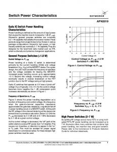
The circuit of the remote controlled switch interrupts or connects power to any low power device, in this case, a temperature telemetry transmitter (Fig. 1). Batteries B1 and B 2 , connected in series, supply 3 V to the circuit. The circuit is triggered by an electromagnetic pulse generator (pulser). TMOS transistor Q l does the actual switching of power. When the voltage at gate G of Ql is above 2 V , the transistor turns on and completes the current path for the transmitter (or other device). The gate voltage for Ql is supplied by the Q logic output of IC1 which is a CMOS “D” flipflop connected as a toggle flip-flop. This means that the output changes logic level when a positive edge clock pulse is introduced at the clock input CLK. The toggling action of the flip-flop, coupled to the current switching action of Q l , provides the on/off power switching of the transmitter. The pulse toggles the flip-flop to the desired state. Because IC1 requires a minimum of 3 V to function and the transmitter used here requires 1.5 V, it was necessary to introduce TMOS transistor Q l to switch current. Ql and MB1 can be eliminated, however, if IC1 and the transmitter (or other device) can use the same battery (3-16 V)-the Q ( o r Q ) logic output of IC1 can supply power to the transmitter directly as shown by the alternate connection [dotted TX box, Fig. I(a)]. Remote control of the transmitter power switch is accomplished by inductive electromagnetic coupling. Coil L1 consists of 400 turns of 36 AWG magnet wire and acts as a receiver of electromagnetic pulses from the pulser. The current pulse generated in coil L2 of the pulser induces a current in coil L1 of the remote switch; the induced current pulse acts as a clock signal for IC 1. Because of the MOS gate capacitance CG present at the clock input CLK of IC I , the voltage at CLK has a tendency to oscillate. This oscillation may cause undesirable multiple triggers of the flip-flop and therefore uncertainty as to whether the switch is on or off. The oscillation is eliminated by adding diode D1 in the current path which allows only a single voltage pulse to be generated at the clock input CLK. The threshold clock voltage of IC1 is 1.7 V at Vdd = 3 V . One leg of L1 is connected to the 1.5 V tap between BI and B 2 to effectively reduce the clock threshold voltage of IC1 to about 0 . 2 V, and thereby increase the triggering range of the switch. Note that if the one battery alternate connection mentioned above is used, a tap of appropriate voltage, if not already available, needs to be provided to maintain increased range.
0018-929418910800-0858$01.OO 0 1989 IEEE
e
859
IEEE TRANSACTIONS ON BlOMEDICAL ENGINEERING. VOL. 36. N O . X. AUGUST 19x9 To col1 L 1
IC1, D FLIP-FLOP
TtLLYmY
nJ
AD1
-
I--
T
1POVAC
LT
sw 1
R1
(b) Fig. 1. Circuit diagrams. (a) Remote controlled switch. (b) Remote triggering circuit (pulser). A current pulse in L 2 induces the trigger signal in L1.
TABLE I COMPONENT VALUES FOR T H E REMOTE SWITCH A N D PULSER Remote Switch IC 1 Ql B1,B2 L1
D1
Motorola MC14013BCP dual D flip-flop Motorola BSI70 TMOS mosfet Eveready 364 1.5 V silver-oxide cell 400 turns of 36 AWG magnet wire on a 1.6 cm diameter cylindrical vial 1N9 14 small signal diode
‘coil L 1
‘Plastic
Vial, 5 / 8 ’ Dia
(C) Pulser
c1, c2, c 3 c4 D2,D3 RI R2 R3 L2
sw 1 SCR
1.O pF, 600 V 10 IF, 16 V electrolytic I A , 400 PIV silicon diode 220 kR, 1 / 2 W 3.3 kR, 1 / 2 W 1 kfl, 1/2W 1 turn of 12 AWG solid insulated wire, 15 cm diam Pushbutton switch NEC 8193 6 A, 400 V
Electromagnetic Pulse Generator (Pulser)
The pulser circuitry consists of a high voltage capacitor that supplies a brief current pulse through a single loop coil L2, creating an electromagnetic pulse in the surrounding place [Fig. l(b)]. Capacitor C1 is charged by a voltage doubler powered from a 120VAC outlet. Switch SW1 is closed causing the SCR to fire thus discharging C 1 into L2 generating the pulse. The voltage divider ( R 1 and R 2 ) charges C4 to about 2 V. When SW1 is manually depressed, C4 discharges (triggering the SCR) and remains discharged until SW 1 is released thereby ensuring that the SCR fires only once when SW 1 is depressed.
Fig. 2 . Switch construction with discrete components. (a) Top view connections. (b) Side view with battery and transmitter connections. (c) Completed transmitter/switch is placed inside a cylindrical plastic vial such that RFCl is at the closed end and MBl is at the open end. Coil L1 has been wound on the exterior of the vial.
Construction
Component values for the remote switch and pulser are given in Table I . Details of construction (Fig. 2) can vary with application and component layout is not critical. Miniaturization by hybrid IC techniques may be a layout option (IC1 and Q 1 can be obtained without bulky epoxy cases) for some future applications. The FM transmitter which relays temperature information to a computer is built on a printed circuit board and is self-contained except for the 1.35 V mercury battery MB1. The RF coil of the transmitter RFCl and the receiving coil of the remote switch L1 are at opposite ends of a completed transmittedswitch [Fig. 2(c)] to minimize the effect of L1 on FM transmission. Range of Remote Contorl
The range of remote control depends on the relative orientation of coils L1 and L2. If the two coils are positioned on axis (maxi-
860
IEEE TRANSACTIONS ON BIOMEDICAL ENGINEERING. VOL. 36. NO. 8. AUGUST 19x9
mum flux linkage), the switch can be triggered from 50 cm. When the center to center distance between the two coils is 2 0 cm or less, triggering is possible from any orientation. The geometry and number of turns of L1 can be modified to meet specific size or range requirements. The area of L1 should be kept as large as possible. The number of turns should be about 100-500 for most applications (however, a bulky coil may affect telemetry transmitter signal strength). 111. APPLICATION Five completed remote-controlled switches interconnected with FM temperature transmitters [7] were encapsulated in beeswax and tested for remote switching capability. After surgical implantation into each of five rabbits with the switch in the off state, each unit was switched on with the pulser when data from the telemetry transmitter was desired. The rabbits were housed in an environmental chamber kept at 24°C and 50 percent relative humidity on a 12 h light dark period (light on from 0800 to 2000). Body temperature data for three days, collected every 5 min and averaged each hour, were not significantly different for two separate weekly periods. The transmitters were turned off for ten days between data acquisition periods to extend battery life and test reliability and effectiveness of the switch. Consistent and repeatable data were collected for one year from five animals. During that period, none of the transmitters failed prematurely or failed to response to an on/ off command. Furthermore, no false triggering of any of the implanted remote switches was observed. Prior to using the switch, the batteries in these transmitters lasted 6-8 weeks. Incorporating the switch does not alter performance of the telemetry transmitter after repeated use.
IV. DISCUSSION The implant circuit described here can be fabricated using only four discrete components and two batteries; if the transmitter operates on 3 to 16 V , Q l and one battery can be eliminated. Also, although more complex circuits [3]-[5] may have a greater triggering range, the circuit described here has comparable reliability in terms of immunity to false triggering and more reliability in terms of component failure. The probability of a false trigger is very low when the switch is more than 30 cm away from EM noise sources (air conditioners, heaters), and no such occurrence has been logged to date. This remote switch draws about 4 nA standby current which is less than that of any previous design noted [3]-[6]. An implanted device could be left on standby for possibly 3-5 years, although this claim has not been verified. V . CONCLUSIONS Although various circuit designs for remote-controlled power switches are available to researchers, the one described here provides an economical, reliable, and easily fabricated alternative method of implant activation or deactivation. It should be kept in mind that greater sensitivity to a triggering signal implies greater complexity and most often a larger current draw. The triggering signal receiver and power switch circuit must draw far less power than does the device it is switching for the switch to aid in extending battery life. The passive nature of the receiveriswitch disclosed herein bypasses that design problem. The switch has proved successful in lab animal environmental research and future projects are being planned by other researchers to further test its operation and lifetime.
ACKNOWLEDGMENT The contributions of G . R . Duensing and C . E. Bucher of the Department of Electrical Engineering, University of Florida, and the College of Veterinary Medicine, University of Florida Journal Series no. 170, are gratefully acknowledged.
REFERENCES J . D. Meindl and A. I. Ford, “Implantable telemetry in biomedical research,” lEEE Trans. Biomed. Eng., vol. BME-31, pp. 817-823, Dec. 1984. J . C. Coggshall et a / . , “Control of biomedical implants by dc magnetic fields,” Proc. 19th Annu. Con$ Eng. Med. B i d . , vol. 8, p. 121, 1966. H. V. Allen, J . W . Knutti, and J . D. Meindl, “Integrated powercontrollers and RF data transmitters for totally implantable telemetry,” Biotelemetry Patient Monitoring, vol. 6 , pp. 147-159, 1979. H. V . Allen and J . W . Knutti, “A fully integrated RF activated battery controller,” / € € E Int. Solid-State Circuits Con$ Dig., vol. ISSCC 81, pp. 166-167, 1981. A. S . Santic, S . Vamvakas, and M . R. Neuman, “Micropower electronic switches for implanted instrumentation,” / E € € Trans. Biomed. Eng., vol. BME-29, pp. 583-589. Aug. 1982. J . D. Sweeny, A. Leung, and W . H. KO, “An implantable micropower command receiver for telemetry battery power switching,” Bioteleme t r y Patient Monitoring, vol. 8, pp. 173-179, 1981. H . Kadono and E. Usami, “Circadian rhythm and egg formation in the domestic fowl monitored by telemetric measurement of deep body temvol. 5 , pp. 21 1-214, 1980. perature,” Biotelemetr~~,
Microcomputer-Based Interactive Tracking of Blood Cells at Biomaterial Surfaces DAVID W. CAPSON, RICHARD A. MALUDZINSKI, IRWIN A . FEUERSTEIN
AND
Abstract-A microcomputer-based system for analyzing the motion of human platelets and leukocytes at synthetic surfaces from a sequence of video frames on tape is described. The software is designed to provide convenient interaction with an operator to reduce the burden of manual analysis. In addition, the system computes and stores the cell movement data on disk for subsequent statistical analysis. Measurements include the number and nature of cell-to-surface collisions, residence times, and distances traveled.
I. INTRODUCTION Blood contact with nonbiological surfaces now occurs in a variety of situations including 1) blood processing, often part of fractionation for specific components, 2) treatment protocols such as those for the artificial kidney, and 3) replacement of arterial segments with polymeric materials. When blood is returned to a patient after being in contact with a nonbiological surface it may be depleted of cells and proteins o r they may now be in an altered state where function is compromised. Several volumes dealing with the above are 111-[3]. The evaluation of materials for blood compatibility has been done in three major experimental areas: 1) In vivo-where an animal is placed ih a closed circuit [4], [SI. 2) In vitro-where anticoagulated blood is taken from an animal and contacted with a material in a bench-top experiment [6], [7]. Manuscript received September 16, 1988; revised January 26, 1989. This work was supported by the Natural Sciences and Engineering Research Council of Canada and the Heart and Stroke Foundation of Ontario. D. W . Capson and R. A. Maludzinski are with the Department of Electrical and Computer Engineering, McMaster University, Hamilton, Ont., Canada L8S 4L7. 1. A . Feuerstein is with the Departments of Chemical Engineering and Pathology, McMaster University, Hamilton, Ont., Canada L8S 4L7. IEEE Log Number 8928355.
001 8-9294/89/0800-0860$01.OO 0 1989 IEEE