Abstract. UML Profiles allow designers to customize the UML to their .... In this section, we take into account the limitations explained above to propose a general ..... MDA Guide Versión 1.0.1â, http://www.omg.org/docs/omg/03-06-01.pdf.
A simple yet useful approach to implementing UML Profiles in current CASE tools Jordi Cabot, Cristina Gómez Universitat Politècnica de Catalunya Dept. Llenguatges i Sistemes Informàtics Jordi Girona 1-3, 08034 Barcelona (Catalonia) e-mail: [jcabot|cristina]@lsi.upc.es Abstract. UML Profiles allow designers to customize the UML to their particular domain or purpose. Moreover, they play an important role in MDA. These profiles must be implemented in the CASE tools the designer employs to gain the benefits of their use. This paper identifies the limitations of current CASE tools with respect to profile definitions and presents an approach that overcomes them. The basic idea of our method is to extend the CASE tool with a set of profile operations that act as an interface with designers when they want to use the elements of the profile in their models.
1. Introduction Since its inception, UML has intended to cover as many domains as possible. That is the reason why it provides some extension mechanisms, as are: stereotypes, tagged definitions and constraints [OMG01, 2-191]. These mechanisms allow the designers to customize the UML to their particular domain or purpose. A coherent set of such extensions constitutes an UML Profile. More recently, the concept of profile has been paid much attention due to its importance in the context of the Model Driven Architecture [OMG03a]. MDA is aimed at generating automatically (or semi-automatically) implementation models (i.e. platform specific models, PSM) of a system in multiple platforms. This is done by applying mappings to the specification system models (i.e. platform independent models, PIM). These mappings may be prepared and specified using UML Profiles [OMG03a, p. 4-2]. There are profiles that have already been standardized (or are in process) by the OMG (see [OMG03b]). Some CASE tools have incorporated these standard profiles, which allow their users to take profit of them in their models. However, other profiles, which are not standardized, cannot be used because the majority of tools do not incorporate them. Moreover, tools neither completely support new profiles definition. This dramatically reduces the advantages that could be gained from the use of profiles. In fact, the proliferation of a huge amount of profiles has not been accompanied by the necessary support of existing CASE tools.
-1-
The main goal of this paper is twofold. On the one hand, it identifies the limitations of CASE tools when a profile implementation is considered. On the other hand, it proposes an approach to avoid these limitations by extending current CASE tools, in order to allow designers to define, implement and use the profiles in their models. This approach has been applied in the implementation of the Partition Profile ([GóOl02], [CaGó02]). The rest of this paper is organized as follows. Section 2 reviews the concept of profile and defines the Presentation profile that will be used as an example throughout the paper. Section 3 focuses on the limitations of CASE tools when a profile implementation is considered. In Section 4, we propose an approach to overcome them. This approach is applied to the Presentation profile. Section 5 describes an implementation of the proposed approach. Moreover, Section 6 presents a comparison with other possible approaches. Finally, last section remarks some conclusions and points out future work.
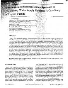
2. UML Profiles An UML Profile is a package that contains model elements that have been customized for a specific domain or purpose using extension mechanisms, such as stereotypes, tagged definitions and constraints [OMG01, 2-191]. A stereotype provides a way of defining virtual subclasses of UML metaclasses with additional semantics. It can define additional constraints over its base metamodel class as well as tags to define additional properties. A constraint is a semantic restriction represented as a text expression. Constraints are attached to one or more model elements. They are usually specified using the OCL (Object Constraint Language) [OMG01, Chapter 6]. Tags definitions specify new kinds of properties as part of a stereotype definition. The actual properties of individual model elements are specified using tagged values. Stereotypes and tags definitions can be derived. This means that they can be computed from other elements by means of a derivation rule. The derivation rule can be written in OCL as a constraint [RuJB99]. Figure 1 presents the Presentation profile, an UML profile that will be used as an example throughout the paper. The purpose of this profile is to describe the presentation model of an application. Specifically, it aims at the design of its graphical user interface (GUI). Note that it is not the goal of this paper to define a complete presentation profile. We only use it as a running examp le. The basic concepts of this profile are mainly taken of [HeKo01, Cona99]. We assume that a GUI consists only of forms and two types of controls: edit boxes and buttons. A form is used to introduce and visualize data of an information system. It may contain edit boxes and buttons and may display other forms. The Form stereotype represents the forms that appear in a GUI. The base tags represent the width and
-2-
height of the forms. Moreover, this stereotype has the derived tag ndisplayedforms that represents the number of forms that can be accessed and displayed by the form. P r e s e n t a t i o n Profile Class
Association
Form width:Integer height:Integer /n d i s p l a y e d f o r m s : I n t e g e r
Control
Displays Contains
coordinatex:Integer coordinatey:Integer
Button EditBox type:ButtonType
ButtonType Close Accept Cancel
Figure 1: The Presentation profile
The Control stereotype represents the controls that appear in forms. This stereotype is abstract, and it is used only to define two common tags: coordinatex and coordinatey. These tags represent the coordinates x and y of the control inside the form. The binary relationship of containment between forms and the controls placed inside is specified by means of an association with the Contains stereotype. A single instance of a class with the EditBox stereotype represents an edit box control of a form, while a class with the Button stereotype represents a button control. Its tag type indicates if the button is an accept, close or cancel button. The relationship between two forms where one of them (source) displays the other (destination) is specified by means of an association with the Displays stereotype. We use the navigability in the association to distinguish between the source and destination forms. The association can be traversed from the source to the destination form. The profile includes several constraints concerning the stereotypes (their formalization in OCL can be found in [CaGó03]): R01: The height and width of a form must be positive. R02: There cannot exist a cycle of associations with the Displays stereotype. R03: The coordinates x and y of the controls cannot be out of the range of the forms where they are placed inside and must be positive. R04: Associations with the Contains stereotype must have two participants. One of them must be a form and the other must be a control. R05: There cannot be two Contains associations between the same form and control. R06: A Displays association must have two participants. Both participants must be forms. The navigability is single in the direction of the destination form. R07: There cannot be two displays associations between the same forms. R08: The multiplicity of the associations with the Contains and Displays stereotype must be one in both association ends.
-3-
As an example, Figure 2 shows a simple GUI, specified using the Presentation profile, for an application that deletes customers from the information base. This application consists of two forms: SelectCustomer, to select the customer to be deleted, and DeleteCustomer, to delete the chosen customer. In both forms, the user can accept or cancel the action of selecting (deleting) the customer. DeleteCustomer 1 1
acceptDelete
1
1
1
SelectCustomer 1
1
1
1
cancelDelete
acceptSelect
1
cancelSelect
Figure 2: Example of a GUI specified using the Presentation profile
3. Limitations of current CASE tools related to profiles definition Nowadays, it is difficult to imagine that a company that uses the UML notation in the analysis and design of its applications does not employ also a CASE tool to gain the benefits of its use (for instance, round-trip engineering, documentation generation and so on). Therefore, the profiles, to be useful, must be incorporated into the CASE tool the company uses. Although there is a huge amount of different CASE tools (see [Jeck03] for an exhaustive list), most of them share the same features and limitations relating to profiles definition. In the next subsections, we will identify such limitations and describe how they affect the definition of profiles within CASE tools.
3.1 Stereotypes and tags definition Most tools support the concept of stereotype. Therefore, they can be implemented as such on the CASE tool. In fact, if a tool does not allow the definition of new stereotypes, it makes no sense to try to implement UML Profiles, since they are based on the notion of stereotypes. The same happens with the definition of tags in the stereotypes. CASE tools allow the specification of tag definitions over the stereotypes previously created. However, CASE tools do not allow the definition of derived stereotypes or tags. CASE tools do not support the management of derived information, and thus, they are unable to do an automatic computation of the derived tags or stereotypes of the profile. This implies, for example, that the tagged values of the derived tags will be out of date. Applying it to the Presentation profile, this means that specifying that the form f1displays the form f2 would not automatically increase by one the value of the f1 derived tag ndisplayedforms, and thus, the tag would not reflect a correct value.
-4-
3.2 Constraints With stereotypes and tags, we can already specify graphically models that use the profile. However, the constraints of the profile must be defined to ensure that it is correctly used. Most CASE tools are able to verify the constraints defined in the UML metamodel. Thanks to this feature, well-formed models can be specified. For instance, we could not define two attributes with the same name within a class because this violates a well-formedness rule of the Classifier metaclass [OMG01, pp. 2-56]. On the contrary, to the best of our knowledge, none of the present CASE tools is able to enforce the constraints attached to the stereotypes of the profile. Some tools allow their definition (for example [Obje03]) but are unable to interpret them. Few tools like [Argo03] and [USE03] offer an OCL interpreter for checking the syntax of the constraints applied to a model. [USE03] goes even a step forward and allows the designer to create instances of the model to validate the constraints. However, these tools only apply these techniques at the model level but not to the metamodel, and thus, they cannot be used to check the constraints attached to the stereotypes of the profile. Designers specify their models using the operations provided by the tool (for instance, to create a class, to create an association, to assign a stereotype or to add an attribute), usually through a graphical interface. If designers use a profile by using those tool operations and the tool is unable to verify the profile constraints, it cannot be ensured that the resulting model is consistent with them. For example, using the tool operations we could specify a model with a form displaying an edit box, violating rule R06 that states the both participants of a Displays association must be forms .
4. An approach to implementing UML Profiles In this section, we take into account the limitations explained above to propose a general approach to implement profiles in CASE tools to allow designers gain the benefits of a full implementation of their profiles. To avoid the limitations of current CASE tools, we propose to extend these tools with a set of profile operations. These operations act as an interface with the tool user when s/he wants to use some element of the profile in order to ensure the consistency of its use and to compute automatically the derived tags and stereotypes. They will verify that the action the designer asks for is consistent with the profile constraints, before performing it. Moreover, they will be in charge of keep up to date all the derived information affected by the action. In the implementation of these operations, we take profit of the scripting facilities offered by most tools (see, for instance, [Desc03], [Obje03], [Rose03] or [Toge03]). Through scripting, designers may create scripts that can access and modify the models within the tool. To do it, scripts must use the metamodel interface offered by the tool.
-5-
The approach that we propose to implement a UML Profile in a CASE tool consists of five different actions: 1. To define the profile stereotypes and tags in the target CASE tool. 2. To extend the CASE tool with the profile operations. 3. To assign the verification of the profile constraints to the profile operations. 4. To assign the computation of the derived information to the profile operations. 5. To remove the unnecessary operations. To illustrate each of them we will use the Presentation profile.
4.1 Defining the profile stereotypes and tags in the target CASE tool As we have seen in the previous section, CASE tools do not present limitations related to the definition of base stereotypes and tags, and thus, to define them we simply use the functionalities provided by the tool. To deal with derived stereotypes and tags we must materialize them (i.e. declare them as base ones). The profile operations will update their values according to the changes that would be induced by the derivation rules. In our example, we define six stereotypes (Form, Control, Contains, Displays, Button and EditBox) and six tags (width, height, ndisplayedforms, coordinatex, coordinatey and type).
4.2 Extending the CASE tool with the profile operations We create the profile operations by using the scripting language and the metamodel interface offered by the tool. For each concrete stereotype, we must create two operations: one to create new instances of the stereotype (i.e. to create a new instance of the base class of the stereotype and label it with the stereotype) and the other to delete them (i.e. to delete the stereotyped instance). Moreover, for each base tag of the stereotype, we must create another operation to be able to initialize and modify its value. For instance, in our example we must create the following operations: CreateForm, RemoveForm, CreateButton, RemoveButton, CreateEditBox, RemoveEditBox, CreateContains, RemoveContains, CreateDisplays, RemoveDisplays, ModifyWidth, ModifyHeight, ModifyCoordx, ModifyCoordy and ModifyType. Note that there is not any operation to modify the value of the ndisplayedforms tag. This tag was defined as derived in the profile specification. Therefore, the user cannot directly modify its value.
4.3 Assigning the verification of the profile constraints to the profile operations Each profile operation will be in charge of checking the profile constraints that may be violated by the operation execution. Therefore, if the user attempts to execute an operation that would lead to an inconsistent model, the operation would not perform
-6-
any modification over the model. For instance, the operation CreateDisplays may violate the constraints R02, R06 and R07 if the new Displays association introduces a cycle of associations labeled with the Displays stereotype, if any of the participants is not a form or if a Displays association already exists. To avoid this violation, the preconditions of the operation have to check these constraints. If some constraint is about to be violated by the execution of the operation, the operation is rejected and the Displays association is not created.
4.4 Assigning the computation of the derived information to the profile operations The profile operations must ensure that the values of derived elements are up to date. Therefore, if the action performed by an operation affect some derived elements, the operation must calculate the new values of the derived elements, in the same way it would be done by their derivation rules if we were able to define them. We add these calculi to the postconditions of the corresponding operations. For instance, the operation CreateDisplays creates a new Displays association between two forms. The creation of this new association affects the value of the tag ndisplayedforms. Therefore, the postconditions of this operation must guarantee that the value of the source form tag ndisplayedforms has been increased by one.
4.5 Removing the unnecessary operations After assigning the constraints and derivation rules to each profile operation, we may find that some operations do not have any preconditions or postconditions (for example, if the stereotype does not participate in any constraint or derivation rule). In that case, we do not need to implement the operation. Instead, we can use the tool operations for the base class of the stereotype. For instance, the operation RemoveForm does not present any preconditions or postcondition, so, to delete a form it is enough using the tool operation that deletes a class. Figure 3 shows the interaction between the designer and the CASE tool. Once the profile operations have been implemented, designers use the tool operations to specify their models, unless they want to use some of the elements of the profile. In that case, they use the appropriate profile operation (unless it was an unnecessary operation). Note that the profile operations can make use of the tool operations to simplify its implementation. CASE tool tool operations use Designer
profile operations
Figure 3: Interaction between the designer and the CASE tool
-7-
5. Implementing the Presentation profile in a specific CASE tool In this section we show the feasibility of our strategy by implementing the Presentation profile in the Objecteering/UML CASE tool. In fact, our strategy can be used in any CASE tool providing that it allows the definition of stereotypes and tags and the scripting facilities needed to implement the profile operations. When applying the approach to a given CASE tool we must take into account the specific scripting language and metamodel interface offered by the tool. It is worth noting that some times the metamodel interface offered by the tool differs from the UML metamodel, and hence, we will need to adapt the operation code to the tool metamodel. In the following, we show the implementation of the Presentation profile with the Objecteering/UML CASE tool. We have chosen this tool to implement the profile due to its metamodel interface is very similar to the UML metamodel.
5.1 Implementing the Presentation profile in Objecteering/UML First, we must define the stereotypes that form the profile. This is easily done by tool interaction. The only thing to do is to provide all the stereotype information (base class, tags, etc). After the new stereotypes have been defined, we are ready to implement the operations. These operations are implemented using J methods. The J methods are methods attached to a specific metaclass, and executed using an instance of that metaclass. They are written in the J language. The J language is the proprietary tool scripting language. Nevertheless, its “Java-like” syntax makes it easy to use. It presents some interesting features (see [Soft99] for more details) like model handling capacities. Thanks to these features, the J language is perfectly suitable for implementing the profile operations. In fact, everything the designer can achieve through Objecteering/UML UML Modeler can be achieved through programming with the J language. The implementation of the Presentation profile operations using the J language can be found in [CaGó03]. Once the profile operations have been implemented, designers are ready to interact with the CASE tool in order to use them in their models. For example, if the designer wants to create a new Displays association, s/he must invoke the CreateDisplays operation. Figures 4 and 5 show the process of creating a Displays association between two forms previously defined. First (Figure 4), we select the source form and execute the operation. Then (Figure 5), the designer through a dialog box provides the name of the destination form. The result is shown in Figure 6. Note that, as a consequence of the operation execution the ndisplayedforms tagged value has been increased by one.
-8-
Figure 4: Creating a displays association
Figure 5: Selecting the destination form
Figure 6: Result of the CreateDisplays operation
-9-
6. Alternative approaches Instead of preventing an incorrect use of the profile by means of the profile operations, we could let the designer use the profile using the tool operations and, after, verify if the model is consistent with respect to the profile constraints. We see, at least, two different ways of implementing this delayed consistency check. We could either done it by developing a single profile operation in the tool in charge of checking all the profile constraints, or by exporting the model to a XMI document (XML Metadata Interchange, [OMG02]) and then, analyzing the resulting XMI file by means of some kind of application able to interpret its content and to check the profile constraints. This latter process is sketched in Figure 7. XMI is an interchange format for metadata that is defined in terms of the Meta Object Facility (MOF) standard [OMG02, pp. 1-2]. As shown in [Jeck03], there exist already some tools that offer the possibility of importing and exporting a model into an XMI document. The main advantage of this approach is that, since XMI is a standard specification, we should be able to use a single application to check XMI models generated by any CASE tool. This application could take profit of some OCL interpreters already developed. Of a significant importance is [OCLE03] an object constraint language evaluator able to import an XMI model and ensure that verifies the constraints previously defined in the tool. Unfortunately, nowadays, the XMI documents generated by most tools present some differences from the XMI standard and are seldom interchangeable. Therefore, we will be forced to develop a different checking application for each tool we want to use. The major drawback of both alternatives is that the designer may be using an inconsistent model during a period, until s/he checks it. Moreover, in general, the possible model errors cannot be corrected automatically, so the designer would be responsible of fixing them (and repeating the process to ensure that s/he has fixed the errors correctly). Notice, also, that the above alternatives are unable to deal with derived elements. CASE tool XMI
Checking Application
tool operations OCL constraints
Designer
M o d e l errors information
Figure 7: Delayed checking of the model consistency using XMI
7. Conclusions and further work This paper describes an approach to implement UML Profiles in current UML CASE tools. During the process, we have sketched the limitations of the CASE tools with
- 10 -
respect to profiles definition, especially when dealing with the constraints and derived elements of the profile. To avoid them, the rationale of our method is to extend the CASE tool with a set of profile operations that prevent us from an incorrect use of the profile and that update the derived information. Although we do not deal with them in this paper, the profile operations could also be useful to generate the semantic constraints used in the formal definition of domain-specific stereotypes [Gogo01]. We may conclude that, relating to profile definitions, CASE tools still lack of maturity. In fact, the significant importance of profiles in conceptual modeling and in the successful adoption of the MDA has not been accompanied by the necessary support of existing tools. As a further work, we would like to advance in the automation of our approach, developing a tool that, given a profile definition as input generates, partially, the code of the operations needed to implement the profile in a specific CASE tool.
References [Argo03]
ArgoUML, http://argouml.tigris.org/, visited June 2003.
[CaGó03] Cabot, J.; Gómez, C. “A simple yet useful approach to implementing UML Profiles in CASE tools (Extended Version)”, Report LSI, LSI-03-13-R, UPC, 2003. [CaGó02] Cabot, J.; Gómez, C. “Design and Implementation of Partition profile – An experience report”, Report LSI, LSI-02-70-R, UPC, 2002. [Cona99] Conallen, J; “Modeling Web Application with UML” http://www.conallen.com/whitepapers/webapps/ModelingWebApplications.htm [Desc03]
Describe. http://www.embarcadero.com/products/describe/index.asp, visited August 2003
[Gogo01] Gogolla, M. “Using OCL for Defining Precise,Domain-Specific UML Stereotypes”, In Proc 6th Australian Workshop on Requirement Engineering (AWRE’2001), UNSW Printer Room. [GóOl02] Gómez, C; Olivé, A. “Evolving Partitions in Conceptual Schemas in the UML”, CAiSE’02, LNCS 2348, pp.467-483. [HeKo01] Hennicker, R; Koch, N. “Modeling the User Interface of Web Applications with UML”, UML 2001, LNI 7, pp.158-172. [Jeck03]
Jeckle, M. “UML Tools (Case & Drawing)”, http://www.jeckle.de/umltools.htm, visited June 2003.
[Obje03]
Objecteering/UML. http://www.objecteering.com, visited June 2003.
[OCLE03] Object Constraint Language Evaluator. http://lci.cs.ubbcluj.ro/ocle/, visited June 2003. [OMG01] OMG.“Unified modeling Language Specification”, Version 1.4, September 2001. [OMG02] OMG.“OMG XML Metadata Interchange Specification”, Version 1.2, January 2002.
- 11 -
[OMG03a] OMG.“MDA Guide Versión 1.0.1”, http://www.omg.org/docs/omg/03-06-01.pdf [OMG03b]OMG.http://www.omg.org/technology/documents/modeling_spec_catalog.htm, visited June 2003 [Rose03]
Rational Rose. http://www.rational.com, visited August 2003
[RuJB99] Rumbaugh, J.; Jacobson, I.; Booch, G. "The Unified Modeling Language. Reference Manual", Addison-Wesley. [Soft99]
Softeam; “UML Profiles and the J Language”, White Paper, 1999, http://www.objecteering.com/pdf/whitepapers/us/uml_profiles.pdf, 2003.
visited
June
[Toge03]
Together. http://www.borland.com/together/index.html, visited August 2003
[USE03]
USE. http://www.db.informatik.uni-bremen.de/projects/USE/, visited June 2003.
- 12 -