These technologies include both medium access control (MAC) and physical layer protocols that enable a WPAN to support up to 245 devices operating over an ...
A Simulation Study of the IEEE 802.15.3 MAC Kwan-Wu Chin and Darryn Lowe Telecommunications Information Technology Research Institute University of Wollongong Northfields Avenue, Australia 2522 {kwanwu, darrynl}@uow.edu.au
Abstract— The IEEE 802.15.3 medium access control (MAC) protocol is an emerging standard for high bit-rate wireless personal area networks, specifically for supporting high quality multimedia streams. To date there are no published work on the performance of the IEEE 802.15.3 MAC with respect to some of its configurable parameters and there has been no work related to simulation of the MAC using the popular ns-2 simulator. This paper aims to address the aforementioned shortcomings by presenting an implementation of the IEEE 802.15.3 MAC in the ns-2 simulator and some preliminary results from our studies of the IEEE 802.15.3 MAC in a variety of scenarios with mixed traffic. We present results from our experimentations the impact of the following MAC’s operating parameters on TCP and real-time flows: (i) channel access and time allocation periods, (ii) superframe length, (iii) ACK policies, (iv) size of channel time allocation periods (CTAPs), (v) contention channel access scheme, and (vi) performance of TCP flows when run in the CTAP.
I. I NTRODUCTION The ubiquity of consumer devices with high storage and processing capacity enables the sharing or streaming of different media types, such as digital images and high quality audio/video, from one device to another anywhere, anytime. For example, a user might want to stream movies from his/her personal computer to a highdefinition television (HDTV). To help realize this vision, the IEEE 802.15.3 working group [1] is working on technologies targeted at enabling high-rate multimedia applications operating in a wireless personal area network (WPAN). These technologies include both medium access control (MAC) and physical layer protocols that enable a WPAN to support up to 245 devices operating over an area of at least 10 meters with speeds ranging from 11 to 55 Mb/s. Other features include power saving capabilities, security, and co-existence with interfering networks [2]. To date, little or no published work provides a quantitative measure of IEEE 802.15.3’s performance. Furthermore, to the best of our knowledge, the widely used ns-2 simulator does not implement the IEEE 802.15.3 MAC. Therefore, this paper aims to bridge these gaps by presenting both our implementation of IEEE 802.15.3 in ns-2 as well as some preliminary results obtained from
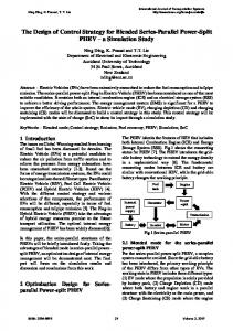
our investigations into the impact of some of the IEEE 802.15.3 MAC operating parameters on the performance of real-time and best-effort traffic. In addition, we also present results concerning the fairness of the MAC’s contention channel access scheme under heavy load and the overheads of various ACK policies. The rest of this paper is structured as follows. Section II presents an overview of the IEEE 802.15.3 MAC followed by a description of our MAC implementation in ns-2 in Section II-B. Section III outlines the IEEE 802.15.3 parameters used in all our simulations. We then present our results in Section IV before giving our conclusion and identifying future work in Section V. II. T HE IEEE 802.15.3 MAC A. Overview The IEEE 802.15.3 MAC protocol [2] uses a master and slave model whereby a master device, called the piconet controller (PNC) controls the piconet. Figure 1 shows an example of a IEEE 802.15.3 piconet that forms part of a home network. The network is formed in an adhoc manner where devices may leave or join the network at any time. Further, the piconet can support different types of traffic. For example, in Figure 1 there are audio and video streams in addition to the best-effort traffic that is transmitted in the contention access period (CAP) of the superframe. A device is elected as the PNC based on a set of criteria which include: its preference for becoming a PNC, whether it is receiving power from the mains, and its ability to act as a security key originator. Once chosen as a PNC, a device’s main responsibility is to coordinate channel access amongst the other devices within a piconet. Other responsibilities include associating and disassociating devices, coordinating wake-up times when in power-save modes, and co-existing with other piconets or networks that share the same wireless spectrum. The PNC coordinates channel access by sending a beacon that marks the start of a superframe. The superframe
MH 1
Node 1
Hi−Fi
Piconet Controller CTAP B CAP
HDTV
HiFi
HDTV
Superframe
Fig. 1. Example of the IEEE 802.15.3 MAC being used to support home devices.
is composed of two periods, namely the CAP and the channel time allocation period (CTAP). Devices in the piconet synchronize with the PNC after receiving the beacon and then transmit in either the CAP or CTAP. To transmit in the CTAP, a device requests CTAs from the PNC by specifying the time units required in order to support its relevant real-time streams. If the PNC grants the device’s request, the device then has exclusive rights to transmit during its CTA slots. Figure 1 shows two CTA slots, belonging to the HDTV and Hi-Fi devices respectively, within the CTAP of the superframe. During its respective CTA slot, each device can immediately transmit any packets it has without having to contend for the channel, thus saving on the overheads and delay associated with channel contention. A piconet can have one or more PNCs in the form of child PNCs. These child PNCs are dependent on the parent PNC to allocate them a CTA slot within which they can send out their respective beacons in order to coordinate channel access between the devices that are associated to them. To become a child PNC, a device requests a private CTA. A private CTA is similar to an ordinary CTA, but has both the source and destination fields of the request set to the requesting device’s address and has a stream index of zero. The IEEE 802.15.3 specification does not specify the level or number of child PNCs that a piconet can have. However, the finite size of the original superframe imposes a practical limit since each child PNC must be allocated time units from its parent PNC’s CTAP for it to be able to create its own beacon.
Ultra Wide-Band (UWB) physical layer developed by the Swiss Federal Institute of Technology [4]. Their physical layer uses pulse position modulation and, at the lowest coding rate, it is able to transmit at 18 Mb/s. Further, this physical layer takes into account interference, bit errors and implements a realistic path loss channel model. The following sections describe our implementation of the IEEE 802.15.3 MAC’s in ns-2. We separate our discussions into two parts: device and PNC. 1) Devices: Association/Disassociation: Before simulation starts, each node is given the PNC’s address and PNCid. Once simulation starts, a device sends an Association Request message to the PNC in the CAP of the superframe. Upon receiving the request, the PNC records the requesting device’s address and assigns it a randomly generated identifier. The PNC then replies to the associating device with an Association Reply message to complete the join process. After associating with a PNC, a device is then able to request CTAs from the PNC by sending the PNC the information shown in Table I. Alternatively, a private CTA can be requested by setting the source and destination address fields to the requesting device’s address and setting the stream index to zero. Parameters Target ID List Stream Request ID
Stream Identifier CTA Type CTA Rate Type
CTA Rate Factor
CTA Rate Time Units Minimum Time Units Desired Time Units
Description A list of devices involved in sending or receiving the stream The ID used to identify the current stream before being allocated an unique piconet-wide stream identifier. A piconet-wide stream identifier assigned by the PNC. Determines whether the requested CTA is pseudo-static Sub-rate or super-rate CTA. Sub-rate CTAs occur once every CTA-rate-factor superframes whereas super-rate CTAs occur every superframe This is used in conjunction with sub-rate CTA type where this indicates the number of super-frames that must pass before a stream’s CTA reoccurs. Specifies the unit of time used to describe a CTA. Indicates to the PNC the minimum number of TUs required in order to support the stream. The ideal number of time units desired for the given flow.
TABLE I R EAL - TIME STREAM SPECIFICATION PARAMETERS [2]. T HESE Q O S REQUIRED FOR A GIVEN FLOW
PARAMETERS DESCRIBE THE
AND CAN ALSO BE USED BY A BANDWIDTH MANAGER WHEN
B. Implementation We have implemented the IEEE 802.15.3 MAC in the ns-2 simulator (ns-allinone-2.26)[3] on top of the
DECIDING WHETHER TO ADMIT THE FLOW.
ACK Policies: We have implemented all three ACK policies defined in the IEEE 802.15.3 standard: no ACK, immediate ACK and delayed ACK. These policies are specified from the simulation script on a per-flow basis. The immediate ACK policy can be used in both the CAP and CTAP whereas delayed acknowledgment can only be used in the CTAP. Group ACK MAC Header
10
10
11
0
1
11
12
14
12
13
14
2
3
4
14
CTA Queue
Burst Size
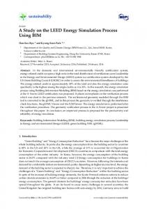
Fig. 2. Delayed ACK Processing. Burst size indicates the number of unacknowledged packets that are allowed before the sender stops sending and waits for an acknowledgment packet. In this example, the group acknowlegement packet sent by the receiver is missing packet 13 and contains two ACKs for packet 14 due to the expiration of the probe timer that resulted the sender retransmitting the last packet in the burst.
Figure 2 shows how our delayed ACK implementation works. First, assuming delayed ACK is enabled, the MAC queues packets up to the allowed burst size. For example, in this case, the burst size is five. Each packet is then transmitted one after another with a minimum interframe spacing (MIFS) between them. After transmitting the entire packet burst, the MAC waits for a group acknowledgment from the receiver. If no group acknowledgment is forthcoming, the MAC resends the last transmitted data packet to the receiver and resets the probe timer. In our implementation, the probe timer is set to twice the time it takes to transmit the last packet plus the retransmit interframe spacing (RIFS). For example, Figure 2 shows that packet 13 is lost which results in the retransmission of packet 14 after the expiration of the probe timer. It can be seen that the group acknowledgement will allow the sender to remove packets 10, 11, 12 and 14 from its queue and then send a new packet burst that contains a retransmission of packet 13 as well as new packets 15, 16, 17 and 18. In addition to the above, our implementation uses different interframe spacing (IFS) between frame transmissions depending on which ACK policy is used. For example, for the no ACK policy, each frame is separated by a minimum IFS (MIFS) whereas the immediate ACK policy separates each frame with a short IFS (SIFS), followed by an ACK transmission, and then another SIFS before the next frame is transmitted.
Packets Scheduler: Our implementation maintains three types of queues. The first queue, called the CAPqueue, is for packets to be transmitted during the CAP. Applications mark each flow with a unique stream identifier which is used by the MAC to ensure that a stream’s packets are transferred into the correct queue. Any packets from unidentified streams will be placed into the CAP-queue. The second queue, called managequeue, is for all MAC management related packets, such as association request and reply messages. Managequeue has a higher priority over the CAP-queue in that packets are transmitted from the manage-queue first. Note that although management packets have higher priority locally, these packets still need to contend for the channel with both management packets and data packets from other devices. Finally, there are the realtime queues that belong to each real-time flow. The unique stream identifier is also used by the MAC to maintain a data structure called StrmInfo that contains per-stream information such as the minimum number of allocated TUs and ordering, packet queue, and channel time request information. input : StrmInfo and StrmOrder output: Next packet to be transmitted 1 for i ← 1 to Number of Streams do 2 if StrmOrder == StrmInfo[i].Order then 3 if not StrmInfo[i].Private CTA then 4 pkt = LookupPacket(StrmInfo[i].UnACKcounter); pktttime = CalculateTxTime(pkt); 5 6 CTAstart = BeaconT ime + CAPlength + CT Aloc ; CTAend = CT Astart + CT Alength ; 7 if CTAend-CurrentTime > pktttime then 8 9 if pkt is first in CTA then 10 ScheduleTransmit(pkt, ACKPolicy, CTAstart); 11 end 12 else 13 ScheduleTransmit(pkt, ACKPolicy, MIFS); 14 end 15 end 16 else 17 StrmOrder++; 18 PickNextOrderPacket(); 19 end 20 end 21 else Beaconpkt = ConstructBeaconPacket(); 22 ScheduleTransmit(Beaconpkt , NIL, CTAstart); 23 24 StrmOrder++; 25 end 26 end 27 end
Algorithm 1: Packet scheduling algorithm implemented by the function PickNextOrderPacket. The PNC is responsible for the transmission order of each device. Once a beacon arrives, a device searches for its CTA allocation information and determines the transmission order of its flows. These flows are marked in ascending order, so a flow marked with one means that its CTA slot occurs earlier than a flow marked with two. After setting the order of its flows, a device then iteratively uses Algorithm 1, implemented by the
function PickNextOrderPacket, to pick the next packet from the desired stream. Algorithm 1 takes as input the StrmInfo data structure, which contains information on all streams, and StrmOrder, the index of the stream currently under consideration. First, the algorithm finds the stream that is specified in StrmOrder. Once found, the algorithm proceeds to determine whether the flow has sufficient time left in its CTA to transmit another data packet. In line 6-7, the algorithm determines the start and end times of the stream’s CTA which is then used to determine whether there is sufficient time left in the CTA to transmit a packet. If so, the packet is transmitted. If not, the algorithm moves onto the next stream by incrementing StrmOrder and then making a recursive call to itself. The ScheduleTransmit function accepts three parameters, one of them being the ACK policy used by a given flow. The ACK policy determines which IFS to use as well as whether it should wait for an acknowledgment packet. Further, this policy also determines when the PickNextOrderPacket function should be called again to schedule the transmission of the next packet. For example, for the no-ACK policy, it is called after waiting until the end of the previous packet plus a MIFS time. If the allocated CTA is private, denoting a time slot for a child PNC, the algorithm calls the ConstructBeaconPacket function to fill the CTABlocks data structure, containing the relevant devices’ CTA slots, which is included in beacon for advertisement to child devices. Contention Channel Access: The CAP uses a contention channel access algorithm [2] that works as follows: • Calculate a random backoff counter by drawing randomly from the interval [0, BOwin (retrycount)], where the function BOwin (retrycount) returns a window size depending on the value of retrycount by indexing into the array [7, 15, 31, 63] . • Whenever the channel is sensed idle, the backoff counter is decremented by one. Once the backoff counter is zero, the packet is transmitted. • In the event of a retransmission timeout, the retrycount is incremented by one. Then, if retrycount is no more than three, a new backoff counter is calculated with a larger window size. Otherwise, the packet is dropped. Algorithm 2 shows the pseudocode of our implementation of the IEEE 802.15.3 MAC’s contention channel access algorithm. One consideration in our implementation is that when backoffCounter is zero and there is no time left in the CAP, we delay the packet’s transmission
until the start of the next CAP at which time the packet is sent immediately.
1 2 3 4 5 6 7 8 9 10 11 12 13 14 15 16 17 18 19 20 21 22 23 24 25 26 27 28 29
input : A packet, outPkt, queued for transmission. output: Packet transmitted or setting of the backoff timer. // If we have not started backoff counter yet if backoffCounter==-1 then if MAC and Channel is idle then backoffCounter = Random(cwvalues[retrycount]); end // We call this function after BIFS time has elapsed. BackoffTimer(BIFS); end else if backoffCounter==0 then if MAC and Channel have been idled for BIFS Time then backoffCounter=-1; Trem = CheckTimeLeft in CAP(); Ttx = CalculateTxTime(outPkt); if Ttx < T rem then Transmit Packet(outPkt); end else ScheduleTx(outPkt, TNextCAP P eriod ); end end else BackoffTimer(BIFS); end end else if MAC and Channel have been idled for BIFS Time then backoffCounter–; end BackoffTimer(BIFS); end
Algorithm 2: Contention Channel Access [2]. 2) Piconet Controller: In our implementation, a device is designated as a PNC (parent or child) by setting a flag in the simulation script. If a device is designated as a child PNC, it must first associate with a parent PNC before requesting private CTAs. After being allocated a private CTA, the device then becomes a child PNC within the allocated CTA time slot. The beacon transmitted by a PNC contains key information describing each device’s CTA slot assignments in addition to the CAP and CTAP start times. To determine the type and amount of “air-time” allocated to a given flow, the PNC solicits the help of a bandwidth manager (BM) in order to perform admission control and adapt existing flows. Algorithm 3 shows the BM we have implemented. This BM uses a flow’s minimum and desired number of time units (TUs) to determine whether there are sufficient TUs in the CTAP to meet the flow’s request, including guard times1 and IFS. If there is sufficient time left in the CTAP to satisfy the flow’s desired number of TUs, the flow is admitted and the requesting device is notified.
1
Our clock’s accuracy is 10ppm
1 2 3 4 5 6 7 8 9 10 11 12 13 14 15 16 17 18 19 20 21 22 23 24 25 26 27 28 29 30
input : StrmInfo, and Flow CTA requirements for flow-i output: Time Units for flow-i while not Finish Allocating CTAs do Talloc=Total Allocated TimeUnits(StrmInfo, NumbStreams); Tmin=Min Allocated TimeUnits(StrmInfo, NumbStreams); T guard = N umberof CT As × GuardT ime; Tf ree = CT ADur − T alloc − T guard; Tf ree M in = CT ADur − T min − T guard; // Calculate requested CTAs for flow-i Treq = F lowi .DesiredT U × F lowi .CT Rq T U ; TreqMin = F lowi .M inT U × F lowi .CT Rq T U ; if Treq < Tf ree or TreqMin < Tf ree M in then if Treq < Tf ree then F lowi .AllocCT A = F lowi .DesiredT U ; end else F lowi .AllocCT A = F lowi .M inT U ; end StoreStreamInfo(F lowi ); FinishedAllocating = TRUE; end else if Tf ree M in >= TreqMin then FreeTUs Pool = Tf ree ; while F reeT U s P ool < T reqM in do strmIdx = FindStream With Max Allocation(StrmInfo); FreeTUs Pool += StrmInf ostrmIdx .AllocCTAStrmInf ostrmIdx .MinTU; StrmInf ostrmIdx .AllocCTA = StrmInf ostrmIdx .MinTU; end end end end
Algorithm 3: Bandwidth Manager. In the case when there are insufficient TUs to admit the flow, the BM will reduce the TUs allocated to existing flows. The BM does this by first checking the number of free TUs that can be made available if all flows were allocated their minimum TUs. If the resulting TUs are insufficient to meet the requesting flow’s minimum TUs, the BM rejects the incoming flow’s request. On the other hand, if there are sufficient TUs, the BM searches for the flow that has requested the highest number of additional TUs, that is, the flow with the largest difference between its allocated and minimum TUs. Once found, the BM reduces the flow’s allocated TUs to its minimum required TUs. The BM then determines whether the additional TUs are sufficient to meet the requesting flow’s minimum TUs. If not, the BM adds the freed TUs to its pool of available TUs and searches for the next flow with the highest requested TUs. This process is iterated until the BM is able to meet the requesting flow’s minimum TUs. III. S IMULATION M ETHODOLOGY This section presents our investigations into how the IEEE 802.15.3 operating parameters shown in Table II affect the performance of real-time and best-effort flows. We experimented with various values and quantitatively determined their impact on both real-time and TCP traffic. In all our simulation runs, we retained the physical layer parameters presented in [4]. Although the UWB physical layer has multi-rate capabilities, we did not use
this feature. Instead, we specified that all nodes use the highest 18Mb/s rate. Parameters Superframe length Durations of CAP Desired CTAs time units ACK policies
Studied Values 20 to 30 msec 1 to 3 msec 5 to 10 msec. no-ACK, Imm-ACK, Dly-ACK
TABLE II MAC PARAMETERS AND STUDIED VALUES IN STUDIES .
OUR SIMULATION
PNC/Sink F1 BE1 RT1
F2
RT2
BE2
TCP 1
BE3 TCP 2
BE4
Fig. 3. Simulation topology with two real-time CBR flows and two TCP flows. The acronyms RT and BE mean real-time and best-effort respectively.
Figure 3 shows the network topology used in all our studies, with the exception of the scalability study presented in Section IV-D. Nodes in our network topology remained stationary in all the simulation runs. Our network had two constant bit rate flows, F 1 and F2 that transmit packets of 564 bytes to the PNC at a rate of 6 Mb/s. At the start of each simulation, each of these flows sent a CTA request containing the variables shown in Table I to the PNC. In all our simulations, we ensured that both real-time flow requested the appropriate minimum number of TUs so that their requests were not rejected by the PNC. In addition to real-time flows, we had two competing TCP (NewReno) flows, T CP1 and T CP2 , that were started randomly. Except for the experiments in Section IV-E, packets from these TCP flows were only transmitted in the contention access period, meaning no additional CTAs were allocated for these flows in the CTA period. Further, the packet size for these TCP flows was set to 1000 bytes. Each simulation was run ten times, each for a duration of ten seconds. IV. R ESULTS A. Effect of Superframe Duration In this experiment, we varied the length of the superframe whilst keeping the length of the CAP constant at 1ms. We also investigated CTA allocations of various
sizes. Figure 4 shows the average throughput of the realtime flows when allocated CTAs with time durations of five, seven, and nine milliseconds. Further, the ACK policy used was no-ACK.
both flows are now allocated their minimum CTAs and thereby suffer further reduced throughput. 1000 1-ms 2-ms 3-ms
900 6.5
800 Average Throughput (Kb/s)
5-ms 7-ms 9-ms 6
Average Throughput (Kb/s)
5.5
5
700
600
500
400
4.5 300 4 200 3.5 100 20
22
3
2.5 20
22
24 26 Superframe Duration (msec)
28
30
Fig. 4. Average throughput of real-time flows versus superframe duration. The graph also shows the average throughput for each of the two real-time flows under varying CTA slot times.
Figure 4 shows decreasing throughput as the superframe’s duration increases; the reason being that the real-time flow must wait longer before it can send more packets in the next occurrence of its CTA. The slope of the curve shows that when a real-time flow’s throughput is limited by channel time, every one millisecond increment in superframe duration corresponds to an average reduction of 0.21 Mb/s in throughput. The size of CTAs also play a crucial role in the recorded throughput of the real-time flows. On average, increasing the CTA size from 5ms to 9ms provides an increase of 2.15 Mb/s in throughput. B. Effect of CAP Duration Figure 5 shows the effect of increasing the superframe duration on TCP throughput for several different CAP sizes. Similar to the previous case for real-time flows, the TCP traffic showed a reduction in throughput as the superframe period increased. Since the superframe time must be shared between the CAP and the CTAP, we can improve the throughput of the TCP flows by increasing the CAP duration. However, if this is done, less time will be available to the real-time flows in the CTAP. For example, Table III shows the reduction in throughput for the real-time flows when the CAP durations is increased. The reason for the reduction is that when the CAP is 2ms, there is sufficient time in the CTAP for only one real-time flow to receive its full desired CTA allocation – the other real-time flows is reduced to its minimum CTAs. Further increasing the CAP to 3ms means that
24 26 Superframe Duration (msec)
28
30
Fig. 5. Average TCP throughput versus superframe duration for different CAP durations.
CAP Duration 1ms 2ms 3ms
Change in RT Throughput (Mb/s) 0.00 0.92 1.61
TABLE III R EDUCTION IN REAL - TIME FLOWS ’ THROUGHPUT DUE TO INCREASES IN CAP DURATION .
C. ACK Policies The IEEE 802.15.3 MAC has three ACK policies, with the delayed ACK policy used only in the CTA period. Therefore, we present results showing the impact of the different ACK policies on two real-time flows. For the delayed ACK policy, we experimented with burst sizes from 10ms to 30ms. In all cases, the CTA TUs of both flows was 9ms, with a superframe duration of 20ms. Further, given the close proximity of the sender and receiver devices, we did not record any errors or dropped packets. Table IV shows the average throughput as well as the percentage of traffic that was due to the acknowledgment messages for each ACK policy. Without exception, the overheads due to the acknowledgment messages were marginal. This means that efforts to reducing the quantity of acknowledgment messages can gain only a slight increase in throughput. D. Contention Channel Access’s Impact on TCP Fairness and Throughput In this experiment, we investigated whether the IEEE 802.15.3 channel access algorithm is fair, especially as
Average Throughput (Mb/s) 13.10 12.64 12.86 13.03 13.10
Percentage of Total Traffic 0.00 0.92 0.59 0.47 0.43
TABLE IV I MPACT OF ACK POLICIES ON THROUGHPUT AND THE
0.95 Packet Size=1000 Packet Size=500 Packet Size=100 0.9
0.85
0.8 Fairness Index
ACK Policy NO-ACK Imm-ACK Dly-ACK-10 Dly-ACK-20 Dly-ACK-30
0.75
0.7
0.65
PERCENTAGE OF ACKNOWLEDGMENT TRAFFIC VERSUS DATA 0.6
TRAFFIC .
0.55 2
E. TCP Flows in the CTAP This section presents the results of our experiments on running TCP in the CTAP instead of the CAP. In order
6
8 10 Number of TCP Sessions
12
14
Fig. 6. Fairness index versus increasing TCP sessions (CAP set to 1ms). Packet size is in bytes. 300 PacketSize=1000 PacketSize=500 PacketSize=100 250
Avg. Throughput (Kb/s)
the number of TCP sessions increases. For this study, the CAP was fixed at 1ms and the number of TCP sessions was varied from two to fifteen. Moreover, we investigated TCP packets with sizes of 1000, 500, and 100 bytes and increased the number of simulation runs to 50. To measure fairness we used Jain et al. [5]’s fairness index. Figure 6 shows the fairness index versus the number of concurrent TCP sessions. It can be seen that the fairness index is low when there are a small number of connections, and fairness improves with increasing flows but starts declining again when there are a high number of flows. Interestingly, TCP flows using packet size of 100 bytes have better fairness with increasing number of flows Figure 7 shows the corresponding average throughput when we increased the number of competing TCP connections. We can see that as the number of TCP flows increase, the average throughput drop drmatically and fairness starts to decline. Despite having better fairness TCP flows with 100 bytes packet size have very low throughput. The poor fairness property and wide disparaties in throughput experienced by a given flow is due to the contention channel access method not employing RTS/CTS exchange in order to combat the hidden terminal problem. We found that some flows experienced high number of errors which led to these flows having lower throughput, and enabling other flows to dominate the channel by taking over these flows’ “air-times”. At smaller packet size, flows have a better chance of gaining access to the channel due to higher collisions among flows, hence giving access opportunities to other flows that are awaiting to transmit a packet albeit at a lower throughput.
4
200
150
100
50 2
4
6
8 10 Number of TCP Sessions
12
14
Fig. 7. Average throughput versus increasing number of TCP sessions (CAP set to 1ms). Also shown is the 95% confidence interval for the sample mean. Packet size is in bytes.
to support a single TCP flows, two reservations need to be made because the IEEE 802.15.3 MAC allows for only unidirectional data transmissions in a single CTA slot. Therefore, both the sender and receiver are required to request CTA slots from the PNC so that there are transmission slots available for both data and acknowledgement packets (subsequently referred to as down and up channels respectively). In this experiments, the TCP packet size was set to 1000 bytes. Our first investigation was on the impact of different CTA sizes on the down and up channels. Firstly, we defined a TU block, T blk = 10msec, that was used to partition the CTAP into discrete blocks. We then experimented with different CTA allocation ratios between the up and down channels, T blk , by increasing the TDownChannel from 1ms to 9ms in Equ. 1, where the denominator corresponds to the up channel’s CTA size. TDownChannel CT AAllocationRatio = (1) Tblk − TDownChannel Figure 8 shows the effect of different CTA allocation
9000 SuperFrame Duration=10ms SuperFrame Duration=20ms 8000
7000
Throughput (Kb/s)
6000
5000
4000
3000
2000
1000
0 0
Fig. 8.
1
2
3 4 5 6 CTA Allocation Ratio (sender/receiver)
7
8
send more data. 2600 Aggregate 2400 2200 2000
Throughput (Kb/s)
ratios on the throughput of a single TCP flow under two different superframe durations. For a superframe duration of 10ms, the TCP flow’s throughput is initially very low as almost all the CTAP is allocated to the up channel and the down channel has very little time to send data packets. As the down channel CTA increases, the TCP flow’s throughput increases and reaches a peak of 8076 Kb/s when the sender and receiver CTA sizes are at 6ms and 4ms respectively. As the down channel allocation is increased further, the limited up channel time becomes a bottleneck and quickly results in a severe reduction in throughput. In a different experiment, we set the superframe duration to 20ms. Figure 8 shows that a reduction in throughput occurred, compared to the case when a superframe of 10ms duration was used. This is because in addition to the size of the CTA slot mentioned before, the increased in superframe length translates to longer RTT; approximately equal to the length of the superframe. This means a flow requires more round trips before it is able to take advantage of its allocated CTA size. This coupled with the effect of CTA size lead to a reduction in throughput.
1800 1600 1400 1200 1000 800 600 400 1
2
3
4
5 6 CAP Sizes (msec)
7
8
9
10
Fig. 9. Aggregated throughput of ten flows with fixed down channel at 1msec, and all acknowledgement messages are sent in the CAP of varying size
V. C ONCLUSION
AND
F UTURE W ORK
We have presented our implementation of the IEEE 802.15.3 MAC in the widely used ns-2 simulator, and also our implementation of a simple packet scheduler and bandwidth manager. From our studies we find that the IEEE 802.15.3 CAP channel access mechanism to be unfair due to the hidden terminal problem. Apart from that, when running TCP in the CTAP we find that data and acknowledgment slot sizes and superframe duration affect how fast a TCP flow grows its congestion window. Currently, we are carrying out more experiments and studying in greater detail the impact of fairness as well as the choice of bandwidth managers and scheduling algorithms. Further, we are implementing and studying other features of the MAC, including PNC handover, channel probing and switching, coexistence, and power saving modes.
9
Throughput versus CTA allocation ratio.
Lastly, we experimented with the idea of having TCP flows transmit their acknowledgement packets in the CAP. The advantage of this approach is that we save on having to reserve a discrete acknowledgement channel for each flow. In these experiments, we only allocated 1ms CTA for the down channel time for each of ten TCP flows. Figure 9 shows the impact of varying the CAP duration on TCP throughput. Initially, as the CAP time is increased, the throughput of all flows improves. However, after a CAP time of 7ms, the throughput begins to decrease since the time being allocated to the CAP for acknowledgements could be better used in the CTAP to
R EFERENCES [1] IEEE, “802.15 WPAN task group 3 (TG3).” http://www.ieee802.org/15/pub/TG3.html. [2] IEEE 802.15.3 Working Group, “Part 15.3: Wireless medium access control (MAC) and physical layer (PHY) specifications for high rate wireless perosnal area networks (WPAN).” IEEE Draft Standard, Draft P802.15.3/D16, Feb. 2003. [3] S. McCanne and S. Floyd., “ns network simulator-2.” http://www.isi.edu/nsname/ns/. [4] J. Widmer, “EPFL ns-2 UWB implementation.” Ns-2 simulation source code. http://icapeople.epfl.ch/widmer/uwb/index.html. [5] R. Jain, D.-M. Chiu, and H. Hawe, “A Quantitative Measure of Fairness and Discrimination for Resource Allocation in Shared Computer Systems.” DEC RR TR-301.