A single mediaprocessor-based programmable ... - Semantic Scholar
Recommend Documents
The goal of programmable networking is to simplify the deployment of network ..... The Tempest project at the University of Cambridge [34] has investigated the ...
this paper introduces a small language that lets the programmer describe .... We define a simple EDSL to specify type co
Jun 2, 2005 - Follow this and additional works at: http://repository.cmu.edu/ .... cube of distance, whereas the flux due ... 100 ms for a step-reconfiguration.
We propose a specification-based approach that allows analyst to specify and control ... references, data slice, program slice, program chops, etc. System level ...
and M.S. degrees in electrical engineering from the. Federal University of ParaÃba (UFPB), Campina. Grande, Brazil, in 1993 and 1996, respectively, and.
and are also with the Japan Science and Technology Agency (JST), Kawaguchi- shi, Saitama ..... gree in information engineering and M.S. degree in information ...
[2] Jeffrey Mackie-Mason and Hal Varian, âPricing the Internet â JFK School for Government. 1993. [3] Scott Shenker âService Models and Pricing Policies for an ...
tiuser detection and Viterbi decoding on this simulator. We present ..... ios. Our current research aim is to solve the bottlenecks posed by the algorithms to design ...
Network, http://koren2.kr/koren/eng/. [6] G. Adam Covington, Glen Gibb, John Lockwood, and Nick McKeown,. âA Packet Generator on the NetFPGA Platformâ, ...
The weights are stored on polysilicon floating gates, providing long-term retention with ..... by the Sloan Research Fellowship, by a grant from the IBM Almaden ... in Advances in Neural Information Processing Systems 7, MIT Press, Cambridge,.
ESANN 2010 proceedings, European Symposium on Artificial Neural Networks - Computational Intelligence and Machine Learning. Bruges (Belgium), 28-30 ...
such as Lotus 1-2-3 and Microsoft Excel also offer macro languages for ... Similarly, Lotus is planning a cross-application scripting language for their product.
1515 Holcombe Boulevard, Box OR9 Houston, Texas 77030 USA. K. Ratanachoo, K. ... October 5-9, 2003, Squaw Valley, Callfornla USA. O-974361 I-0.
held by: WTEC, Loyola College (Maryland). 14. CompanËó, R. Technological Roadmap for European Nanoelectronics at kftp://ftp.cordis.lu/pub/ist/docs/.
One timing setting is not ideal as engine rpm and loads change. By adjusting ...
Start Timing: The amount of timing advance that is in place when the engine is
idling or during start up. ... Two Tabs: For use on engines such as the CRF450R
with a
Two Tabs: For use on engines such as the CRF450R with a dual tab flywheel
and trigger design. REV LIMITS. There are two rev limits to program with the PN ...
Nov 22, 2012 - for dynamic service provisioning in Future Internet scenar- ios. It is equipped with ... characterization of the optical devices and physical layer aspects is .... The idea is to add an adequate level of flexibility to high- capacity .
capable of choosing the service-specific balance between application-layer .... interference, and to avoid possible collusion against the hosting network node ...
Information Society â including business, health care, education, science, and government â it is ..... detection and repair. By focusing on a particular ... Against DDoS Attacks, AT&T Technical Report (December 2001). 9. Chen, X., Heidemann ...
Andres W. Martinez, Scott T. Phillips, Zhihong Nie, Chao-Min Cheng, Emanuel Carrilho,. Benjamin J. Wiley and George M. Whitesides. This paper describes ...
Key words: Electronic Government, Asynchronous Messaging, Messag- ing Middleware .... services, and periodicals - publications, legislations and newsletters. 3. ...... Schema [24] and the transformation extension applies XSLT [25] templates.
The movement to allow programming of parts of the graphics pipeline led to GPU vendors providing custom APIs for using their GPUs for more general purpose ...
is typically a device, like a PDA, a laptop, a PC, or smaller devices, .... keystrokes keyboard (or touchscreen), a tiny screen (⤠4 inch), an IP or ad ..... Page 17 ...
message-passing communications model for topology management in wireless ... Applications and Services in Wireless Networks, Boston, Massachusetts,. USA, August 2004. ..... [6] Bluetooth Special Interest Group Specification, Version 1.2,.
A single mediaprocessor-based programmable ... - Semantic Scholar
formance programmable computing engine with high data transfer bandwidth and .... processing stages could be reordered, if needed, to optimize the image quality. ..... In addition, we limited the coordinate search space based on the sector geometry ..... ultrasound imaging a more affordable and attractive diagnostic tool.
64
IEEE TRANSACTIONS ON INFORMATION TECHNOLOGY IN BIOMEDICINE, VOL. 7, NO. 1, MARCH 2003
Correspondence________________________________________________________________________ A Single Mediaprocessor-Based Programmable Ultrasound System Siddhartha Sikdar, Ravi Managuli, Lixin Gong, Vijay Shamdasani, Tsuyoshi Mitake, Tetsuya Hayashi, and Yongmin Kim
Abstract—We have developed a programmable ultrasound imaging system using a single commercially available mediaprocessor. We have efficiently mapped all of the necessary B-mode processing algorithms on the underlying processor architecture, including envelope detection, dynamic range compression, lateral and axial filtering, persistence processing, and scan conversion. Our system can handle varying specifications ranging from 128 vectors and 512 samples per vector to more than 256 vectors and 1024 samples per vector. For an image size of 330 vectors and 512 samples per vector, it can process 30 frames per second using a 300-MHz MAP-CA mediaprocessor from Hitachi/Equator Technologies. This programmable ultrasound machine will not only offer significant advantages in terms of low cost, portability, scalability, and reduced development time, but also provide a flexible platform for developing and deploying new clinical applications to aid the clinicians and improve the quality of healthcare to patients. Index Terms—Direct memory access (DMA) programming, instruction and data-level parallelism, mediaprocessor, programmable ultrasound machine, ultrasound B-mode system.
I. INTRODUCTION Ultrasound has become a prevalent medical imaging modality because it is safe, noninvasive, easy to use, less expensive, and more portable than other modalities such as computed tomography (CT), magnetic resonance imaging (MRI) and positron emission tomography (PET). Traditionally, ultrasound machines have been built using multiple fixed-function circuit boards to meet the high computational and data rate requirements, thus they were not very flexible in deploying new features and applications and were more expensive to develop and upgrade. In 1996, we developed the programmable ultrasound image processor (PUIP), which provided a programmable subsystem inside the ultrasound machine [1]. The PUIP was integrated into the Siemens’ ultrasound machines and has clearly demonstrated the clinical benefits of the programmable approach through rapid prototyping and deployment of new applications running on the same hardware, e.g., panoramic imaging, three-dimensional (3-D) ultrasound and harmonic imaging [1]. Although the PUIP increased the flexibility of the ultrasound machine, most of the ultrasound processing needed in B and color modes were performed by special purpose hardwired circuit boards, thus it
Manuscript received January 9, 2002. S. Sikdar and L. Gong are with the Electrical Engineering Department, University of Washington, Seattle, WA 98195 USA (e-mail: [email protected]; [email protected]). R. Managuli and V. Shamdasani are with the Department of Bioengineering, University of Washington, Seattle, WA 98195 USA (e-mail: [email protected]; [email protected]). T. Mitake and T. Hayashi are with Hitachi Medical Corporation, Kashiwa-shi, Chiba-Ken 277-0804, Japan (e-mail: [email protected]; [email protected]). Y. Kim is with the Departments of Bioengineering and Electrical Engineering, University of Washington, Seattle, WA 98195 USA (e-mail: [email protected]). Digital Object Identifier 10.1109/TITB.2003.808512
was still difficult to deploy new features and improved algorithms that require changes in the underlying hardware. Ultrasound machines designed over the past few years have introduced some flexibility in core ultrasound processing through the use of digital signal processors (DSPs) and reconfigurable hardware, such as field programmable gate arrays (FPGAs) [2]. In recent years, some PC-based low-end systems have been developed and introduced commercially [3]–[7]. While the PC enables efficient management of patient data, facilitates interconnectivity with emerging digital archiving and retrieval systems, and also can be used for some image processing, application-specific integrated circuits (ASICs)/FPGAs are still utilized for performing much of the ultrasound processing. One obstacle in performing the core ultrasound processing in software has been the lack of a high-performance programmable computing engine with high data transfer bandwidth and integrated standard I/O interfaces. Efficient mappings of ultrasound algorithms to the underlying processor architectures have been lacking as well. Our goal is to develop a software-based ultrasound system without sacrificing the diagnostic capability and performance of an ultrasound machine. To achieve our goal, we aim to use a new generation of high performance processors, known as mediaprocessors, as the main computing engine. Mediaprocessors, like the Hitachi/Equator Technologies MAP-CA, the Texas Instruments Incorporated TMS320C64, and the TTI TriMedia, have been recently introduced, primarily targeting multimedia and consumer electronics applications. These programmable processors can attain a high computational throughput at low cost by utilizing fine-grained parallelism at the instruction and data level. In addition, they are well suited to processing streaming ultrasound data since their architectures and instruction sets are designed for processing streaming multimedia data. Many key compute-intensive algorithms in ultrasound image processing [e.g., convolution and fast Fourier transform (FFT)] have comparable, if not better, performance on modern mediaprocessors to that of hardwired approaches [8], [9]. In this paper, we will describe a flexible and cost-effective ultrasound system based on a single mediaprocessor. The B-mode image quality and frame rates of our system match those of existing commercial ultrasound machines. We will describe how B-mode processing algorithms have been tailored for good performance on a mediaprocessor. Also, we will analyze our results and discuss future programmable ultrasound machines. II. B-MODE PROCESSING Typical B-mode processing stages in a modern ultrasound machine are illustrated in Fig. 1. B-mode imaging involves data acquisition, echo processing and display. In the acquisition stage, the acoustic echoes received from the tissue are converted to electrical signals by the transducer and these signals are digitized by analog-to-digital converters. The beamformer can perform dynamic focusing, apodization and steering of both transmitted and received ultrasonic waveforms [10]. The time-gain-compensation (TGC) circuits amplify signals with a variable gain that is proportional to depth. The radio frequency (RF) demodulator digitally removes the high-frequency carrier by quadrature demodulation and decimation, resulting in in-phase (I ) and quadrature (Q) samples represented as a complex quantity I (t) + jQ(t). After demodulation and decimation, the signal of interest for producing the tissue images is the envelope of I (t) + jQ(t).
IEEE TRANSACTIONS ON INFORMATION TECHNOLOGY IN BIOMEDICINE, VOL. 7, NO. 1, MARCH 2003
65
quality. We have chosen the order of processing stages as shown in Fig. 1, which is typical in commercial systems. III. ARCHITECTURE OF THE MAP-CA MEDIAPROCESSOR
Fig. 1.
B-mode processing stages.
The echo processor computes the magnitude of the echo vector, Ba (t) = I 2 (t) + Q2 (t). A collection of vector envelopes is called a frame. At this point, the echo signal has a large dynamic range, e.g., 80 dB or higher. Display monitors as well as human visual systems typically have a dynamic range of about 30–40 dB, thus the dynamic range of the echo signal could be compressed. This is typically performed by logarithmic compression. The resulting vector, Bb (t) = log[Ba (t)], is further filtered to enhance edges and/or clean up noise. Filtering is applied along each vector (axially) and across vectors (laterally) to improve the signal to noise ratio [11]. To preserve the smoothness of the image while enhancing the edges, we have used difference of Gaussian (DOG) kernels [12]. At this stage, we apply temporal filtering on multiple frames for further noise reduction and speckle suppression [13], [14]. Temporal filtering [14] is more attractive compared to spatial filtering [15] for speckle suppression because of the reduced computational requirement. To remove streaking artifacts produced by temporal averaging of fast moving objects [16], the temporal filtering can be made data-dependent. This adaptive temporal filtering is called persistence processing. The amount of temporal filtering is made inversely proportional to the difference between the new and previous samples through the following equation:
Bout (i) = Bin (i) + 1 Bout (i 0 1) 1+
(1)
where i is the frame number and = f (255 0 jBin (i) 0 Bout (i 0 1)j) is a parameter controlling the level of persistence and
depends upon the previous output and current input. Before displaying the processed frame on a raster monitor, scan conversion needs to be performed to convert the acquired ultrasound data from polar coordinates to the Cartesian coordinates of the raster display [17]. The user interface of most ultrasound machines allows the display parameters, e.g., zoom, pan, rotation, and sector angle, to be changed. This geometry information is also incorporated into this transformation. The scan converter performs address transformations and interpolations between neighboring pixel values to smoothen the effects of coordinate resampling [18], [19]. Prior to displaying the scan-converted frame, gamma correction is performed to account for variable sensitivities of the display monitor and the human visual system to different brightness levels. Even though the B-mode processing is similar in many ultrasound machines, the order of the processing stages can be different from one system to the next. Dynamic range compression could, for instance, be performed after filtering. Also, some image enhancement operations, e.g., filtering and persistence processing, could be performed after scan conversion. Since our system is programmable, some of these processing stages could be reordered, if needed, to optimize the image
The architecture of the MAP-CA is optimized for image and video processing [20]. The very long instruction word (VLIW) processing core consists of two clusters, a 32-kB four-way set-associative data cache, and a 32-kB two-way set-associative instruction cache. Each cluster has an integer arithmetic logic unit (IALU), and an integer graphics arithmetic logic unit (IGALU). The IALU can perform either 32-bit fixed-point arithmetic operations or 64-bit load/store operations while the IGALU can perform 64-bit partitioned arithmetic operations. Many IGALU instructions can specify different data partitions (each with eight, 16, or 32 bits), providing a performance improvement by a factor of approximately eight, four, or two via data-level parallelism, respectively. The two clusters are capable of executing four different instructions (e.g., two on IALUs and two on IGALUs) per clock cycle. The IGALU supports powerful instructions. For example, a single inner-product instruction can perform eight 16-bit multiplications in parallel using specialized 128-bit registers, summing the results into a 32-bit output [8]. Such powerful instructions can provide high performance for filtering operations used extensively in ultrasound and other medical imaging applications. The MAP-CA includes many similar instructions with various multimedia-optimized extensions, e.g., rounding, saturation, and shifting modes. B-mode ultrasound processing involves several fixed-point iterative algorithms, where flexible rounding modes are useful for reducing error propagation. In addition to the powerful processing core and instruction set, the MAP-CA has several high-bandwidth I/O interfaces such as peripheral component interconnect (PCI) and transport channel interface (TCI), which can be used efficiently for acquiring and displaying data. The MAP-CA also has an advanced direct memory access (DMA) controller, which supports various data transfer modes. The DMA engine can be used to move data between on-chip (data cache) and off-chip memory, between different off-chip memory locations, and also between I/O interfaces and memory, independent of the computing units. The built-in multiple I/O interfaces in addition to the DMA engine distinguish the MAP-CA from other processors and facilitate the development of a highly-integrated compact system. The processor currently runs at 300 MHz, and the external memory is 133-MHz synchronous dynamic random access memory (SDRAM). The 32-bit PCI bus runs at 33 MHz, and two TCI buses run at 27 MHz each. IV. B-MODE SYSTEM According to our analysis of the ultrasound computational requirements, envelope detection, axial and lateral filtering and persistence processing require about 250 operations per sample [21]. Dynamic range compression is typically implemented using a lookup table (LUT). Using the DMA controller on the MAP-CA mediaprocessor, LUT operations can be performed efficiently while the computing units are performing other tasks. If the transducer acquires V vectors with S samples per vector and the desired frame rate is F frames per second (fps), then 250 2V 2 S 2 F operations per second are required for echo processing. Bilinear interpolation for scan conversion using the four nearest neighbor pixels requires 20 operations per output pixel. Assuming an output display size of M 2 N , the scan conversion interpolation requires 20 2M 2 N 2 F operations per second. The address transformation for scan conversion is typically recomputed only when the user changes the display parameters, e.g., zoom, pan, rotation, and sector angle. This requires 160 operations to compute each polar-to-Cartesian transformation in 16 bits using the CORDIC algorithm [22] and additional 14 operations for performing the affine
66
IEEE TRANSACTIONS ON INFORMATION TECHNOLOGY IN BIOMEDICINE, VOL. 7, NO. 1, MARCH 2003
Fig. 2. Block diagram of our mediaprocessor-based ultrasound system.
transformation. Gamma correction is implemented using a LUT. Thus, the total computational requirement of the echo processing and scan conversion is 250 2 V 2 S 2 F + 20 2 M 2 N 2 F operations per second, while it takes additional 174 2M 2 N operations whenever any display parameter is changed. Low-end ultrasound machines typically support up to 128 vectors with 512 samples per vector and a maximum frame rate of around 30 fps, whereas high-end systems support 256 or 512 vectors with up to 1024 samples per vector and have high frame rates exceeding 30 fps. Frame rates of up to 70 fps are typically supported on high-end systems for applications like cardiac imaging, but with a reduced image size. The output display resolution on standard ultrasound monitors is typically 640 2 480, although some high-end systems can have the display resolution of 800 2 600. Using these numbers for V , S , M , N , and F , the computational requirements of echo processing and scan conversion can range from 0.7 billion operations per second (BOPS) for a low-end system to seven BOPS for a high-end system. Modern high-end ultrasound systems typically use 128 channels for beamforming. Thus, the data rate can be very high, e.g., 10 Gb/s when each channel is sampled at 40 MHz and 12 bits. The I/O interfaces of modern programmable processors are not capable of sustaining this data rate unless a large number of processors are used in the system. Therefore, we presently use the front-end subsystem of a commercial ultrasound machine (Hitachi Medical Corp.’s EUB 6000) to perform beamforming and time-gain-compensation. The data rate is reduced further after RF demodulation and decimation, e.g., 40 MB/s for 1024 samples/vector with the pulse repetition frequency (PRF) of 10 kHz, which can be readily handled by a single MAP-CA. An FPGA is used to perform RF demodulation and decimation. The demodulated I and Q data are then sent to the programmable back-end subsystem. A block diagram of our mediaprocessor-based ultrasound system is shown in Fig. 2. The back-end processing is implemented on a single mediaprocessor, which interfaces to the FPGA board via the MAP-CA’s TCI. The demodulated data received on the TCI interface are parsed, formatted, and stored in memory. The B-mode tasks of echo processing, scan conversion, and gamma correction are then performed. The processed data from the MAP-CA are transferred to the host processor via the PCI bus for display. The host exchanges the control information with the MAP-CA, FPGA and beamformer boards via a shared memory interface, including parameter updates from the user interface and image enhancement. Although advanced mediaprocessors like the MAP-CA are theoretically capable of sustaining the computational throughput of ultrasound processing, high performance is not guaranteed unless the algorithms are carefully mapped to exploit parallelism at both data and instruction levels and maximally utilize the advanced instructions and multiple computing units. We have been able to obtain good performance by carefully designing and mapping our B-mode processing algorithms to the underlying architecture and also by using programming techniques such as loop unrolling, software pipelining, and avoiding conditional branching [8]. We have developed a set of criteria for analyzing the
theoretical and actual algorithm performance on mediaprocessors [23]. For our system, C with intrinsics (hints to the compiler about the assembly instructions to use for particular operations) was sufficient to obtain efficient resource utilization for the majority of processing tasks according to these criteria. With sophisticated processing core architecture, the overall performance of a particular processing task is often limited by the throughput in moving the data between on-chip and off-chip memory. The DMA engine on the MAP-CA can transfer the data between different memory and I/O locations, concurrently with the computing units by overlapping the memory access activities with the computation activities. Some examples of how we have mapped the B-mode processing algorithms efficiently to the MAP-CA architecture and utilized the DMA engine for obtaining better performance are discussed next. V. B-MODE ALGORITHM MAPPING ON MAP-CA A. Envelope Detection and Dynamic Range Compression On a fixed-point processor like the MAP-CA, the computation of 2 2 = I (m; n) + Q (m; n) for envelope detection (where m and n are the vector number and sample number, respectively) can be implemented either by using successive approximation like the CORDIC algorithm [22] or a LUT approach. The CORDIC algorithm is computationally expensive requiring 160 operations for 16-bit I and 2 2 Q. An alternative approach is to compute I (m; n) + Q (m; n) and use an iterative square-root algorithm to compute Ba (m; n). Using the square-root algorithm proposed by Prado and Alcantara [24], 83 operations are required for 16 iterations. The LUT approach is the least computationally expensive, but it requires an enormous amount of memory. For example, an LUT with 32-bit indexes (16 bits each for I and Q) and 16-bit entries would require 8 GB of memory, which is currently impractical. We implemented the computation of Ba (m; n) = 2 2 I (m; n) + Q (m; n) by combining the successive approximation and LUT techniques, thus striking a balance between the computational complexity and the memory usage. A square-root LUT with a 12-bit index is used to determine the most significant 6 bits. The lower 10 bits of the 16-bit square-root output are then obtained using ten iterations of the Prado and Alcantara’s algorithm [24]. The size of the LUT required is only 4 kB (212 ), which can easily fit in the MAP-CA’s 32-kB data cache. The dynamic range compression using a logarithmic LUT requires 16-bit indexes and 8-bit entries, which corresponds to a 64-kB LUT. Thus, on the MAP-CA processor, it is not possible to keep all of this LUT on-chip. The indices to the logarithmic LUT, Ba (m; n), are nonsequential. Therefore, unless the entire LUT is present in the cache, there will be multiple cache misses. Simulation results obtained using a cycle accurate MAP-CA simulator show that cache misses cause the processor to stall more than 20% of the time, waiting for data from off-chip memory. Thus, we used the guided transfer mode of the DMA engine [25], where the indexes Ba (m; n) are used as address offsets within the logarithmic LUT in off-chip memory and the corresponding entries log(Ba (m; n)) are moved into the off-chip output frame memory. Ba (m; n)
B. Processing Echo Signals for Enhanced Image Quality The image quality can be enhanced through axial and lateral filtering as well as persistence processing. The filter sizes can be variable. Typically, for abdominal applications, a 3-tap low-pass filter is used in the lateral direction while a 16-tap edge-enhancement filter is used in the axial direction [11]. The specialized inner-product-add instruction described in Section III is used to perform filtering. We have previously reported mapping of a convolution algorithm on the MAP-CA, which
IEEE TRANSACTIONS ON INFORMATION TECHNOLOGY IN BIOMEDICINE, VOL. 7, NO. 1, MARCH 2003
has performance comparable to many hardwired implementations [8]. Our axial and lateral filtering is based on this implementation. Persistence processing using (1) requires division operations, which needs to be avoided in fixed-point processors like the MAP-CA. By rearranging the terms in (1), Bout (i) can be expressed as
Bout (i) = sign(Bin (i) 0 Bout (i 0 1)) 1 + Bout (i 0 1)
67
TABLE I EXECUTION TIME IN MILLION CYCLES OF EACH B-MODE PROCESSING TASK (330 512 INPUT, 600 420 RGB OUTPUT)
2
2
(2)
where = jBin (i) 0 Bout (i 0 1)j=1 + = f 0 (jBin (i) 0 Bout (i 0 1)j). Equation (2) can result in faster computation compared to (1) because can be obtained from a simple 256-byte LUT indexed by jBin (i) 0 Bout (i 0 1)j. The MAP-CA has instructions for performing partitioned absolute differences, which enables computation of jBin (i) 0 Bout(i 0 1)j for eight pixels in parallel. To avoid conditional branching, both + Bout (i 0 1) and 0 + Bout (i 0 1) are computed and one of these is assigned to Bout (i) depending upon the sign of (Bin (i) 0 Bout (i 0 1)). C. Scan Conversion Scan conversion involves address generation and data interpolation. For fast address generation, we implemented the CORDIC algorithm in computing the square root and arctangent in fixed-point arithmetic. In addition, we limited the coordinate search space based on the sector geometry, thereby reducing the number of operations. The interpolation step requires nonconsecutive input pixels to be loaded from input memory [19]. Due to the lack of spatial locality, nonsequential memory accesses result in a significant number of datacache and SDRAM row misses. This leads to large memory access latency, negatively impacting the performance. If we rely on cache only, nearly 80% of the total cycles are spent in memory accesses. Utilizing double-buffering with the DMA engine [25], the memory access latency can be overlapped with the computation required by interpolation. The guided transfer uses the LUT of input addresses to prefetch the nonsequential input pixels and interpolation coefficients to on-chip memory before they are needed in inner-product. With this approach, we can compute 2 2 2 bilinear interpolation with a single cycle throughput on the MAP-CA. Our implementation of scan conversion is described in greater detail elsewhere [19]. VI. RESULTS AND DISCUSSION A. Methodology We have tightly integrated our mediaprocessor-based back-end board and FPGA-based board with the front end of the EUB 6000 scanner. Parameters, e.g., the number of vectors and depth of tissue being imaged, can be changed interactively using the EUB 6000’s user interface. The front-end subsystem acquires the ultrasound echoes, and the FPGA board generates the raw I and Q data, which are then processed by the mediaprocessor board and displayed in real time. The number of clock cycles taken by each B-mode processing task has been measured under different scenarios. Table I lists the number of cycles for each individual B-mode processing task on a single MAP-CA for a 330 2 512 16-bit input image and a 600 2 420 RGB output display. To process all of the B-mode processing tasks individually, it takes 15.21 Mcycles (50.7 ms @300 MHz). B. System-Level Optimization As shown in Table I, all of the individual processing tasks are heavily I/O-bound, i.e., the number of clock cycles required to move the data between on-chip and off-chip memory (ti=o ) is more than the computation cycles (tcompute ). If each algorithm is implemented individually, requiring the data to be moved between on-chip and off-chip for each algorithm, then the total estimated cycles to process one B frame is
j j j max(tcompute ; ti=o ) (where j denotes the j th algorithm). However, multiple tasks that are performed sequentially can often reuse the data brought on-chip for processing before the results are stored back to memory. In such cases, the total cycles can be reduced to
ttotal =
ttotal =
max(( i j 2S
j i tcompute ); ti=o
) +
j2 = [S
j j max(tcompute ; ti=o )
where Si is the ith set of tasks that can process the data sequentially i once they are brought on-chip and ti=o is the number of cycles required to bring the data on-chip and move the final result to off-chip memory for Si . Individual processing tasks, like axial/lateral filtering and persistence processing, have a significantly higher ti=o compared to tcompute . On the other hand, these tasks can be executed sequentially once the data have been brought on-chip. Combining these tasks with a single data flow will reduce ttotal . Similarly, envelope detection and dynamic range compression can be combined with another data flow. However, scan conversion cannot reuse the data brought on-chip because it needs to access the data in a nonsequential manner. Thus, it does not belong to any Si . Using such techniques, we have been able to significantly reduce the overall execution time for performing B-mode processing. Envelope detection combined with dynamic compression takes 2.54 Mcycles while axial/lateral filtering combined with persistence processing take 1.99 Mcycles. With these system level optimizations, ttotal is reduced by about 41.4% from 15.21 Mcycles (50.7 ms) in Table I to 8.91 Mcycles (29.7 ms). Additional 10% processor cycles are used for synchronization and data formatting after receiving packets from the FPGA board. Therefore, a single 300-MHz MAP-CA mediaprocessor can process 30 fps for 330 vectors, 512 samples per vector, and a 600 2 420 output display. C. Performance Analysis for Different System Parameters The overall frame rate of an ultrasound system is controlled by the smaller of the processing frame rate (fproc ) and the acquisition frame rate (facq ). If fproc is smaller than facq , some frames may need to be dropped. If fproc is larger than facq , some additional frames can be inserted by interpolation to increase a display frame rate. In most hardwired systems, the overall frame rate is limited by facq . For a softwarebased system, fproc could limit the performance. As was discussed in Section IV, the B-mode computational requirement (thus fproc ) is determined by the number of vectors (nvectors ), the number of samples per vector (nsamples ), and the output display resolution. In contrast,
68
IEEE TRANSACTIONS ON INFORMATION TECHNOLOGY IN BIOMEDICINE, VOL. 7, NO. 1, MARCH 2003
(a)
(b)
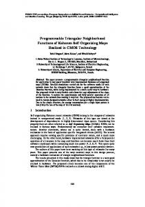
Fig. 3. Relationship of f and f versus number of vectors and depth (a) when depth is fixed at 24 cm and (b) when the number of vectors is fixed at 256.
facq depends upon the tissue depth to be imaged (depth), nvectors and
the number of vectors produced by the beamformer per transmission (nbeams ) according to the following equation: facq =
c
2 nbeams
2 2 depth 2 nvectors
(3)
where c is the velocity of sound in tissue, typically 1540 m/s. nvectors and nsamples depend upon the probe and clinical application. Abdominal applications using a 3.5-MHz sector probe typically image depths up to 25 cm and require a large field of view with nvectors greater than 256. Frame rates of 20 fps are often sufficient to capture tissue motion. Cardiac applications, on the other hand, require a higher frame rate of around 60–70 fps, while a phased-array probe typically used is smaller in size and number of vectors (nvectors ) due to the limited viewing window. A linear 7.5-MHz probe can penetrate a shallow depth but is useful for high-resolution vascular imaging. In an ultrasound system, nsamples is determined by the RF demodulator and is a function of the sampling frequency, the center frequency and the bandwidth of the ultrasound signal. Often, it cannot be changed dynamically and is constant for a particular probe and/or system. High-end and mid-range systems can have dual-beam acquisition (nbeams = 2) in order to increase facq . Fig. 3(a) shows facq and fproc of our B-mode system as a function of the number of vectors. The maximum depth of tissue being imaged is 24 cm using a 3.5-MHz transducer. The number of vectors is varied from 70 to 330. Two graphs, one for 512 samples/vector (typical of low-end systems) and another for 1024 samples/vector (typical of high-end systems), are shown for fproc . As can be seen, fproc with 512 samples per vector (nsamples ) is always higher than facq , both for single-beam and dual-beam systems. For 1024 samples, fproc is always greater than facq of a single-beam system, but is somewhat lower than facq of a dual-beam system. Fig. 3(b) shows facq and fproc of our B-mode system with 256 vectors as a function of depth ranging from 8 to 24 cm. fproc is shown as two horizontal lines: one with 512 samples and another with 1024 samples. As can be seen, with 512 samples per vector, fproc is always greater than facq of a single-beam system for any depth from 8 to 24 cm, while for a dual-beam system fproc is greater than facq for depths exceeding 16 cm. With 1024 samples, fproc is greater than facq for depths exceeding 12 cm and 22 cm for a single and dual-beam system, respectively.
Fig. 4.
Image quality comparison with the CIRS abdominal phantom.
Therefore, our single mediaprocessor-based system would be able to perform comparably to commercial ultrasound machines for typical abdominal imaging applications. Clinically needed frame rates for abdominal imaging are supported with either 512 or 1024 samples per vector. Features like dual-beam acquisition, primarily available in high-end and some mid-range systems, can be reasonably supported in our programmable system as well. Latency is another important issue in ultrasound systems. There can be two types of latency: one is the time difference between the acquisition of ultrasound echoes and its display (tframe delay ); the other is the time difference between user-initiated parameter updates (e.g., zoom and sector angle) from the ultrasound machine’s console and their effect on the output display (tparameter delay ). Algorithms that utilize parallelism extensively are more efficient when they process many vectors at a time. This leads to a longer tframe delay . If tframe delay is high, there might be difficulty in accurately locating tissue structures while moving the ultrasound probe, which could negatively affect the diagnostic and therapeutic capability of a procedure involving an ultrasound machine. To reduce tframe delay , we divide a full frame into multiple strips, process them separately, and then combine these processed strips together during scan conversion to form a complete output image [26]. We obtained tframe delay of 41 ms for a frame of 330 vectors and 512 samples/vector by dividing each frame into four strips. For abdominal applications, we believe this tframe delay of 41 ms would be fast enough to minimize any problem with probe motion. Large tparameter delay would make the system unresponsive and frustrate the operator, thus should be avoided. Algorithms often require recomputation of LUT’s upon parameter changes, thus increasing tparameter delay . We developed an efficient scan conversion address generation algorithm, which reduces tparameter delay to less than 100 ms [19]. This tparameter delay of 100 ms would display output images with the new parameters without much perceptible delay. To evaluate the image quality of our B-mode system, we set up a test environment where the ultrasound data were acquired using the front-end subsystem of EUB 6000. We then processed the data by our MAP-CA-based system and the EUB 6000 system separately and displayed them simultaneously. The control parameters (e.g., zoom, pan, rotation, sector angle, and image enhancement settings) were also synchronized. Fig. 4 shows the image of an abdominal phantom (Computerized Imaging Reference Systems Inc., Norfolk, VA) obtained using both systems. It also includes the difference image and the normalized
IEEE TRANSACTIONS ON INFORMATION TECHNOLOGY IN BIOMEDICINE, VOL. 7, NO. 1, MARCH 2003
cumulative histograms. The mean absolute difference in pixel intensities was 7.9 with standard deviation of 2.7. The correlation coefficient between the two images was 0.96. The cumulative histograms of the two images are almost indistinguishable. A preliminary subjective evaluation was performed with five expert observers who are experienced with commercial ultrasound machines. According to their assessment, the image quality of our system is comparable to that of the EUB 6000 system. Further optimization of the image quality by fine adjustment of the filter coefficients and the gamma correction parameters is currently being performed with feedback from clinicians. D. Incorporating New Ultrasound Modes and Applications The main strength of a programmable system is the ease of development of new mode and applications without the need for hardware modifications or new hardware. We are incorporating color-flow imaging [27]. Preliminary results indicate that a single 300-MHz MAP-CA can support over 6 fps with color data consisting of 192 ensembles, eight vectors per ensemble, and 512 samples per vector, and B-mode data consisting of 384 vectors with 512 samples per vector. Higher frame rates can be supported using additional processors. Using our FFT implementation [9] and the serial audio interface, we have integrated spectral Doppler on the single MAP-CA-based system. A PRF of up to 30 kHz can be supported when the B-mode display is frozen. Simultaneous B and Doppler mode can be supported using a dual MAP-CA system. In the past, researchers have developed their own experimental systems when developing new algorithms or applications [15]. Most commercial systems do not provide easy real-time access to the internal raw digital data required for new applications. Thus, many researchers have to process the data off-line on an external workstation. Programmable systems open up a door for more opportunities in a wider range of clinically useful and/or innovative algorithms and applications. We have developed reconstruction and visualization algorithms for 3-D imaging [28]. The reconstruction and rendering is performed on B-mode frames that are stored in cine memory (used for playback of acquired sequences), thus the full computation power of the MAP-CA can be utilized. This 3-D application was integrated seamlessly into our single MAP-CA-based system. Other algorithms, e.g., panoramic imaging, are currently being developed on the same hardware platform. E. Ultrasound Systems Based on Other Programmable Processors The consumer electronics and multimedia entertainment market is demanding new programmable processors that have increased computational throughput and data handling capability at reduced cost. While current and next-generation mediaprocessors continue to be improved and developed to meet this demand, many general-purpose processors also come equipped with instruction set extensions for multimedia computing. These instruction set extensions, e.g., MMX, SSE, SSE2 and 3D Now! on Pentium 4 and Athlon, utilize data-level parallelism for multimedia operations and have significantly closed the performance gap in multimedia computing between mediaprocessors and general-purpose processors. For example, a two-dimensional (2-D) convolution with a 7 2 7 kernel takes 7.81 ms on a 1.4-GHz Pentium 4, 5.79 ms on a 300-MHz MAP-CA and 6.48 ms on a 600-MHz C64x for a 512 2 512 image [29], [30]. The algorithm mapping and system design techniques described in this paper are targeted for the multimedia-optimized architectures of emerging mediaprocessors and general-purpose processors. These techniques could be used for developing a wide variety of imaging systems including ultrasound machines. With the mediaprocessor-based approach, a low-cost ultrasound system could be designed where a
69
simple and inexpensive RISC CPU, e.g., MIPS and ARM, can replace the PC for handling user interface, display control, archiving and networking. A few PC-based low-end ultrasound systems have utilized the general-purpose processor for some ultrasound processing along with ASICs [4], [7]. Our algorithm mapping techniques are equally effective for utilizing the computing power of the multimedia-enhanced PC for supporting more ultrasound processing algorithms in real time. Some of the ultrasound processing tasks that are currently performed on the mediaprocessor can be moved to a general-purpose processor. However, to support all the ultrasound processing currently available in mid-range and high-end commercial systems, flexible and efficient data movement capability between on-chip and off-chip memory and peripheral devices is critical. Currently, general-purpose processors lag behind mediaprocessors in this data movement capability. VII. CONCLUSION We have developed an ultrasound system utilizing a single MAP-CA mediaprocessor. The B-mode image quality and frame rates are comparable to existing ultrasound machines. The programmable approach can reduce the development cost and time to market of ultrasound machines since the mediaprocessor manufacturers have already paid enormous costs in developing the chip and programming tools. Mediaprocessors currently cost approximately $50 each, which is lower than the cost of ASICs/FPGA’s, supporting logic and boards that they can replace in an ultrasound machine. New applications and future upgrades can be deployed on these programmable machines in software, without any need for new hardware. Also, such a system would be readily scalable for higher performance by incorporating additional processors. Thus, the same machine can scale easily from a low-end system supporting B mode only to a high-end system supporting simultaneous color-flow and Doppler mode. The programmable system will also provide a convenient research platform to evaluate new algorithms and applications. Ideally, this could lead to a generalized ultrasound system with an open architecture to support easy deployment of new features by ultrasound researchers. Such a system would not only encourage the research and development of new applications or better algorithms, but also reduce the time required to bring innovative ideas from the research laboratory into clinical use. We believe that our single mediaprocessor-based ultrasound system is indicative of the trend in future ultrasound machines. Rapid advances in multimedia technology will clearly benefit various medical imaging modalities including ultrasound. Therefore, the future programmable ultrasound machines based on mediaprocessors will be more powerful, more flexible and less expensive and can make ultrasound imaging a more affordable and attractive diagnostic tool. REFERENCES [1] Y. Kim, J. H. Kim, C. Basoglu, and T. C. Winter, “Programmable ultrasound imaging using multimedia technologies: A next-generation ultrasound machine,” IEEE Trans. Inform. Technol. Biomed., vol. 1, pp. 19–29, Mar. 1997. [2] (1998) ATL Expands Clinical Capabilities of the HDI 1000. Advanced Technology Laboratories. [Online]. Available: http://www.echo-web. com/html/technews-atl.htm [3] R. E. Daigle, “Ultrasound Diagnostic Imaging System with Personal Computer Architecture,” U.S. Patent 5 795 297, August 18, 1998. [4] M. Fomitchev, Y. Grigorashvily, and S. Volkov, “Low cost ultrasound imaging device that uses optimal-lag pulse shaping filters,” in Proc. IEEE Ultrasonics Symp., 1999, pp. 691–694. [5] W. D. Richard, D. M. Zar, E. L. LaPresto, and C. P. Steiner, “A low-cost PCI-bus-based ultrasound system for use in image-guided neurosurgery,” Computerized Medical Imaging and Graphics, vol. 23, pp. 267–276, 1999. [6] Standard [Online]. Available: http://www.medison.com/ [7] Standard [Online]. Available: www.terason2000.com
70
IEEE TRANSACTIONS ON INFORMATION TECHNOLOGY IN BIOMEDICINE, VOL. 7, NO. 1, MARCH 2003
[8] R. Managuli, G. York, D. Kim, and Y. Kim, “Mapping of two-dimensional convolution on very long instruction word mediaprocessors for real-time performance,” J. Electron. Imag., vol. 9, pp. 327–335, 2000. [9] C. Mermer, D. Kim, and Y. Kim, “Efficient 2D FFT implementation on mediaprocessors,” Parallel Comput., 2002, to be published. [10] K. E. Thomenius, “Evolution of ultrasound beamformers,” in Proc. IEEE Ultrasonics Symp., 1996, pp. 1615–1622. [11] T. Loupas, W. N. McDicken, and P. L. Allan, “An adaptive weighted median filter for speckle suppression in medical ultrasonic images,” IEEE Trans. Circuits Syst., vol. 36, pp. 129–135, Jan. 1989. [12] R. C. Gonzales and R. E. Woods, Digital Image Processing, 2nd ed. Upper Saddle River, NJ: Prentice-Hall, 2002. [13] E. P. Novakov, “Online median filter for ultrasound signal processing,” Med. Biol. Eng. Comput., vol. 29, pp. 222–224, 1991. [14] A. N. Evans and M. S. Nixon, “Biased motion-adaptive temporal filtering for speckle reduction in echocardiography,” IEEE Trans. Med. Imag., vol. 15, pp. 39–50, Feb. 1996. [15] T. Loupas, W. N. McDicken, T. Anderson, and P. L. Allan, “Development of an advanced digital image processor for real-time speckle suppression in routine ultrasonic scanning,” Ultrasound Med. Biol., vol. 20, pp. 239–249, 1994. [16] D. S. Kalivas and A. A. Sawchuck, “Motion compensated enhancement of noisy image sequences,” in Proc. Int. Conf. Acoustics, Speech, Signal Processing, 1990, pp. 2021–2024. [17] J. Ophir and N. F. Makland, “Digital scan converters in diagnostic ultrasound imaging,” Proc. IEEE, vol. 67, pp. 654–664, Apr. 1979. [18] G. Wolberg, Digital Image Warping. Los Alamitos, CA: IEEE Comput. Soc. Press, 1990. [19] S. Sikdar, R. Managuli, and Y. Kim, “Programmable ultrasound scan conversion on a mediaprocessor-based system,” in Proc. SPIE, vol. 4319, 2001, pp. 699–711.
[20] Standard [Online]. Available: http://www.equator.com [21] C. Basoglu, R. Managuli, G. York, and Y. Kim, “Computing requirements of modern medical diagnostic ultrasound machines,” Parallel Comput., vol. 24, pp. 1407–1431, 1998. [22] J. E. Volder, “The CORDIC trigonometic computing technique,” IRE Trans. Electron. Comput., vol. 8, pp. 330–334, 1959. [23] K. Karadayi, V. Markanday, J. Golston, R. J. Gove, and Y. Kim, “Strategies in mapping algorithms to mediaprocessors for high performance,” IEEE Micro, 2002, submitted for publication. [24] J. Prado and R. Alcantara, “A fast square-rooting algorithm using a digital signal processor,” Proc. IEEE, vol. 75, pp. 262–264, Feb. 1987. [25] D. Kim, R. Managuli, and Y. Kim, “Data cache and direct memory access in programming mediaprocessors,” IEEE Micro, vol. 21, no. 4, pp. 33–42, July 2001. [26] S. Sikdar, R. Managuli, and Y. Kim, “Scan conversion for a multiprocessor-based ultrasound processing system,” in Proc. SPIE, vol. 4681, 2002, pp. 260–270. [27] V. Shamdasani, “Low-cost programmable color-flow ultrasound system,” MS thesis, Univ. Washington, Seattle, 2002. [28] N. Pagoulatos, F. Noraz, and Y. Kim, “Real-time 3D ultrasound imaging on a next-generation mediaprocessor,” in Proc. SPIE, vol. 4319, 2001, pp. 426–434. [29] M. S. Grow and Y. Kim, “Evaluation of the pentium 4 for imaging applications,” in Proc. SPIE, vol. 4674, 2002, pp. 42–50. [30] K. Karadayi and Y. Kim, “Evaluation of texas instruments TMS320C64x mediaprocessor architecture and performance in image and video computing,” in Proc. SPIE, vol. 4674, 2002, pp. 51–60.