Revue des Energies Renouvelables Vol. 11 N°2 (2008) 317 – 327
A sliding mode control associated to the field-oriented control of asynchronous motor supplied by photovoltaic solar energy 1
2
2
3
L. Barazane *, S. Kharzi , A. Malek and C. Larbès 1 2 3
Laboratoire de Commande des Processus, Ecole Nationale Polytechnique 10 Avenue Hassen Badi, B.P. 182, El-Harrach, Alger, Algérie
Division Energie Solaire Photovoltaïque, Centre de Développement des Energies Renouvelables, B.P. 62, Route de l’Observatoire, Bouzaréah, Alger, Algérie
Laboratoire de développement des dispositifs de Communications et de Conversion Photovoltaïque Département d’Electronique, Ecole Nationale Polytechnique, B.P. 182, Avenue 182, El-Harrach, Alger, Algérie
(reçu le20 Mai 2008 – accepté le 30 Juin 2008)
Abstract – The aims of this work, is the survey of the design and application of speed and flux sliding mode controllers for vector control of an induction motor powered by a solar photovoltaic energy. The solar photovoltaic energy nowadays, is one of the renewable energies sources present in various domains of applications. Moreover, the photovoltaic generator (GPV) output voltage depends of several climatic factors, such as the irradiations and the temperature. To overcome these problems, one must carries out an adequate sizing and exploits the maximum power available at the level of the (GPV). Thus the proposed structure in our work, is constitute of one (GPV) associated to a (DC/DC) converter controlled by MPPT to fed an induction motor. After determining the decoupled model of the motor, a set of simple surfaces and associated control laws have been synthesised. A smooth control function with a threshold was chosen. However, the magnitude of this control function depends closely on the upper bound of uncertainties, which include parameter variations and external disturbances, and this generates chattering. So, this magnitude has to be chosen with great care to obtain high performances. Résumé – Les objectifs de ce travail, sont l’étude de conception et d'application de la vitesse et du flux en mode glissant contre les vecteurs de contrôle d’un moteur à induction alimenté par énergie solaire photovoltaïque. L’énergie solaire photovoltaïque de nos jours, est une des sources renouvelables pouvant être utilisée dans plusieurs domaines. De plus, la tension de sortie du générateur photovoltaïque ‘GPV’ dépend de plusieurs facteurs climatiques, comme l’irradiation solaire et la température. Pour surmonter ces problèmes, il faut effectuer un dimensionnement adéquat et exploiter la puissance maximale disponible au niveau du ‘GPV’. Ainsi, la structure proposée dans ce travail, est de constituer un ‘GPV’ associé à un ‘DC / DC’ contrôlé par convertisseur MPPT alimentant ainsi le moteur à induction. Après avoir déterminé le modèle de couplage du moteur, un ensemble de lois de commande et de contrôle ont été synthétisés. Une fonction de contrôle avec un seuil a été choisie. Cependant, la grandeur de cette fonction de contrôle dépend étroitement de la limite supérieure des incertitudes, comprenant les variations des paramètres et des perturbations externes, et ce qui génère des dysfonctionnements. Ainsi, cette grandeur doit être choisie avec le plus grand soin afin d’obtenir des performances élevées. Key words: Induction motor - Photovoltaic system - Sizing - Maximum power point MPPT - Fieldoriented control – Sliding mode control.
1. INTRODUCTION The demand of Energy increases these last year considerably on the one hand, as the conventional energy sources are dwindling and have a negative impact on the environment (greenhouse gases effect) in the other hand, considerable attention is being paid to other alternative sources as known the renewable energies [1, 2]. The proposed system will make use of a clean and renewable source of energy. From economic point of view, the photovoltaic energy *
[email protected] _
[email protected]
317
318
L. Barazane et al.
source is suitable for energizing systems established in remote area. Since the operating point of the photovoltaic systems varies accordingly with the solar irradiation, the temperature and the load, they may be designed to operate at the required voltage and current easily. In our application to overcome the problem of the variation of the operating point, one brings back oneself to exploit the maximum power provided by the photovoltaic system by using a technique of maximum power point tracker (MPPT) and we have to size the photovoltaic system supplied the induction motor [1-5]. Variable speed control of motors is one of the key technologies that support modern industry. Both DC and AC machines have served industrial needs for nearly a century. However, the electrical structures of induction motors are highly nonlinear and involve multivariable inputs and outputs, the electric rotor variables are not measurable, and the physical model parameters are most often imprecisely known [6]. Therefore, additional effort is required to decouple and linearize the control of these machines. Henceforth, the control of the induction motors has attracted much attention in the last two decades. One of the most significant developments in this area has been the field-oriented control (FOC), where partial feedback linearization, together with a proportional integral (PI) controller is used to regulate the motor state [6-8]. Transformation of the induction motor equations in the field coordinates in field-oriented control has a good physical basis because it is equivalent to the decoupled torque production in a separately excited DC machine. This technique is very useful, except that it is very sensitive to parameter variations such as rotor time constant and incorrect flux measurement or estimation at low speeds [6, 8-10]. Consequently, performance may deteriorate if a conventional torque controller such as a PI controller is used. To overcome this problem and to ensure the robustness of the controller against parameter variations, unknown disturbances, and load variations, different variable structure controllers were proposed [11-14]. In this contribution, the design and application of speed and flux sliding mode controllers are presented for vector control of an induction motor fed by a solar photovoltaic source of energy. In practice the speed and flux sliding mode controllers are not enough to protect the system, so, a cascade sliding mode control structure is applied as well, to generate the reference voltages for the PWM. After determining the decoupled model of the motor, a set of simple surfaces and associated control laws have been synthesised. A smooth control function with a threshold was chosen. However, the magnitude of this control function depends closely on the upper bound of uncertainties, which include parameter variations and external disturbances, and this generates chattering. So, this magnitude has to be chosen with great care to obtain high performances.
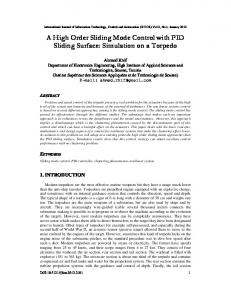
2. SYSTEM DESCRIPTION The figure 1 shows the proposed structure. It is composed of an asynchronous motor powered by a photovoltaic generator and a storage of batteries towards a voltage inverter, controlled by a sliding mode control.
Fig. 1: Diagram bloc of the proposed system
A sliding mode control associated to the field-oriented control of asynchronous motor… 319
3. SIZING OF THE PHOTOVOLTAIC SYSTEM SUPPLIED AN INDUCTION MOTOR For sizing a photovoltaic system, we have to carry out in the first the motor consumption; in hence to define the energy need of the load. After, in the second, we must take in account the obtained results and also the meteorological data as the input parameters of the photovoltaic installation of the input program. The sizing of the photovoltaic system is carried out according to the algorithm bellow as described by Fig. 2, [3].
Fig. 2: The sizing algorithm of the pair (photovoltaic generator-batteries) of the photovoltaic system powered an induction motor 4. MPPT CONTROL To optimize the power provided by the generator, a static converter which operates as an adapter must be added. The Fig. 3 shows the converter which is a boost chopper. It exploits the MPPT technique.
Fig. 3: Boost converter DC/DC
320
L. Barazane et al.
There are many algorithms that are used to control the MPPT. The algorithms that are most commonly used are the perturbation and observation method (P&O), dynamic approach method and the incremental conductance algorithm. The P&O method is used because of its simplicity [5]. Perturbation and observation (P&O) method has a simple feedback structure and fewer measured parameters. It operates by periodically perturbing (incrementing or decreasing) the array terminal voltage and comparing the PV output power with that of the previous perturbation cycle. If the perturbation leads to an increase (decrease) in array power, the subsequent perturbation is made in the same (opposite) direction. In this manner, the peak power tracker continuously seeks the peak power condition as described by the algorithm of the figure 4. The figure 5 shows well that one approaches in each case the maximum power point [1, 4, 5].
Fig. 4: Diagram bloc of the proposed system
Fig. 5: Power – Voltage characteristic
A sliding mode control associated to the field-oriented control of asynchronous motor… 321
5. SLIDING MODE CONTROL The basic principle of sliding mode control consists in moving the state trajectory of the system toward a predetermined surface called sliding or switching surface and in maintaining it around this latter with an appropriate switching logic. This is similar to a feed-forward controller that provides the control that should be applied to track a desired trajectory, which is in this case, the user-defined sliding surface itself. So, the design of a sliding mode controller has two steps, namely, the definition of the adequate switching surface S ( . ) and the development of the control law or the switching logic U . Concerning the development of the switching logic, it is divided into two parts, the equivalent control U eq and the attractivity or reach ability control U n . The equivalent control is determined off-line with a model that represents the plant as accurately as possible. If the plant is exactly identical to the model used for determining U eq and there are no disturbances, there would be no need to apply an additional control U n . However, in practice there will be discrepancy between the model and the actual system control. Therefore, the control component U n is necessary and it will always guarantee that the state is attracted to the switching surface by satisfying the condition S ( . ) . S& ( . ) < 0 [11, 13]. Therefore, the basic switching law is of the form:
U = U eq + U n with
(1)
U n = − M ( . ) . sgn ( S ( . ) ) M ( S ) : the magnitude of the attractivity control law U n ,
Sgn : the sign function. In a conventional VSC, the reachability control generates a high control activity as it depends on the magnitude M ( . ) since it was first taken as constant, a relay function, which is very harmful to the actuators and may excite the unmodeled dynamics of the system. This is known as a chattering phenomenon. Ideally, to reach the sliding surface, this phenomenon should be eliminated [16]. However, in practice, chattering can only be reduced. To reduce chattering was to introduce a boundary layer around the sliding surface and to use a smooth function to replace the discontinuous part of the control action as follows [11, 13]: ⎧K ⎪ . S( x ) Un = ⎨ ε ⎪⎩K . Sgn ( S ( x ))
if
S( x ) < ε
if
S( x ) > ε
(2)
The constant K is linked to the speed of convergence towards the sliding surface of the process the reaching mode). Compromise must be made when choosing this constant, since if K is very small the time response is important, whereas when K is too big the chattering phenomenon increases.
6. CONTROL OF AN INDUCTION MOTOR 6.1 Model of the induction motor The equations of the voltage PWM source inverter fed induction motor with current control, in the synchronous reference frame ( d − q ), using rotor fluxes as state variables are given by:
For a rotor-flux orientation, the regulator imposes the orientation of the rotor flux ( Φ ) with respect to the d -axis, giving Φ r = Φ dr and Φ qr = 0 . Substituting these Relations in (6), leads to the field-oriented model of the motor which is given by the following equation system:
322
L. Barazane et al.
d i ds L + R s i ds − σ L s ωs i qs − m ωr Φ qr dt Tr d i qs Lm ν qs = σ L s + R s i qs + σ L s ωs i ds − ωr Φ dr dt Tr d φ dr 1 ( Φ dr − L m .i ds ) + ωsl × Φ qr = − dt Tr d φ qr 1 = − Φ qr − L m .i qs + ωsl × Φ dr dt Tr
ν ds = σ L s
(
)
dΩ 1 = × ( Tem − TL − f r . Ω ) dt J 3 p Lm Tem = . Φ dr .i qs − Φ qr .i ds 2 Lr
(
(3)
)
The field-oriented controller is based on the inversion of the above equation system. The command variables ( i*ds , i*qs , v*ds , i*qs ) are generated here respectively by the sliding mode controllers (SMC1), (SMC2), (SMC3) and (SMC4) as it is shown in figure 6.
Fig. 6: Block diagram of the speed regulator ν ds = σ L s
d i ds L + R s i ds − σ L s ωs i qs − m ωr Φ r dt Tr
ν qs = σ L s
d i qs dt
+ R s i qs + σ L s ωs i ds −
d Φ *r L 1 * + . Φ r = m .i*ds dt Tr Tr ω*sl =
Lm ωr Φ r Tr
(4)
L m . i*qs Tr . Φ *r
3 p Lm * * Φ r . i qs 2 Lr The rotor flux is estimated by means of stator current and speed measurements (direct method) as follows: * Tem =
A sliding mode control associated to the field-oriented control of asynchronous motor… 323 2 ⎡ ⎛ ⎛L ⎞ ⎞ d i ds L 1 ⎢ . ν ds − ⎜⎜ R s + ⎜⎜ m ⎟⎟ ⎟⎟ . i ds + σ L s ωs i qs + m ωr Φ r = dt σ Ls ⎢ T Tr ⎜ ⎟ ⎝ r ⎠ ⎠ ⎢⎣ ⎝ 2 ⎡ ⎛ d i qs ⎛L ⎞ ⎞ L 1 ⎢ . ν qs − ⎜⎜ R s + ⎜⎜ m ⎟⎟ ⎟⎟ . i qs + σ L s ωs i ds + m ωr Φ r = dt T Tr σ Ls ⎢ ⎜ ⎟ r ⎠ ⎠ ⎝ ⎢⎣ ⎝ The corresponding position is given by:
θe =
⎤ ⎥ ⎥ ⎥⎦ ⎤ ⎥ ⎥ ⎥⎦
∫ ( p . Ω + ωsl ) . d t *
(5)
(6)
6.2 Sliding mode control The proposed control scheme is a cascade structure as it is shown in figure 3, in which four surfaces are required. The internal loops allow the control of the stator current components ( i ds ,
i qs ), whereas the external loops provide the regulation of the speed Ω and the rotor flux Φ r . 6.2.1 Design of the switching surfaces In this work, four sliding surfaces are used and taken as follows since a first order model is used [18]:
S ( Ω ) = ( Ω ref − Ω ) + m1 . ∫ ( Ω ref − Ω ) d t S( Φ r
)=
S ( i ds
)=
( Φ r, ref − Φ r ) + m 2 . ∫ ( Φ r, ref − Φ r ) d t
(i S ( i ) = (i qs
) ( ) + m . ∫ (i
) )dt
* ds
− i ds + m 3 . ∫ i*ds − i ds d t
* qs
− i qs
4
* qs
− i qs
(7)
with Ω ref and Φ r , ref being respectively the reference variables of the rotor speed and the
flux. S ( Ω ) , S ( Φ r
)
are related to the outer loops, whereas S ( i ds
) and
( )
S i qs are related to the
inner loops. The i*ds and i*qs references are determined by the outer loops, and take respectively the values of the control variables i ds and i qs . 6.2.2 Development of the control laws By using the equation systems (1) and (2), the regulators control laws are obtained as follows:
- For the flux regulator S ( Ω ) . S& ( Ω ) < 0 With
i dseq =
⇒
i ds = i dseq + i dsn
(8)
& Tr . Φ r , ref + Φ r
Lm
⎧ Kf . S( Φ r ) ⎪ i dsn = ⎨ ε f ⎪K f . Sgn ( S ( Φ r ⎩ - For the speed regulator S ( Ω ) . S& ( Ω ) < 0 ⇒
))
if
S( Φ r
)
< εf
if
S( Φ r
)
> εf
i qs = i qseq + i qsn
(9)
324
L. Barazane et al.
d Ω ref + TL dt 3 Lm p . Φr 2 Lr
J. With
i qseq =
⎧ Kω . S( Ω ) ⎪ i qsn = ⎨ ε ω ⎪K ω . Sgn ( S ( Ω )) ⎩
if
S( Ω ) < εω
if
S( Ω ) > εω
The two regulators control laws, for the control variables i ds and i qs , of the internal loops are given by: - For the control variable i ds S ( i ) . S& ( i ) < 0 ⇒ ds
With
ds
ν dseq = σ L s
ν ds = ν dseq + ν dsn
(10)
d i ds L + R s i ds − σ L s ωs i qs − m ωr Φ r dt Tr
⎧ Kd . S ( i ds ) ⎪ ν dsn = ⎨ ε d ⎪K d . Sgn ( S ( i ds ⎩
))
if
S ( i ds
)
< εd
if
S ( i ds
)
> εd
- For the control variable i qs
( ) ( )
S i qs . S& i qs < 0
With
ν qseq = σ L s
ν qsn
⇒
d i qs dt
ν qs = ν qseq + ν qsn
+ R s i qs + σ L s ωs i ds +
⎧ Kq . S i qs ⎪ = ⎨ εq ⎪K . Sgn S i qs ⎩ q
( ) ( ( ))
if if
(11)
Lm ωr Φ r Tr
( ) < εq S ( i qs ) > ε q
S i qs
To satisfy the stability condition of the system, the gains K f , K ω , K d and K q should be taken positive by selecting the appropriate values.
7. VALIDATION OF THE CASCADE SLIDING MODE CONTROLLERS A cascade structure with sliding mode control of the rotor flux oriented control has been simulated using the parameters given in Appendix. The first test concerns a no-load starting of the motor with a reference speed Ω ref = 100 rad/sec. Then a torque load ( TL = 10 Nm) is applied at t = 0.5 sec . The results are shown in figure 6.
It is noticed that the speed regulation is obtained using such a controller is spite of the presence of stern disturbances such as step change of the load torque. The waveforms depicted in figure 5 show that the ideal field-oriented control is established by setting the flux responses Φ qr = 0 , Φ dr = 1 Wb , despite the load variations. The step changes in the load torque and the reverse of speed response cause step changes in the torque response without any effects on the fluxes responses, which are maintained constant, due to the decoupled control system between the torque and the rotor flux. Thus, the aim of the field-oriented control is achieved, and the introduction of perturbations is immediately rejected by the control system.
A sliding mode control associated to the field-oriented control of asynchronous motor… 325
Fig. 6: Simulation results for a cascade structure using fuzzy SMCs The chattering phenomenon appears in the torque response due to the discontinuous characteristic of the controller. The aim of the second test is to solve the problem of detuning in indirect field-orientation control system in the case of parameter variations of the motor. The coefficients in (7) are all dependent on the motor parameters. These parameters may vary during online operation due to temperature or saturation effects. So, it is important to investigate the sensitivity of the complete system to parameters' changes. One of the most significant parameter changes in the motor is the rotor resistance R r . A simulation taking into account the variation of 20 % rise of R r relative to the identified model parameter was carried out. The parameters' changes are introduced only in the model of the motor. Neither the estimator, nor the controller is involved by this variation. The waveforms obtained are illustrated in figure 7.
Fig. 7: Simulation results for a cascade structure using SMCs The responses are approximately similar to those obtained in figure 8 and the condition of oriented control is obtained in the steady state ( Φ qr = 0 ).
326
L. Barazane et al.
It can be conclude that the proposed sliding controllers are robust. They are able to realise and maintain the control even the parameters of the motor ( R r ) change.
Fig. 8: Simulation results with variation of 20% of R r for an indirect FOC drive with SMCs
8. CONCLUSION The cascade sliding mode control of the field oriented induction motor fed by photovoltaic generator was proposed. This allows the extendibility of the applicability of the studied system, particularly in the space vehicles, solar vehicles and also in the case of the pumping of water. To show the effectiveness and performances of the developed control scheme, a simulation study was carried out. Good results were obtained despite the simplicity of the chosen sliding surfaces. The robustness and the tracking qualities of the proposed control system using sliding mode controllers appear clearly.
9. APPENDIX: MACHINE PARAMETERS Squirrel-cage induction motor of 1.5 kW, 220 V, 2 poles, 1420 tr/min, 50 Hz. R s = 4.85 Ω ; R r = 3.805 Ω ; L s = 0.274 H ; L r =0.274 H. M = 0.258 H ; J = 0.031 kg.m2 ; f = 0.00114 Nms.
REFERENCES [1] R. Issad et D. Rekioua, ‘Commande Directe du Couple d’une Machine Asynchrone Alimentée par un Générateur Photovoltaïque’, Colloque National sur l’Energie Solaire, Proceedings, pp. 130 – 135, Nov. 2006. [2] A. Betka and A. Moussi, ‘Optimized Solar Water Pumping System Based on an Induction Motor Driving a Centrifugal Pump’, Colloque National sur l’Energie Solaire, Proceeding, pp. 107 – 112, Nov. 2006. [3] S. Kharzi, M. Haddadi and A. Malek, ‘Survey of the Cathodic Protection Device Supplied by Photovoltaic Solar Energy’, 21st European Photovoltaic Solar Energy Conference, Proceedings., pp. 3071 - 3077, Dresden, Germany, 2006 [4] S. Kharzi, ‘Etude d’un Dispositif de la Protection Cathodique Alimenté par Energie Solaire Photovoltaïque’, Mémoire de Magister, Ecole Nationale Polytechnique, El-Harrach, Alger, Algérie, 2005. [5] T. Phu Nguyen, ‘Solar Panel Maximum Power Point Tracker’, Undergraduate Thesis, University of Queensland, Oct. 2001.
A sliding mode control associated to the field-oriented control of asynchronous motor… 327 [6] B.K. Bose, ‘Technology Trends in Microcomputer Control of Electrical Machines’, IEEE Trans. Ind. Electron, Vol. 35, N°1, pp. 160 – 177, Feb. 1988. [7] F. Blaschke, ‘The Principle of Field Orientation as Applied to the New Transvector’, Siemens Review, Vol. 34, pp. 217 – 222, May 1972. [8] L. Barazane, ‘Commande Vectorielle d’un Moteur Asynchrone Alimenté en Courant’, Thèse de Magister, ENP, Alger, Algérie, 1993. [9] L. Barazane et B. Hemici, ‘Etude de l’Influence de la Constante de Temps Rotorique et de la Saturation sur la Commande Vectorielle de la Machine Asynchrone Alimentée en Courant’, 3rd International Conf. On Applied Math. & Engin., CIMASI’2000, Casablanca, Maroc, 2000. [10] L. Barazane, Y. Sellami and S. Boukhalfa, ‘Speed Controller of Field-Orientated Control of an Induction Motor Using an Artificial Neural Network’, CARI'2000, Antananarivo, Madagascar, 13-15 Oct. 2000. [11] J.J. Slotine and W. Li, ‘Applied Nonlinear Control’, Englewood Cliffs, N: Prentice Hall, 1991. [12] H.X. Li, H.B. Gatland and A.W. Green, ‘Fuzzy Variable Structure Control’, IEEE Trans. Syst. Man Cybern., Part B, Vol. 27, N°2, pp. 306 – 312, April 1997. [13] H.A. Hsu and H.A. Malki, ‘Fuzzy Variable Structure Control for MIMO Systems’, IEEE Int. Conf. Fuzzy Syst. Proc., Vol. 1, pp. 280 – 285, 1998. [14] V.I. Utkin, ‘Sliding Mode Control Design. Principles and Application to Electrical Derives’, IEEE Trans. Ind. Electron., pp. 23 – 26, 1993. [15] G. Bartolini, M. Marchesoni, P. Pisu and E. Usai, ‘Chattering Reduction and Robust Position Control in Induction Motor with Second-Order VSS’, International Journal of Systems Science, Vol. 29, N°1, pp. 1 – 12, 1998. [16] H. Sira-Ramirez, ‘A Geometric Approach to Pulse-Width-Modulated Control Design’, Proc. 26th IEEE Conf. Decision and Control, Los Angeles, CA, Dec. 1987.