Hindawi Publishing Corporation Advances in Fuzzy Systems Volume 2013, Article ID 343174, 12 pages http://dx.doi.org/10.1155/2013/343174
Research Article A Soft Computing Approach to Crack Detection and Impact Source Identification with Field-Programmable Gate Array Implementation Arati M. Dixit1 and Harpreet Singh2 1 2
Department of Computer Engineering, Defence Institute of Advanced Technology (DU), Girinagar, Pune 411025, India Department of Electrical & Computer Engineering, Wayne State University, Detroit, MI 48202, USA
Correspondence should be addressed to Arati M. Dixit;
[email protected] Received 30 July 2012; Accepted 3 October 2012 Academic Editor: Thomas Meitzler Copyright © 2013 A. M. Dixit and H. Singh. This is an open access article distributed under the Creative Commons Attribution License, which permits unrestricted use, distribution, and reproduction in any medium, provided the original work is properly cited. The real-time nondestructive testing (NDT) for crack detection and impact source identification (CDISI) has attracted the researchers from diverse areas. This is apparent from the current work in the literature. CDISI has usually been performed by visual assessment of waveforms generated by a standard data acquisition system. In this paper we suggest an automation of CDISI for metal armor plates using a soft computing approach by developing a fuzzy inference system to effectively deal with this problem. It is also advantageous to develop a chip that can contribute towards real time CDISI. The objective of this paper is to report on efforts to develop an automated CDISI procedure and to formulate a technique such that the proposed method can be easily implemented on a chip. The CDISI fuzzy inference system is developed using MATLAB’s fuzzy logic toolbox. A VLSI circuit for CDISI is developed on basis of fuzzy logic model using Verilog, a hardware description language (HDL). The Xilinx ISE WebPACK9.1i is used for design, synthesis, implementation, and verification. The CDISI field-programmable gate array (FPGA) implementation is done using Xilinx’s Spartan 3 FPGA. SynaptiCAD’s Verilog Simulators—VeriLogger PRO and ModelSim—are used as the software simulation and debug environment.
1. Introduction Crack detection and impact source identification in materials is a renowned problem found in variety of commercial and military applications like beams, bridges, turbines, pavements, armor plates, vehicle body plates, bones, teeth, and so on. This long-standing interest in development of CDISI is evident from variety of methods proposed in the literature [1– 33]. Ultrasonic guided waves are used for the crack detection [1, 2]. The crack detection is done by measuring lamb wave signals using the dual PZT transducers [3]. Wireless inductively-coupled transducers are used for the crack detection [4]. The wave velocities of concrete are measured by the portable transient elastic wave system to track the health of concrete [5]. Automation for different crack detection and impact source identification methods is lately carried out
in the literature using soft computing and VLSI techniques. Image processing techniques are used for the crack detection [6, 7]. One of the most effective tools to deal with complex problems with lack of certainty, accuracy, and absolute truth is the soft computing. Zadeh [8] describes soft computing “Soft computing is tolerant of imprecision, uncertainty, partial truth, and approximation than the traditional Hard Computing. The role model for soft computing is the human brain.” A fuzzy inference system [9] is developed to predict location and depth of the crack of a cracked cantilever beam structure in a close proximity to the real results. A hybrid artificial intelligence technique with fuzzy-neuro controller is used to detect the crack with its location in cantilever beam [10]. Fuzzy logic and expert system techniques are efficiently used in evaluation of pavement distress like cracking [11]. A genetic fuzzy system [12] is used for crack density and crack location
2
Advances in Fuzzy Systems
Variable AC source
Oscilloscope
PZT transducers/ sensor B
PZT transducers/ sensor A Ceramic armor plate
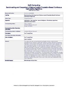
Figure 1: CDISI: crack detection test system circuit.
detection. The genetic fuzzy logic system [13] is used as method for automatic rule generation in fuzzy systems for structural damage detection. Reference [14] has presented a comprehensive structural fault detection method using fuzzy logic which is better suited to tolerate noise and uncertainty. A fuzzy rule-based system [15] is developed for the blade of a BO-105 helicopter rotor modeled as a cantilever beam and demonstrated that the fuzzy system performs accurately even in the existence of noisy data. The sensitivity of the modal frequencies and other parameters to a crack increases when the crack is near the sensors and decreases as the crack moves away, thus a modular neural network architecture [16] is presented as a nondestructive method for health monitoring of structures. The issue of uncertainty in material properties in structural damage detection with fuzzy logic is addressed by [30–33], with use of the fuzzy cognitive maps [30] used to solve this problem. Recently Meitzler et al. [1] have proposed an ultrasonic crack detection system, which uses transducers to detect the crack in metal armor plates. The existence of cracks is determined by comparing the output voltage waveforms with those of an undamaged plate manually using metrics. NDT of an object determines its usefulness without ruining it to avoid its intended use. A CDISI problem is quite important to issues related to the security and safety of soldiers as it affects the armored vehicles’ body plates and soldier’s body armor on the battlefield. The NDT for CDISI accomplishes to perk up the reliability by assuring the quality level of armor material and operational readiness of armored vehicles and soldier’s body armor plate prior to or during its day-to-day use. A CDISI system for armor plates is presented as a new soft computing method based on the fuzzy logic component. The FPGA implementation [1] of CDISI fuzzy inference system is done with an intention to embed it on a chip designed for a CDISI handheld device. Our approach uses the theory of soft computing to develop a model supported by VLSI design to determine the following metrics. (1) Nature of plate: It is diagnosed to be in one of the four possible states like unknown, undamaged, slightly damaged, and damaged. The system generates degree of crack value in the range of [0, 1] where 0 represents an unknown state and 1 represents a damaged plate.
As the degree of crack value increases, the amount of crack in the plate also increases. (2) Source of impact: The CDISI system currently recognizes two different sources of impact. This can be expanded for incorporation of a larger range of sources. This paper is organized in the following manner. Section 2 focuses on the literature review and discusses the CDISI system description. Section 3 discusses the fundamental theory of fuzzy systems, fuzzy models, and fuzzy logic-based modeling techniques for CDISI. The proposed CDISI fuzzy inference system is given in Section 4. Section 5 presents FPGA implementation of CDISI system. An integrated approach of CDISI system which is based on the Fuzzy model and FPGA implementation is the topic of discussion in Section 6. Finally Section 7 concludes the paper.
2. CDISI System Description Crack detection and impact source identification has been a widely studied problem in the literature using NDT approaches. The work of Meitzler et al. [1] is reviewed here for the ready reference. An ultrasonic crack detection system [1] for ceramic vehicle body armor support system (VBASS) plates as shown in Figure 1 uses two piezoelectric lead zirconate titanate (PZT) transducers attached with ceramic plate to be tested for the crack. Generally transducers are used to transmit energy from one type to another. Here they are used to stimulate and measure the resonances mode of rectangular ceramic armor plates in 50–300 kHz range of frequencies. PZT transducer/sensor A is connected to the variable AC source, and the PZT transducer/sensor B is connected to the oscilloscope for transmitted energy and excited vibrational mode analysis. The alteration in the mechanical structure or presence of cracks is determined by comparing the output voltage waveforms with those of an undamaged plate manually using metrics. The impact source identification system consists of a ceramic plate [17, 18] as shown in Figure 2. The two sensors, sensor A and sensor B, are positioned on two sides of the ceramic plate which sense the acoustic emissions from submicron cracking caused by the hitting pressure. These
Advances in Fuzzy Systems
3 P00 Oscilloscope Sensor A
P01
P02
P03
P10 P11 P12 P13 P20
P21 P22
P23
Sensor B Oscilloscope
P30 P31 P32 P33
Figure 2: CDISI: impact source identification test system circuit.
sensors read the waveforms when the plate is hit by the source. The data acquisition system (DAS) extracts data from these waveforms. The location being hit on the plate affects the decision of impact source identification, so it has 16 parts where the source can be hit. These parts are labeled P00 to P33 as seen in Figure 2. The accuracy of the identification of the source of impact depends on the part number being hit by a source. An automated procedure for the CDISI is proposed, which reads the waveforms from the sensors A and B in the test circuits seen in Figures 1 and 2 with the help of a DEWESoft data acquisition [19] system. The various parameters extracted from the CDISI system waveforms are frequency, average RMS, standard deviation, RMS value, peak value, median, mode, and FFT value. After systematic study of parameters it was noticed that some of these parameters are instrumental in the process of decision making towards conclusion = {Nature of plate, Source of Impact} and some are redundant. The unique parameters extracted from sensors A and B for the CDISI assessment are input frequency, average RMS, standard deviation, location index, Arms, Amax, Brms, and Bmax. The Arms and Brms are the RMS value for sensors A and B. Amax and Bmax are the peak value for the sensors A and B. The details of the input and output parameters of the CDISI are Input Parameters = {Input Frequency, Average RMS, Std. Deviation, Location Index, Arms, Amax, Brms, Bmax} ,
(a)
Output Parameters = {Nature of Plate, Source of Impact} , (b) Nature of Plate ={Unknown, Undamaged, Damaged, Slightly Damaged} , (c) Source of Impact = {SourceType1, SourceType2, SourceUnknown} .
(d)
The CDISI test circuits as shown in Figures 1 and 2 generate a sufficiently large database for {Input Parameters, Output Parameters}. This database is influential in defining fuzzy relation between the inputs and output parameters.
In practice the time and frequency domain analysis of the sensor waveforms is used for CDISI, which many times turns out to be very expensive. To the best of authors knowledge fuzzy logic is the best candidate to express the relation between the input and the output parameters, due to the lack of strong mathematical model to represent this system. CDISI fuzzy system outperforms the conventional comparison method involving human error due to manual comparison of the waveforms with that of an ideal plate and the known source of impact. The CDISI fuzzy inference system is a fast, reasonably priced faultdiagnosis solution in the complex system which involves human thinking. The CDISI fuzzy model is discussed in Section 3.
3. CDISI Fuzzy Model A fuzzy system is developed on the basis of the fuzzy logic, which is based on the fuzzy set theory [9]. Fuzzy logic supports approximate reasoning by taking a broader view of Boolean values of 1 and 0 with fine merger of symbolic and numeric computation. All the input and output parameters in a fuzzy system are essentially fuzzy-subset [20] with each element having some degree of membership in the subset. The CDISI fuzzy system model portrayed in Figure 3 consists of following elements. (1) Numerical Data Inputs. The numerical values for all input parameters are extracted from the output waveforms generated with the help of data acquisition system. These numerical values for different parameters are used as inputs to CDISI fuzzy model. The numerical data inputs for CDISI system are input frequency, average RMS, standard deviation, location index, Arms, Amax, Brms, and Bmax. (2) Numerical and Linguistic Data Outputs. The CDISI output waveform parameters lead to determine the nature of plate and the source of impact. The nature of plate ∈ [0, 1] is also represented as degree of crack; the smaller the value of degree the less the amount of cracking. The linguistic labels applied to the output parameters are (i) NatureOfPlate ∈ {Unknown, Undamaged, Slightly Damaged, Damaged} ∈ [0, 1], (ii) SourceOfImpact ∈ {SourceType1, SourceType2, SourceUnknown} ∈ [0, 1].
4
Advances in Fuzzy Systems CDISI system knowledge base
Fuzzy inference engine
Fuzzification
Numerical data inputs
Defuzzification
Numerical, linguistic output
Frequency
Amax
Average RMS
Arms
Std. deviation
Bmax
Location
Brms
Degree of crack
Source of impact
Figure 3: CDISI fuzzy system model.
Table 1: Linguistic labels for the index location parameter. Parameter Index location segments
Labels Near Segments adjacent to sensor
Far Segments adjacent sidewise to the near section
Faraway Rest of the segments
(3) Fuzzification. It maps observed nonfuzzy input parameters into suitable linguistic values, which are defined as the labels of fuzzy parameter sets. The linguistic labels for input parameter location index can be seen in Table 1. The near label segments are shaded grey, far label segments are white, and faraway label segments are shaded in gradient in Figure 2. The linguistic labels for input parameters input frequency, average RMS, std. deviation, Arms, Amax, Brms, and Bmax can be illustrated in Table 2. The transformation of data into linguistic labels and vice versa is done with help of (1) and (2) and Table 3. LL if 01 ≤ 𝑥 < 30, { { { { LH if 30 ≤ 𝑥 < 60, { { { { { ML if 60 ≤ 𝑥 < 70, { { Frequency (𝑥) = {MH if 70 ≤ 𝑥 < 80, { { { HL if 80 ≤ 𝑥 < 90, { { { { { { {HH if 90 ≤ 𝑥 < 100, {VH if > 110.
(1)
In (1) label is allocated to different values of the input frequency. These labels are further associated with membership functions from Table 3 equations for the different values of the linguistic labels used in the fuzzy model. (4) Fuzzy Inference Engine. The major components of this block are (a) a rule base: fuzzy rule can be expressed as
“If input1 is A or input2 is B and input3 is C, then output is D,” where A, B, and C are the input and D is output linguistic label values defined. With some experimentation, trialerror, past experience, and familiarity with the system that is to be developed the rules are formulated; (b) fuzzy rule database: sets up the relation and defines the membership functions for each input and output parameter being used by the CDISI fuzzy rules; (c) reasoning mechanism: this block generates the result by implementing the inference procedure on the given conditions and the formed rules. Different reasoning mechanisms can be used in a fuzzy system to obtain the desired result. The CDISI results are obtained by aggregating the result of each rule in the fuzzy rule base. (5) Defuzzification. This component takes inputs as aggregated fuzzy dataset, the result of fuzzy inference engine and further maps it to a nonfuzzy output value for the degree of crack/nature of plate and source of impact outputs. The reverse process of the fuzzification is SourceOfImpact (𝑥) if trimf (𝑥, [−0.4, 0, 0.4]) , SrcType1 { { = {SrcType2 if trimf (𝑥, [1, 0.5, 0.9]) , { {SrcUnknown if trimf (𝑥, [0.6, 1, 1.4]) , NatureOfPlate (𝑥) UnKnown if trimf (𝑥, [−0.3333, 0, 0.3333]) { { { {Undamaged if trimf (𝑥, [0, 0.3333, 0.6667]) ={ { Slightly Damaged if trimf (𝑥, [0.3333, 0.6667, 1]) { { if trimf (𝑥, [0.6667, 1, 1.333]) , {Damaged (2)
Advances in Fuzzy Systems
5 Table 2: Linguistic labels for the different parameters.
Labels Range of value
LL Low-low
LH Low-high
ML Medium-low
MM Medium-medium
Table 3: Linguistic label membership function equations for different parameters. Membership function equations 0, 𝑥 ≤ 0, { { { LL(𝑥) = {0.1429 − 𝑥/0.1429, 𝑥 ∈ (0, 0.1429) , { { {0, 𝑥 ≥ 0.1429. 0, 𝑥 ≤ 0.1429 { { { { { {𝑥/(0.1429), 𝑥 ∈ (0, 0.1429) , LH(𝑥) = { { { 0.3 − 𝑥/0.1428, 𝑥 ∈ (0.1429, 0.2857) , { { { {0, 𝑥 ≥ 0.2857. 0, 𝑥 ≤ 0.1429, { { { { { {𝑥 − 0.1429/0.1428, 𝑥 ∈ (0.1429, 0.2857) , ML(𝑥) = { { { 0.2857 − 𝑥/0.1429, 𝑥 ∈ (0.2857, 0.4286) , { { { 0, { 𝑥 ≥ 0.4286. 0, 𝑥 ≤ 0.2857, { { { { { {𝑥 − 0.2857/0.1429, 𝑥 ∈ (0.2857, 0.4286) , MM(𝑥) = { { { 0.4286 − 𝑥/0.1428, 𝑥 ∈ (0.4286, 0.5714) , { { { {0, 𝑥 ≥ 0.5714. 0, 𝑥 ≤ 0.4286, { { { { { {𝑥 − 0.4286/0.1428, 𝑥 ∈ (0.4286, 0.5714) , MH(𝑥) = { { { 0.5714 − 𝑥/0.1429, 𝑥 ∈ (0.5714, 0.7143) , { { { {0, 𝑥 ≥ 0.7143. 0, 𝑥 ≤ 0.5714, { { { { { {𝑥 − 0.5714/0.1429, 𝑥 ∈ (0.5714, 0.7143) , HL(𝑥) = { { { 0.7143 − 𝑥/0.1428, 𝑥 ∈ (0.7143, 0.8571) , { { { {0, 𝑥 ≥ 0.8571. 0, 𝑥 ≤ 0.7143, { { { { { {𝑥 − 0.7143/0.1428, 𝑥 ∈ (0.7143, 0.8571) , HH(𝑥) = { { { 0.857 − 𝑥/0.1429, 𝑥 ∈ (0.8571, 1) , { { { {0, 𝑥 ≥ 1. 0, 𝑥 ≤ 0.8571, { { { VH(𝑥) = {𝑥 − 0.8571/0.1429, 𝑥 ∈ (0.8571, 1) , { { {0, 𝑥 ≥ 1.
where trimf(𝑥, [a, b, c]) is the triangular function [21] with a, b, and c as left feet, right feet, and the peaks of triangle.
4. CDISI Fuzzy Inference System Taking into consideration the automation of CDISI system for armor plates and the uncertainties pertaining to these kinds
MH Medium-high
HL High-low
HH High-high
VH Very high
of systems, the fuzzy logic approach [12, 23] seems to be one of the promising candidates. The CDISI Fuzzy Inference System is a multiple input multiple output (MIMO) system as shown in Figure 4. It has eight input and two output unique parameters. The Linguistic labels for the Index Location parameter are tabulated in Table 1 and rest of the input parameters in Table 2. The linguistic labels for the output parameters are expressed in (2). Table 4 shows the labels and range of values for different input parameters. The membership functions are assigned to each of these parameters. All of the CDISI parameter membership functions selected are triangular functions after some trial and error on experimenting with other membership functions like Gaussian, Trapezoidal, Gaussian bell and few more. It was observed that triangular function works well with the CDISI Fuzzy Inference System. Figure 5 shows the triangular membership function for the output parameters NatureOfPlate and SourceOfImpact. Figure 6 shows the triangular membership function for the input parameters like Average RMS and Location. Table 5 shows a sample of the rule base, expressing the relationship between the input and output parameters. If any of the input parameter labels are “true” for a certain rule then that rule is said to be activated. About five dozen rules are incorporated in the CDISI System. Fuzzy Logic Toolbox from MATLAB is used to build the CDISI fuzzy Inference System using Mamdani method [21]. The CDISI Fuzzy Inference System implementation snapshots can be seen in Figure 7. Figure 7(a) shows the MIMO structure of the CDISI Fuzzy Inference System. This portrays the input and the output parameters as discussed in Sections 2 and 3. A snapshot of CDISI Fuzzy System Rule Editor Window can be seen in Figure 7(b), which provides an environment to add, delete and update rules in the rule database.
5. FPGA Implementation of CDISI CDISI system automation is done by rapid prototyping of a chip with the help of FPGA implementation [24–26]. The reference [1] has discussed the standalone device designed to detect cracks in armor plates. An effort is made to develop a chip which can detect crack and identify the source of impact on basis of logic used in the CDISI fuzzy inference system discussed in Section 4. FPGA implementation of the CDISI system is done using hardware description language Verilog with the Xilinx ISE WebPack [27], SynaptiCAD [28], and ModelSim XE [29] using Spartan 3 FPGA. CDISI FPGA implementation is a general-purpose, multi-level programmable logic device supported with advantages like (1) flexibility to change rules on the hardware,
Arms Amax Brms Bmax Frequency (KHz) Avg. RMS voltage Standard deviation
Range
LL 0.1–1.1 0–6.5 0–1.5 0–10 1–30 0–0.001 ≤0.00003
LH 1.1–1.4 6.5 1.5–2.4 10 30–60 0.001–0.00199 0.00003–0.00003229
ML 1.4–1.7 6.5–8 2.4–2.9 10–13 60–70 0.00199–0.00225 0.00003229–0.00006229
Labels MM 1.7–1.9 8 2.9 13 70–80 0.00225–0.00250 0.00006229–0.0001 MH 1.9–2.3 8–10 2.9–3.3 13–15.4 80–90 0.00250–0.002971 0.0001–0.0001889
Table 4: Labels for the input function of CDISI fuzzy inference system. HL 2.3–3.5 10 3.3 15.4 90–100 0.002971–0.003111 0.0001889–0.000199
HH 3.5–4 10–17 3.3–4.0 15.4–17 100–110 0.003111–0.004 0.000199–0.00021
VH >4 >17 >4 >17 >110 >0.004 >0.00021
6 Advances in Fuzzy Systems
Advances in Fuzzy Systems
7 Table 5: Sample rule base for the CDISI fuzzy inference system.
Rule no. 1 5 18 35 42 54
Freq MM MM MM HH HH MM
Avg. RMS MM MM MM LL HH HH
Std. dev. MM MM MM HH MM LL
Loc. Far Faraway Near Far Far Far
Arms HL HL VH MM MM MM
Amax HH HH HH MM MM MM
Brms LH MH ML MM MM MM
Bmax ML ML MH MM MM MM
Nature of plate Unknown Unknown Unknown Damaged Undamaged Slightly damaged
Impact source SourceType2 SourceType1 SourceType1 SourceUnknown SourceUnknown SourceUnknown
Input frequency Average RMS voltage Standard deviation Amax Arms Bmax Brms Location index
Degree of crack / nature of plate
CDISI fuzzy inference model
Source of impact
Figure 4: CDISI fuzzy inference system.
1
Unknown
Undamaged
Slightly Damaged Damaged
1
Source Type1 Source Type2 Source Unknown
0.5
0.5
0
0 0
0.1
0.2
0.3 0.4 0.5 0.6 0.7 0.8 Output variable “Nature Of Plate”
0.9
0
1
0.1 0.2 0.3 0.4 0.5 0.6 0.7 0.8 0.9
1
Output variable “Source Of Impact”
(a)
(b)
Figure 5: Output parameters membership function: (a) NatureOfPlate and (b) SourceOfImpact.
LL
1
LH
ML
MM
MH
HL
HH
VH
1
Near
Far
Faraway
0.5
0.5
0
0 0
0.1
0.2
0.3
0.4
0.5
0.6
0.7
Input variable (average RMS)
(a)
0.8
0.9
1
0
0.1 0.2 0.3 0.4 0.5 0.6 0.7 0.8 0.9 Input variable (location)
(b)
Figure 6: Input parameters membership functions: (a) average RMS and (b) location.
1
8
Advances in Fuzzy Systems
Average RMS
Std. deviation
Frequency
CDISI 8 Nature of plate
Location (Mamdani) Arms
Amax
Brms Source of impact Bmax
(a)
(b)
Figure 7: CDISI fuzzy inference system: (a) the fuzzy inference system (FIS) and (b) the FIS rules.
(2) programing and reprograming using reasonably priced hardware and software on the field, (3) cheaper option over the respective chip, with respect to the manufacturing cost and complexity of the chip. Figures 8(a) and 8(b) show the structure of CDISI FPGA system and the RTL schematic, respectively. The system has the following 3-bit inputs: Input Frequency, Average RMS, Standard Deviation, Amax, Arms, Bmax, and Brms. The input Location Index is the only 2-bit input parameter. The output is restricted for the experimental purpose to 1-bit ImpactSource and 2-bit Pltstatus for source of impact and the nature of plate, respectively. The number of bits can be extended further to expand the input and the output domains. The status code bits, that represent the meaning associated with each numerical value result are tabulated in Table 6. They show the
value of output bus. For example, Pltstatus = 11 indicates that the plate is damaged, and ImpactSource = 1 indicates that the source of impact is ImpactSource-Two. Table 7 shows the CDISI FPGA implementation input status code bits for various 3-bit and 2-bit input parameters. This table has tabulated the possible input values that can be assigned to different input buses. CDISI system technology schematic can be seen in Figure 9(a), which represents the design in terms of logic elements optimized to the target device. Figure 9(b) shows the detailed system register transfer level (RTL) schematic of the proposed CDISI system. RTL schematic view symbolizes design in terms of macro blocks. Each macro block has combinatorial logic mapping onto elementary logic function gates. Figure 10(a) shows the output HDL log of the software simulation using SynaptiCAD software of the CDISI system developed.
Advances in Fuzzy Systems
9
Input frequency
3 bits
Avg. RMS voltage
3 bits
Amax (2:0) CDISI system
Location index
2 bits
Amax
3 bits
Arms
3 bits
Bmax
3 bits
Brms
3 bits
Arms (2:0) 1 bits
Standard deviation 3 bits
Plt. status (1:0)
Source of impact
Avg. RMS (2:0) Bmax (2:0)
FPGA model structure
2 bits
Nature of plate/ degree of crack
Brms (2:0) Freq (2:0) Loc. index (1:0) Std. dev (2:0)
(a)
Impact source
(b)
Figure 8: CDISI system FPGA implementation: (a) system design structure and (b) RTL schematic.
(a)
(b)
Figure 9: CDISI system: (a) technology schematic and (b) detailed RTL schematic.
Some sample results can be observed here in Figure 10(a) for a set of input parameters. Figure 10(b) shows the waveform simulation for the CDISI system. Table 8 shows the analysis of CDISI system implementation device usage. It can be seen in Table 8 that LUT (Lookup Table) utilization is 1%. Slice, an elementary programmable logic block which includes two 4-input LUTs, two multiplexers, arithmetic logic unit, and two 1-bit registers, has the utilization of 1%. Thus Table 8 illustrates minimal device usage by the CDISI system.
6. CDISI System: An Integrated Approach CDISI System supports an automated and integrated approach towards crack detection and the impact source identification in ceramic plates. This integrated approach consists of CDISI fuzzy inference system and the CDISI fieldprogrammable gate array (FPGA) implementation as shown in Figure 11. The test circuit discussed in Section 2 generates waveforms which can be displayed on an oscilloscope. The test circuit results are further used to extract the data which
10
Advances in Fuzzy Systems Table 6: CDISI FPGA implementation output status code bits.
CDISI output
Nature of Plate status (2-bit) Undamaged Slightly damaged 01 10 1 2
Unknown 00 0
Output bus code Numerical value
Damaged 11 3
Source of Impact (1-bit) ImpactSource-One ImpactSource-Two 0 1 0 1
Table 7: CDISI FPGA implementation input status code bits. Input labels Range of value Input bus code Numerical value
3-bit input parameters LL
LH
Low-low
Low-high
000 0
MM Mediummedium
MH Mediumhigh
001
010
011
100
101
110
111
00
01
11
1
2
3
4
5
6
7
0
1
3
Table 8: Analysis of FPGA implementation of CDISI. Metric Used Available Utilization Number of 4 input LUTs 10 3,840 1% Number of Slices occupied 6 1,920 1% Additional JTAG gate count for IOBs 912 — — Number of bonded IOBs: 19 173 10% Total equivalent gate count for design 66 — —
proceed as input for the CDISI System. The CDISI fuzzy inference system generates the result {Pltstatus, ImpactSource}. CDISI field-programmable gate array (FPGA) implementation utilizes and implements the rule base from fuzzy inference system. The proposed algorithm for an integrated approach towards CDISI consists of following subsystems. (1) CDISI system test circuit parameter extraction: extracts the parameters from the results generated by the circuits discussed in Section 2 with the help of DEWESoft Data acquisition system. (2) CDISI fuzzy inference system: develops CDISI fuzzy inference system which essentially is a multiple-input, multiple-output fuzzy system, based on the behavior extracted from the data. (3) CDISI field-programmable gate array (FPGA) implementation: identifies the inputs and outputs for the CDISI chip, develops Verilog code for CDISI in ceramic plates on Spartan 3 FPGA, and writes a test-bench file to simulate and verify the FPGA implementation. (4) Display output: nature of plate (Pltstatus) and source of impact (ImpactSource) are the two outputs displayed by both the fuzzy and the FPGA implementations.
HL
HH
VH
2-bit input parameters Near Far Faraway
ML Mediumlow
High-low High-high Very-high low medium
high
The detailed proposed algorithm for overall development of CDISI system which consists of the fuzzy inference and FPGA implementation consists of the following steps. (1) Acquire sensors A and B waveforms using DEWESoft 7 data acquisition system (DAS) and save them in two data files. (2) Extract the input parameters from the waveform data obtained by the test circuit discussed in Section 2. (3) Identify the input and output parameters for CDISI fuzzy inference system as seen in Figures 1 and 2. (4) Set the range for the input and output parameters. CDISI parameter range is tabulated in Table 4. (5) Define CDISI fuzzy model [6, 17] using Mamdani type fuzzy inference system, considering absolute values of parameters. (6) Fuzzify the input parameters and map an observed nonfuzzy input space into suitable linguistic values as seen in Tables 1 and 2. (7) Define membership function for each input and output parameter with experimentation. (8) Develop fuzzy rule base on the basis of data collected. (9) The result is obtained by aggregating the result of each rule in the fuzzy rule base for the considered input. (10) Defuzzify the output and map it to nonfuzzy linguistic output values (NatureofPlate) and (SourceOfImpact). (11) Identify number of bits required to represent the CDISI system input and output parameters on a chip as identified for the fuzzy system and determine the dimension of the system structure as observed in Figure 8. (12) Develop Verilog hardware description language code for CDISI system for ceramic plates. (13) Select device as FPGA and assign package pins for CDISI design on FPGA.
Advances in Fuzzy Systems
11
(a)
(b)
Figure 10: CDISI simulation: (a) HDL log and (b) waveform simulation.
CDISI fuzzy inference system
CDISI output Nature of plate Source of impact
CDISI system test circuit
CDISI FPGA implementation
Figure 11: An integrated approach towards CDISI.
(14) Generate a netlist PROM file to be downloaded on the Spartan 3 FPGA. (15) Configure the FPGA and program FPGA; verify the design using input output signal pins/buttons on FPGA. (16) Write a Verilog test-bench file for software simulation and verification of the FPGA implementation. (17) Run the test bench file with help of any of the tools like SynaptiCAD Verilogger Pro and ModelSim.
7. Conclusion The problem of crack detection has aroused interest amongst a large number of investigators because of its importance in a variety of applications. Similarly there has been interest in identifying the source which is responsible for making the crack. In this paper a unified approach for crack detection and the impact source identification is proposed. Because of the importance of the problem it is essential to develop the chip which can have the algorithm for CDISI problem implemented. It is revealed in this paper that the concept of fuzzy logic and the rule base developed by the fuzzy logic can be implemented to solve this problem in industry. The fuzzy rule base can be developed in the form of a Verilog code, which further enables the field-programmable gate array (FPGA) implementation of the suggested technique. The
suggested technique is implemented using Xilinx’s Spartan 3 FPGA and ISE WebPACK 9.1i software. The software simulation and debugging is done by means of SynaptiCAD’s Verilog Simulator—VeriLogger pro—and ModelSim. The proposed FPGA implementation reads the values of input parameters and exhibits the nature of plate and source of impact. The entire algorithm has been successfully implemented for integrated crack detection and impact source identification and can possibly act as a hand held device for the detection of crack and to identify the source of impact. The current CDISI system can be expanded by inclusion of more parameters and extended range for the parameters. The suggested procedure can show the way to the solutions for several other similar problems of interest in the industry.
References [1] T. J. Meitzler, G. Smith, M. Charbeneau et al., “Crack detection in armor plates using ultrasonic techniques,” Materials Evaluation, vol. 66, no. 6, pp. 555–559, 2008. [2] J. Qu, Y. Berthelot, and L. Jacobs, “Crack detection in thick annular components using ultrasonic guided waves,” Proceedings of the Institution of Mechanical Engineers, Part C, vol. 214, no. 9, pp. 1163–1171, 2000. [3] H. Sohn and S. B. Kim, “Development of dual PZT transducers for reference-free crack detection in thin plate structures,”
12
[4]
[5]
[6]
[7]
[8] [9]
[10]
[11]
[12]
[13]
[14]
[15]
[16]
[17]
[18]
[19]
Advances in Fuzzy Systems IEEE Transactions on Ultrasonics, Ferroelectrics, and Frequency Control, vol. 57, no. 1, pp. 229–240, 2010. P. Zheng, D. W. Greve, and I. J. Oppenheim, “Crack detection with wireless inductively-coupled transducers,” in Sensors and Smart Structures Technologies for Civil, Mechanical, and Aerospace Systems 2008, vol. 6932 of Proceedings of SPIE, p. 69321H, San Diego, Calif, USA, March 2008. J. H. Tong and T. T. Wu, “A portable transient elastic wave system for in-situ nondestructive evaluation of concrete,” NDT.Net, vol. 6, no. 6, 2001. J. Zhu, Y. Mae, and M. Minami, “Finding and quantitative evaluation of minute flaws on metal surface using hairline,” IEEE Transactions on Industrial Electronics, vol. 54, no. 3, pp. 1420–1429, 2007. X. Li, S. K. Tso, X. P. Guan, and Q. Huang, “Improving automatic detection of defects in castings by applying wavelet technique,” IEEE Transactions on Industrial Electronics, vol. 53, no. 6, pp. 1927–1934, 2006. L. A. Zadeh, “Fuzzy logic, neural networks, and soft computing,” Communications of the ACM, vol. 37, no. 3, pp. 77–84, 1994. H. C. Das and D. R. Parhi, “Online fuzzy logic crack detection of a cantilever beam,” International Journal of Knowledge-Based and Intelligent Engineering Systems, vol. 12, no. 2, pp. 157–171, 2008. H. C. Das and D. R. Parhi, “Fuzzy-neuro controler for smart fault detection of a beam,” International Journal of Acoustics and Vibrations, vol. 14, no. 2, pp. 70–80, 2009. H. K. Koduru, F. Xiao, S. N. Amirkhanian, and C. H. Juang, “Using fuzzy logic and expert system approaches in evaluating flexible pavement distress: case study,” Journal of Transportation Engineering, vol. 136, no. 2, pp. 149–157, 2010. P. M. Pawar and R. Ganguli, “Matrix crack detection in thinwalled composite beam using genetic fuzzy system,” Journal of Intelligent Material Systems and Structures, vol. 16, no. 5, pp. 395–409, 2005. P. M. Pawar and R. Ganguli, “Genetic fuzzy system for damage detection in beams and helicopter rotor blades,” Computer Methods in Applied Mechanics and Engineering, vol. 192, no. 16– 18, pp. 2031–2057, 2003. J. P. Sawyer and S. S. Rao, “Structural damage detection and identification using fuzzy logic,” AIAA Journal, vol. 38, no. 12, pp. 2328–2335, 2000. R. Ganguli, “A fuzzy logic system for ground based structural health monitoring of a helicopter rotor using modal data,” Journal of Intelligent Material Systems and Structures, vol. 12, no. 6, pp. 397–407, 2001. S. Suresh, S. N. Omkar, R. Ganguli, and V. Mani, “Identification of crack location and depth in a cantilever beam using a modular neural network approach,” Smart Materials and Structures, vol. 13, no. 4, pp. 907–915, 2004. A. M. Dixit, H. Singh, and T. Meitzler, “On development of a VLSI circuit for impact source identification in ceramic plates,” in Modeling and Simulation for Defense Systems and Applications V, vol. 7705 of Proceedings of SPIE, p. 77050H, Orlando, Fla, USA, April 2010. S. Kamthan, H. Singh, A. M. Dixit et al., “Fuzzy logic approach for impact source identification in ceramic plates,” in Proceedings of the International Conference on Artificial Intelligence (ICAI’09), vol. 2, pp. 932–937, CSREA Press, July 2009. DEWESoft, Dewe43 technical reference manual.
[20] L. A. Zadeh, “Fuzzy sets,” Information and Control, vol. 8, no. 3, pp. 338–353, 1965. [21] The MathWorks, Fuzzy Logic Toolbox 2 User’s Guide, 2009. [22] H. Singh, S. Kamthan, A. M. Dixit, A. Mustapha, T. Meitzler, and A. Meitzler, “Fuzzy and neurofuzzy techniques for crack detection in armor plates,” in Proceedings of the International Conference on Modeling, Simulation and Visualization Methods (MSV’08), pp. 298–307, July 2008. [23] J. Yen and R. Langari, Fuzzy Logic: Intelligence, Control and Information, Prentice Hall, New York, NY, USA, 1998. [24] S. Brown and J. Rose, “FPGA and CPLD architectures: a tutorial,” IEEE Design and Test of Computers, vol. 13, no. 2, pp. 42–57, 1996. [25] E. Monmasson and M. N. Cirstea, “FPGA design methodology for industrial control systems—a review,” IEEE Transactions on Industrial Electronics, vol. 54, no. 4, pp. 1824–1842, 2007. [26] D. Kim, “An Implementation of fuzzy logic controller on the reconfigurable FPGA system,” IEEE Transactions on Industrial Electronics, vol. 47, no. 3, pp. 703–715, 2000. [27] Xilinx, The Programmable Logic Data Book, 2000. [28] SynaptiCAD, “BugHunter Pro and VeriLogger simulators,” Version 12, December 2007. [29] Model Technology Incorporated, Start Here for ModelSim SE, 2002. [30] P. Beena and R. Ganguli, “Structural damage detection using fuzzy cognitive maps and Hebbian learning,” Applied Soft Computing Journal, vol. 11, no. 1, pp. 1014–1020, 2011. [31] M. Chandrashekhar and R. Ganguli, “Structural damage detection using modal curvature and fuzzy logic,” Structural Health Monitoring, vol. 8, no. 4, pp. 267–282, 2009. [32] M. Chandrashekhar and R. Ganguli, “Damage assessment of structures with uncertainty by using mode-shape curvatures and fuzzy logic,” Journal of Sound and Vibration, vol. 326, no. 3–5, pp. 939–957, 2009. [33] M. Chandrashekhar and R. Ganguli, “Uncertainty handling in structural damage detection using fuzzy logic and probabilistic simulation,” Mechanical Systems and Signal Processing, vol. 23, no. 2, pp. 384–404, 2009.
Journal of
Advances in
Industrial Engineering
Multimedia
Hindawi Publishing Corporation http://www.hindawi.com
The Scientific World Journal Volume 2014
Hindawi Publishing Corporation http://www.hindawi.com
Volume 2014
Applied Computational Intelligence and Soft Computing
International Journal of
Distributed Sensor Networks Hindawi Publishing Corporation http://www.hindawi.com
Volume 2014
Hindawi Publishing Corporation http://www.hindawi.com
Volume 2014
Hindawi Publishing Corporation http://www.hindawi.com
Volume 2014
Advances in
Fuzzy Systems Modelling & Simulation in Engineering Hindawi Publishing Corporation http://www.hindawi.com
Hindawi Publishing Corporation http://www.hindawi.com
Volume 2014
Volume 2014
Submit your manuscripts at http://www.hindawi.com
Journal of
Computer Networks and Communications
Advances in
Artificial Intelligence Hindawi Publishing Corporation http://www.hindawi.com
Hindawi Publishing Corporation http://www.hindawi.com
Volume 2014
International Journal of
Biomedical Imaging
Volume 2014
Advances in
Artificial Neural Systems
International Journal of
Computer Engineering
Computer Games Technology
Hindawi Publishing Corporation http://www.hindawi.com
Hindawi Publishing Corporation http://www.hindawi.com
Advances in
Volume 2014
Advances in
Software Engineering Volume 2014
Hindawi Publishing Corporation http://www.hindawi.com
Volume 2014
Hindawi Publishing Corporation http://www.hindawi.com
Volume 2014
Hindawi Publishing Corporation http://www.hindawi.com
Volume 2014
International Journal of
Reconfigurable Computing
Robotics Hindawi Publishing Corporation http://www.hindawi.com
Computational Intelligence and Neuroscience
Advances in
Human-Computer Interaction
Journal of
Volume 2014
Hindawi Publishing Corporation http://www.hindawi.com
Volume 2014
Hindawi Publishing Corporation http://www.hindawi.com
Journal of
Electrical and Computer Engineering Volume 2014
Hindawi Publishing Corporation http://www.hindawi.com
Volume 2014
Hindawi Publishing Corporation http://www.hindawi.com
Volume 2014