Abstract. A Software Architecture Supporting Networked Sensors by. Jason Hill. Master of Science in Electrical Engineering and Computer Science. University of ...
A Software Architecture Supporting Networked Sensors by Jason Hill
Research Project
Submitted to the Department of Electrical Engineering and Computer Sciences, University of California at Berkeley, in partial satisfaction of the requirements for the degree of Master of Science, Plan II.
Approval for the Report and Comprehensive Examination:
Committee:
David Culler, Research Adviser
Date
Kristofer Pister, Second Reader
Date
Fall 2000
A Software Architecture Supporting Networked Sensors
Copyright Fall 2000 by Jason Hill
iii
Acknowledgements Special thanks to Professor David Culler Robert Szewczyk and Alec Woo who made significant contributions to this work.
i
Abstract
A Software Architecture Supporting Networked Sensors by Jason Hill Master of Science in Electrical Engineering and Computer Science University of California at Berkeley Professor David Culler, Research Advisor Technological progress in integrated, low-power, CMOS communication devices and sensors makes a rich design space of networked sensors viable. They can be deeply embedded in the physical world or spread throughout our environment. The missing elements are an overall system architecture and a methodology for systematic advance. To this end, this study identifies key requirements, develops a small device that is representative of the class, designs a tiny event-driven operating system, and shows that it provides support for efficient modularity and concurrency-intensive operation. The TinyOS operating system fits in 178 bytes of memory, propagates events in the time it takes to copy 1.25 bytes of memory, context switches in the time it takes to copy 6 bytes of memory and supports two level scheduling. Additionally, an implementation and evaluation of an Active Messages based communication system for networked sensors is presented. An ad hoc networking application that uses Active Message primitives for multi-hop route discovery and packet delivery is presented that demonstrates the capabilities of the system and illustrates its use. This application has been deployed on silver dollar sized physical devices that sense the physical environment and use low-power radios to communicate. We also make observations about
ii the applicability of TCP/IP to the Tiny Networked Sensor regime. The analysis of TinyOS lays a groundwork for future architectural advances.
iii
Contents List of Figures List of 1 2 3
4
5
6 7 8
9 10 11 12
Tables Introduction . . . . . . . . . . . . . . . . . . . . . . Networked Sensor Characteristics . . . . . . . . . . Example Design Point . . . . . . . . . . . . . . . . 3.1 Hardware Organization . . . . . . . . . . . 3.2 Power Characteristics . . . . . . . . . . . . Tiny Microthreading Operating System (TinyOS) . 4.1 TinyOS Design . . . . . . . . . . . . . . . . 4.2 Example Component . . . . . . . . . . . . . 4.3 Component Types . . . . . . . . . . . . . . 4.4 Component Composition . . . . . . . . . . 4.5 Application Walk Through . . . . . . . . . Network Sensor Communication Paradigms . . . . 5.1 Active Messages . . . . . . . . . . . . . . . 5.2 Tiny Active Messages . . . . . . . . . . . . 5.3 Implementation . . . . . . . . . . . . . . . . A Complete Application . . . . . . . . . . . . . . . Components Contained in TinyOS . . . . . . . . . Evaluation . . . . . . . . . . . . . . . . . . . . . . . 8.1 TinyOS Evaluation . . . . . . . . . . . . . . 8.2 Communications Model Evaluation . . . . . Retrospective . . . . . . . . . . . . . . . . . . . . . Related Work . . . . . . . . . . . . . . . . . . . . . Architectural Implications . . . . . . . . . . . . . . Conclusion . . . . . . . . . . . . . . . . . . . . . .
v
. . . . . . . . . . . . . . . . . . . . . . . .
. . . . . . . . . . . . . . . . . . . . . . . .
. . . . . . . . . . . . . . . . . . . . . . . .
. . . . . . . . . . . . . . . . . . . . . . . .
. . . . . . . . . . . . . . . . . . . . . . . .
. . . . . . . . . . . . . . . . . . . . . . . .
. . . . . . . . . . . . . . . . . . . . . . . .
. . . . . . . . . . . . . . . . . . . . . . . .
. . . . . . . . . . . . . . . . . . . . . . . .
. . . . . . . . . . . . . . . . . . . . . . . .
. . . . . . . . . . . . . . . . . . . . . . . .
. . . . . . . . . . . . . . . . . . . . . . . .
. . . . . . . . . . . . . . . . . . . . . . . .
. . . . . . . . . . . . . . . . . . . . . . . .
vi 1 3 5 5 7 10 12 14 14 17 19 23 23 24 26 31 35 35 38 41 45 49 52 53
Bibliography
56
A Appendix 1 Ad hoc routing component source files . . . . . . . . . . . . . . . . . . . . . 1.1 AM ROUTE.comp . . . . . . . . . . . . . . . . . . . . . . . . . . . .
62 62 62
iv
2
1.2 AM ROUTE.c . . . . . . . . . . . . . . . . . . . . . . . . . . . . . . Schematic of our Networked Sensor . . . . . . . . . . . . . . . . . . . . . . .
63 67
v
List of Figures 1 2 3 4 5 6 7 8 9 10 11 12
Photograph and schematic for representative network sensor platform . . . Graphical representation of sample messaging component. . . . . . . . . . Declaration of sample messaging component. . . . . . . . . . . . . . . . . . An example comp file, BLINK.comp . . . . . . . . . . . . . . . . . . . . . . An example description file, blink.desc . . . . . . . . . . . . . . . . . . . . . An example application level component, blink.c . . . . . . . . . . . . . . . Multi-hop packet format. . . . . . . . . . . . . . . . . . . . . . . . . . . . . A sample configuration of a networked sensor and the routing topology created by a collection of distributed sensors. . . . . . . . . . . . . . . . . . . . TinyOS components. . . . . . . . . . . . . . . . . . . . . . . . . . . . . . . . TinyOS components. . . . . . . . . . . . . . . . . . . . . . . . . . . . . . . . A timing diagram from a logic analyzer capturing event propagation across networking components at a granularity of 50 µs per division. . . . . . . . . Round trip times for various route lengths. Note that one hop measures the time for a message between the Host PC and base station device. . . . . . .
8 15 15 18 19 21 28 32 36 37 40 44
vi
List of Tables 1 2
3 4 5 6
Current draw per hardware component of baseline networked sensor platform. Code and data size breakdown for our complete system. Only the processor init, the TinyOS scheduler, and the C runtime are required for every application. The other components are included as needed. . . . . . . . . . Overheads of primitive operations in TinyOS . . . . . . . . . . . . . . . . . Detailed breakdown of work distribution and energy consumption across each layer for packet transmission and reception. . . . . . . . . . . . . . . . . . . Cumulative time profile for a single hop RTT test. . . . . . . . . . . . . . . A comparison of selected architecture features of several embedded OSes. .
9
38 42 42 44 49
1
1
Introduction As the post-PC era emerges, several new niches of computer system design are
taking shape with characteristics that are quite different from traditional desktop and server regimes. One of the most interesting of these new design regimes is networked sensors. The networked sensor is enabled, in part, by “Moore’s Law” pushing computing and storage into a smaller, cheaper, lower-power unit. However, three other trends are equally important: complete systems on a chip, integrated low-power communication, and integrated devices that interact with the physical world. The combination of these technologies makes it possible to envision tiny, autonomous, devices that interact with the physical world and communicate information back to traditional computers. This communication may take the form of wired, short-range RF, infrared, optical, or various other techniques [17]. The sensors will interact with fields and forces to detect light, heat, position, movement, chemical presence, and so on. In each of these areas, the technology is crossing a critical threshold that makes networked sensors an exciting regime to apply systematic design methods. Today, networked sensors can be constructed using commercial components on the scale of a square inch in size and a fraction of a watt in power, using one or more microcontrollers connected to various sensor devices, and to small transceiver chips. One such sensor is described in this study. Many researchers envision driving this networked sensor platform down into microscopic scales by integrating communication, computation and micro-electrical mechanical (MEMS) devices onto a single chip [5, 45]. These networked sensors will be integrated into their physical environment, perhaps even powered by ambient energy [34]. They will be used in many smart space scenarios. As these devices are deployed in large numbers, they will need the ability to assist each other to communicate data back to a centralized collection point. A critical step towards achieving this goal of cooperative mini-devices is the design of a software architecture that bridges the gap between raw hardware capabilities and a useful system.
2 The demands here are numerous. It must be efficient in terms of memory, processor, and power requirements, so that it falls within the constraints of the hardware. It must also be agile enough to allow multiple applications to simultaneously use system resources such as communication, computation and memory. The extreme constraints of these devices makes it impractical to use legacy systems. Other research projects [5, 45] are advancing the physical hardware technology that is enabling these devices. We provide an initial exploration of software architectures for networked sensors. Our investigation is grounded in a prototype “current generation” device constructed from off-the-shelf components. We have developed a tiny microthreaded OS, called TinyOS, on the prototype platform which allows application developers to exploit the capabilities of emerging hardware. It draws strongly on previous architectural work on lightweight thread support and efficient network interfaces. Included in the TinyOS system architecture is an Active Messages communication system. We believe that there is a fundamental fit between the event based nature of network sensor applications and the event based primitives of the Active Messages communication model. It is a framework that handles the limitations of these devices, yet provides a powerful programming environment capable of supporting a wide space of concurrent applications. To demonstrate the functionality of both the operating system and the communication model, we have a data collection application where sensors can be spread throughout the environment and automatically configure themselves to report information back to a centralized location. It is an ad-hoc networking application built on top of the Active Message primitives that performs automatic topology discovery and data collection from the autonomous nodes. Individual nodes assist each other in communicating data back to the base station. We believe that this scenario is representative of real-world usage for networked sensors.
3 While working in this design regime two issues emerge strongly: these devices are concurrency intensive - several different flows of data must be kept moving simultaneously, and the system must provide efficient modularity - hardware specific and application specific components must snap together with little processing and storage overhead. We address these two problems in the context of current network sensor technology and our tiny microthreaded OS. Analysis of this solution provides valuable initial directions for architectural innovation. Section 2 outlines the design requirements that characterize the networked sensor regime and guide our microthreading approach. Section 3 describes our baseline, currenttechnology hardware design point. Section 4 develops our TinyOS for devices of this general class. Section 5 presents an overview of our tiny Active Messages implementation. Section 6 describes a demonstration application built using tiny Active Messages. Section 7 provides a listing and description of the components contained in the TinyOS release. Section 8 evaluates the effectiveness of TinyOS and our Active Messages based communication system. Section 9 presents a retrospective. Section 10 contrasts our approaches with that of prevailing embedded operating systems. Section 11 draws together the study and considers its implications for architectural directions. Section 12 concludes.
2
Networked Sensor Characteristics This section outlines the requirements that shape the design of network sensor
systems; these observations are made more concrete by later sections. Small physical size and low power consumption: At any point in technological evolution, size and power constrain the processing, storage, and interconnect capability of the basic device. Obviously, reducing the size and power required for a given capability are driving factors in the hardware design. At a system level, the key observation is that these capabilities are limited and scarce. The software must attempt to use them as efficiently as
4 possible. Concurrency-intensive operation: The primary mode of operation for these devices is to flow information from place to place with a modest amount of processing on-the-fly, rather than to accept a command, stop, think, and respond. Information may be simultaneously captured from sensors, manipulated, and streamed onto a network. Alternatively, data may be received from other nodes and forwarded in multihop routing or bridging situations. Many of these events have real-time requirements, such as bounded jitter, which force the processor to handle them immediately. For example, if data is not read from the network, the transmission will be lost. The system must be able to handle multiple flows of data concurrently. Limited Physical Parallelism and Controller Hierarchy: The number of independent controllers, the capabilities of the controllers, and the sophistication of the interconnect are much lower than in conventional systems. In networked sensors, the sensor or actuator typically provides a primitive interface directly to the central controller. In contrast, conventional systems distribute the concurrent processing associated with the collection of devices over multiple levels of controllers interconnected by an elaborate bus structure. Although future architectural developments may recreate a low duty-cycle analog of the conventional federation of controllers and interconnect, space and power constraints and limited physical configurability on-chip are likely to retain the need to support concurrency-intensive management of flows through the embedded microprocessor. Diversity in Design and Usage: Networked sensor devices will tend to be application specific, rather than general purpose. They will carry only the hardware actually needed for the application. As there is a wide range of potential applications, the variation in physical devices is likely to be large. On any particular device, it is important to easily assemble just the software components required to synthesize the application from the hardware components. Thus, these devices require an unusual degree of software mod-
5 ularity that must also be very efficient. A generic development environment is needed which allows specialized applications to be constructed from a spectrum of devices without heavyweight interfaces. Moreover, it should be natural to migrate components across the hardware/software boundary as technology evolves. Robust Operation: These devices will be numerous, largely unattended, and expected to be operational a large fraction of the time. The application of traditional redundancy techniques is constrained by space and power limitations. Although redundancy across devices is more attractive than within devices, the communication cost for cross device redundancy is prohibitive. Thus, enhancing the reliability of individual devices is essential. This reinforces the need for efficient modularity: the components should be as independent as possible and connected with narrow interfaces.
3
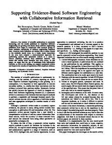
Example Design Point To ground our system design study, we have developed a small, flexible networked
sensor platform that expresses many of the key characteristics of the general class and represents the various internal interfaces using currently available components [38]. A photograph and schematic for the hardware configuration of this device appear in Figure 1. It consists of a microcontroller with internal flash program memory, data SRAM and data EEPROM, connected to a set of actuator and sensor devices, including LEDs, a low-power radio transceiver, an analog photo-sensor, a digital temperature sensor, a serial port, and a small coprocessor unit. This prototype has been invaluable in developing a feel for the salient issues in this design regime.
3.1
Hardware Organization The processor within the MCU (ATMEL 90LS8535) [2], which conventionally re-
ceives so much attention, is not particularly noteworthy. It is an 8-bit Harvard architecture
6 with 16-bit addresses. It provides 32 8-bit general registers and runs at 4 MHz and 3.0 volts. The system is very memory constrained: it has 8 KB of flash as the program memory, and 512 bytes of SRAM as the data memory. The MCU is designed such that a processor cannot write to instruction memory; our prototype uses a coprocessor to perform that function. Additionally, the processor integrates a set of timers and counters which can be configured to generate interrupts at regular time intervals. More noteworthy are the three sleep modes: idle, which just shuts off the processor, power down, which shuts off everything but the watchdog and asynchronous interrupt logic necessary for wake up, and power save, which is similar to the power down mode, but leaves an asynchronous timer running. Finally, it also contains an internal analog to digital converter for reading analog sensor inputs. Three LEDs represent analog outputs connected through a general I/O port; they may be used to display digital values or status. The photo-sensor represents an analog input device with simple control lines. In this case, the control lines eliminate power drain through the photo resistor when not in use. The input signal can be directed to the internal analog to digital converter in continuous or sampled modes. The radio is the most important component. It represents an asynchronous input/output device with hard real time constraints. It consists of an RF Monolithics 916.50 MHz transceiver (TR1000) [10], antenna, and collection of discrete components to configure the physical layer characteristics such as signal strength and sensitivity. It operates in an ON-OFF key mode at speeds up to 19.2 Kbps. Control signals configure the radio to operate in either transmit, receive, or power-off mode. The radio contains no buffering so each bit must be serviced by the controller on time. Additionally, the transmitted value is not latched by the radio, so jitter at the radio input is propagated into the transmission signal. The temperature sensor (Analog Devices AD7418) represents a large class of digital sensors which have internal A/D converters and interface over a standard chip-to-chip
7 protocol. In this case, the synchronous, two-wire I2 C [48] protocol is used with software on the microcontroller synthesizing the I2 C master over general I/O pins. In general, up to eight different I2 C devices can be attached to this serial bus, each with a unique ID. The protocol is rather different from conventional bus protocols, as there is no explicit arbiter. Bus negotiations must be carried out by software on the microcontroller. The serial port represents an important asynchronous bit-level device with bytelevel controller support. It uses I/O pins that are connected to an internal UART controller. In transmit mode, the UART takes a byte of data and shifts it out serially at a specified interval. In receive mode, it samples the input pin for a transition and shifts in bits at a specified interval from the edge. Interrupts are triggered in the processor to signal completion events. The coprocessor represents a synchronous bit-level device with byte-level support. In this case, it is a very limited MCU (AT90LS2343 [2], with 2 KB flash instruction memory, 128 bytes of SRAM and EEPROM) that uses I/O pins connected to an SPI controller. SPI is a synchronous serial data link, providing high speed full-duplex connections (up to 1 Mbit) between various peripherals. The coprocessor is connected in a way that allows it to reprogram the main microcontroller. The sensor can be reprogrammed by transferring data from the network into the coprocessor’s 256 KB EEPROM (24LC256). Alternatively the main processor can use the coprocessor as a gateway to extra storage. Future extensions to the design will include the addition of battery strength monitoring via voltage and temperature measurements, radio signal strength sensor, radio transmission strength actuator, and a general I2 C sensor extension bus.
3.2
Power Characteristics Table 1 shows the current drawn by each hardware component under three sce-
narios: peak load when active, load in “idle” mode, and inactive. When active, the power
8
AT 90LS8535 8bit data bus
I2C
SRAM
SPI
SPI
Coprocessor AT90L2313
TX RX
Serial Port
EEPROM
PC
UART Pgm. mem. (flash)
IO pins ADC
Inst. Register
IO pins Inst. Decoder Ctrl lines
data I2C
Light Sensor Temp AD7418
Ctrl
IO pins
Regs
TX RX
RFM TR100 916 MHz transceiver
Int unit
ALU SR
Timer Unit
SP
IO pins
EEPROM
Reference Voltage
Pwr
4 MHz clock
LEDs
32.768 MHz clock
Figure 1: Photograph and schematic for representative network sensor platform
9 Component MCU core (AT90S8535) MCU pins LED Photocell Radio (RFM TR1000) Temp (AD7416) Co-proc (AT90LS2343) EEPROM (24LC256)
Active (mA) 5 1.5 4.6 each .3 12 tx, 4.5 rcv 1 2.4 3
Idle (mA) 2 0.6 .5 -
Inactive (µ A) 1 5 1.5 1 1
Table 1: Current draw per hardware component of baseline networked sensor platform.
consumption of the LED and radio reception are about equal to the processor. The processor, radio, and sensors running at peak load consume 19.5 mA at 3 volts, or about 60 mW. (If all the LEDs are on, this increases to 100 mW.) This figure should be contrasted with the 10 µA current draw in the inactive mode. Clearly, the biggest savings are obtained by making unused components inactive whenever possible. The system must embrace the philosophy of getting the work done as quickly as possible and going to sleep. Our prototype is powered by an Energizer CR2450 lithium battery rated at 575 mAh [32]. At peak load, the system can run about 30 hours on a single battery. In the idle mode, the system can run for 200 hours. When switched into inactive mode, the system draws only 10 µA of current, and a single battery can run for over a year. The minimum pulse width for the RFM radio is 52 µs. Thus, it takes 1.9 µJ of energy to transmit a single bit of one. Transmitting a zero is free, so at equal DC balance (which is roughly what the transmitter requires for proper operation), it costs about a 1 µJ to transmit a bit and 0.5 µJ to receive a bit. During this time, the processor can execute 208 cycles (roughly 100 instructions) and can consume up to .8 µJ. A fraction of this instruction count is devoted to bit level processing. The remainder can go to higher level processing (byte-level, packet level, application level) amortized over several bit times. Unused time can be spent in idle or power-down mode. To broaden the coverage of our study, we deploy these networked sensors in two
10 configurations. One is a mobile sensor that picks up temperature and light readings and periodically presents them on the wireless network as tagged data objects. It needs to conserve its limited energy. The second is a stationary sensor that bridges the radio network through the serial link to a host on the Internet. It has power supplied by its host, but also has more demanding data flows. These devices are significantly different than traditional mobile computing devices. The primary difference is that there is no user interface. Traditional devices such as Palm Pilots and other PDA’s are optimized for user response times, while our device is intended to go unnoticed. PDA’s are designed for quick periods of high activity and long periods of idle time. On the contrary, our device must be capable of long periods of constant data collection. The peak power consumption of the CPU in a Palm Pilot is an order of magnitude greater than ours. This low power consumption allows us to target long term sensor deployments.
4
Tiny Microthreading Operating System (TinyOS) The core challenge we face is to meet the requirements for networked sensors put
forth in Section 2 upon the class of platforms represented by the design in Section 3 in a manner that scales forward to future technology. Small physical size, modest active power load and tiny inactive load are provided by the hardware design. An operating system framework is needed that will retain these characteristics by managing the hardware capabilities effectively, while supporting concurrency-intensive operation in a manner that achieves efficient modularity and robustness. For reasons described in Section 10, existing embedded device operating systems do not meet this challenge. Also, we desire a clean open platform to explore alternatives. The problem we must tackle is strikingly similar to that of building efficient network interfaces, which also must maintain a large number of concurrent flows and juggle numerous
11 outstanding events [20]. This has been tackled through physical parallelism [21] and virtual machines [29]. We tackle it by building an extremely efficient multithreading engine. As in TAM [22] and CILK [24] it maintains a two-level scheduling structure, so a small amount of processing associated with hardware events can be performed immediately while long running tasks are interrupted. The execution model is similar to FSM models, but considerably more programmable. Our system is designed to scale with the current technology trends supporting both smaller, tightly integrated designs as well as the crossover of software components into hardware. This is in contrast to traditional notions of scalability that are centered on scaling up total power/resources/ work for a given computing paradigm. It is essential that network sensor architectures plan for the eventual integration of sensors, processing and communication. The days of sensor packs being dominated by interconnect and support hardware, as opposed to physical sensors, are numbered. In TinyOS, we have chosen an event model so that high levels of concurrency can be handled in a very small amount of space. A stack-based threaded approach would require that stack space be reserved for each execution context. Additionally, in order to service the 19,200 bps radio on a bit-by-bit basis, it would need to be able to multi-task between these execution contexts at a rate of 40,000 switches per second. This is twice every 50 µs, once to service the radio and once to perform all other work. It is clear that an event-based regime lends itself to these requirements. It is not surprising that researchers in the area of high performance computing have seen this same phenomena – that event based programming must be used to achieve high performance in concurrency intensive applications [30, 50]. In this design space, power is the most precious resource. We believe that the event-based approach creates a system that uses CPU resources efficiently. The collection of tasks associated with an event are handled rapidly, and no blocking or polling is permitted. Unused CPU cycles are spent in the sleep state as opposed to actively looking for
12 an interesting event. Additionally, with real-time constraints the calculation of CPU utilization becomes simple – allowing for algorithms that adjust processor speed and voltage accordingly [43, 53].
4.1
TinyOS Design TinyOS is divided into a collection of software components. A complete system
configuration consists of a tiny scheduler and a graph of these components. A component has four interrelated parts: a set of command handlers, a set of event handlers, an encapsulated fixed-size frame, and a bundle of simple tasks. Tasks, commands, and handlers execute in the context of the frame and operate on its state. To facilitate modularity, each component also declares the commands it uses and the events it signals. These declarations are used to compose the modular components in a per-application configuration. The composition process creates layers of components where higher level components issue commands to lower level components and lower level components signal events to the higher level components. Physical hardware represents the lowest level of components. The fixed size frames are statically allocated which allows us to know the memory requirements of a component at compile time. Additionally, it prevents the overhead associated with dynamic allocation. This savings manifests itself in many ways, including execution time savings because variable locations can be statically compiled into the program instead of accessing state via pointers. Commands are non-blocking requests made to lower level components. Typically, a command will deposit request parameters into its frame and conditionally post a task for later execution. It may also invoke commands on lower level components. However, it must not wait for long latency actions to take place. A command must provide feedback to its caller by returning status indicating whether it was successful or not, e.g., buffer overrun. Event handlers are invoked to deal with hardware events, either directly or indi-
13 rectly. The lowest level components have handlers connected directly to hardware interrupts, which may be external interrupts, timer events, or counter events. An event handler can deposit information into its frame, post tasks, signal higher level events or call lower level commands. A hardware event triggers a fountain of processing that goes upward through events and can bend downward through commands. In order to avoid cycles in the command/event chain, commands cannot signal events. Both commands and events are intended to perform a small, fixed amount of work, which occurs within the context of their component’s state. Tasks perform the primary work. They are atomic with respect to other tasks and run to completion, though they can be preempted by events. Tasks can call lower level commands, signal higher level events, and schedule other tasks within a component. The run-to-completion semantics of tasks make it possible to allocate a single stack that is assigned to the currently executing task. This is essential in memory constrained systems. Tasks allow us to simulate concurrency within each component, since they execute asynchronously with respect to events. However, tasks must never block or spin wait or they will prevent progress in other components. While events and commands approximate instantaneous state transitions, task bundles provide a way to incorporate arbitrary computation into the event driven model. The task scheduler is currently a simple FIFO scheduler, utilizing a bounded size scheduling data structure. Depending on the requirements of the application, more sophisticated priority-based or deadline-based structures can be used. It is crucial that the scheduler is power aware: our prototype puts the processor to sleep when the task queue is empty, but leaves the peripherals operating, so that any of them can wake up the system. This behavior enables us to provide efficient battery usage (see Section 8). Once the queue is empty, another task can be scheduled only as a result of an event, thus there is no need for the scheduler to wake up until a hardware event triggers activity. More aggressive power
14 management is left to the application.
4.2
Example Component A typical component including a frame, event handlers, commands and tasks for
a message handling component is pictured in Figure 2. Like most components, it exports commands for initialization and power management. Additionally, it has a command for initiating a message transmission, and signals events on the completion of a transmission or the arrival of a message. In order to perform its function, the messaging component issues commands to a packet level component and handles two types of events: one that indicates a message has been transmitted and one that signals that a message has been received. Pictorially, we represent the component as a bundle of tasks, a block of state (component frame) a set of commands (upside-down triangles), a set of handlers (triangles), solid downward arcs for commands they use, and dashed upward arcs for events they signal. Figure 3 shows how all of these elements are explicit in the component code. Since the components describe both the resources they provide and the resources they require, connecting them together is very simple. The programmer simply matches the signatures of events and commands required by one component with the signatures of events and commands provided by another component. The communication across the components takes the form of a function call, which has low overhead and provides compile time type checking.
4.3
Component Types In general, components fall into one of three categories: hardware abstractions,
synthetic hardware, and high level software components. Hardware abstraction components map physical hardware into our component model. Our RFM radio component is representative of this class. It exports commands
msg_send_done(success)
msg_rec(type, data)
send_msg (addr,type,data)
power(mode)
init
15
send_msg_thread
internal state
RX_packet_done (buffer)
TX_packet_done (success)
TX_packet(buf)
power(mode)
init
Messaging Component
Figure 2: Graphical representation of sample messaging component.
ACCEPTS{ char AM_SEND_MSG(char addr,char type, char* data); char AM_POWER(char mode); char AM_INIT(); };
SIGNALS{ char char } HANDLES{ char char };
AM_MSG_SEND_DONE(char success); AM_MSG_REC(char* data);
AM_TX_PACKET_DONE(char success); AM_RX_PACKET_DONE(char* packet);
USES{ char AM_SUB_TX_PACKET(char* data); void AM_SUB_POWER(char mode); char AM_SUB_INIT(); };
Figure 3: Declaration of sample messaging component.
16 to manipulate the individual I/O pins connected to the RFM transceiver and posts events informing other components about the transmission and reception of bits. Its frame contains information about the current state of the component (the transceiver is in sending or receiving mode, the current bit rate, etc.). The RFM consumes the hardware interrupt, which is transformed into either the RX bit evt or into the TX bit evt. There are no tasks within the RFM because the hardware itself provides the concurrency. This model of abstracting over the hardware resources can scale from very simple resources, like individual I/O pins, to quite complex ones, like UARTs. Synthetic hardware components simulate the behavior of advanced hardware. A good example of such component is the Radio Byte component (see Figure 8). It shifts data into or out of the underlying RFM module and signals when an entire byte has completed. The internal tasks perform simple encoding and decoding of the data.
1
Con-
ceptually, this component is an enhanced state machine that could be directly cast into hardware. From the point of view of the higher levels, this component provides an interface and functionality very similar to the UART hardware abstraction component: they provide the same commands and signal the same events, deal with data of the same granularity, and internally perform similar tasks (looking for a start bit or symbol, perform simple encoding, etc.). The high level software components perform control, routing and all data transformations. A representative of this class is the messaging module presented above, in Figure 2. It performs the function of filling in a packet buffer prior to transmission and dispatches received messages to their appropriate place. Additionally, components that perform calculations on data or data aggregation fall into this category. Our component model allows for easy migration of the hardware/software boundary. This is possible because our event based model is complementary to the underlying 1
The radio requires that the data transmitted is DC-balanced. We currently use Manchester encoding.
17 hardware. Additionally, the use of fixed size, preallocated storage is a requirement for hardware based implementations. This ease of migration from software to hardware will be particularly important for networked sensors, where the system designers will want to explore the tradeoffs between the scale of integration, power requirements, and the cost of the system.
4.4
Component Composition In order to support the modular nature of TinyOS, we have developed a set of
tools that assist the developer to link components together. In TinyOS, components are linked together at compile time which allows us to eliminate unnecessary runtime overhead. To facilitate composition, each component’s external interface is described with a .comp file. In these files, each component lists the set of commands it accepts and the events it handles as well as the set of events it signals and the commands it uses. Logically we view each of the inputs and outputs of a component as an I/O pin as if the component were a physical piece of hardware. This complete description of a component’s upper and lower interface is used by our compile time tools to automatically generate component header files. Figure 4 contains an example .comp file for a simple application that blinks the LEDs. In order to actually compose individual components into a complete application, TinyOS uses description (.desc) files. These files contain the listing of components to be used as well as the logical connections between the components. The description file can be thought of as a parts lists and a wiring diagram. These description files are divided into two sections. The first section directly lists the modules to include in the application. The second section of the file lists the connections between the component’s I/O pins. This wiring diagram takes the form of lists of pins that are logically connected. Each line of the file contains a set of inputs and outputs in the form COMPONENT:FUNCTION which are to be connected together with a wiring network. Figure 5 contains and example description
18 TOS_MODULE BLINK; ACCEPTS{ char BLINK_INIT(); }; HANDLES{ void BLINK_CLOCK_EVENT(); }; USES{ char char char char char char char
BLINK_SUB_INIT(char interval); BLINK_LEDy_on(); BLINK_LEDy_off(); BLINK_LEDr_on(); BLINK_LEDr_off(); BLINK_LEDg_on(); BLINK_LEDg_off();
}; SIGNALS{ };
Figure 4: An example comp file, BLINK.comp
file for a simple application. At compile time, the component descriptions (.comp) files and the application description (.desc) files are preprocessed in order to create a header file that links the components together. Just as in hardware, a net in our system can have multiple sources and sinks. This is automatically handled by our compilation tools. For example, a single event can be handled by multiple components by simply connecting multiple components that handle the event together. At compile time, code will be automatically generated to send the event as many places as necessary.
19 include modules{ MAIN; BLINK; CLOCK; LEDS; }; BLINK:BLINK_INIT MAIN:MAIN_SUB_INIT BLINK:BLINK_APP_DONE MAIN:MAIN_SUB_SEND_DONE BLINK:BLINK_LEDy_on LEDS:YELLOW_LED_ON BLINK:BLINK_LEDy_off LEDS:YELLOW_LED_OFF BLINK:BLINK_LEDr_on LEDS:RED_LED_ON BLINK:BLINK_LEDr_off LEDS:RED_LED_OFF BLINK:BLINK_LEDg_on LEDS:GREEN_LED_ON BLINK:BLINK_LEDg_off LEDS:GREEN_LED_OFF BLINK:BLINK_SUB_INIT CLOCK:CLOCK_INIT BLINK:BLINK_CLOCK_EVENT CLOCK:CLOCK_FIRE_EVENT
Figure 5: An example description file, blink.desc
4.5
Application Walk Through In order to show what applications look like in TinyOS, we’ll walk through a simple
application that is included in the TinyOS release. The application, BLINK, simply turns on and off the LEDs of the system in a binary counting fashion. While this application could easily be written without the help of the TinyOS models, it demonstrates some of the core concepts in TinyOS. As described in section 4.4, components must declare their external interface. This declaration is the starting point for application development. Figure 4 shows the .comp file for the BLINK application. The application accepts a single command, BLINK INIT, and handles a single event, BLINK CLOCK EVENT. Additionally, it uses several commands of other components. This interface file completely describes what functionality needs to be provided by other parts of the system for this component to function correctly. In particular, this component needs to be initialized, it needs to have a clock event, and it needs to have
20 a place to issue LED on and off commands. The actual code can then be written to fill in this interface. Figure 6 contains the source code of the actual application. There are three major sections of the blink application. The first is the declaration of the component’s frame. To declare a frame, the application developer must declare the frame type and then use the TinyOS macros to declare the contents of the frame. Essentially, the frame is a specialized C Structure that is statically allocated and accessible only to the component. In this case, the application has a single variable in the frame called state. This variable contains the current value of the binary counter being displayed on the LEDs. The second section of the code contains an initialization function. This function performs all of the necessary initialization for this component. Additionally, this function must initialize all sub-components that are used. In this example, the BLINK INIT function issues three commands to turn all of the LEDs off, and sends an initialization command down to the CLOCK component. These commands must be issued with the use of the TOS CALL COMMAND macro. The final section of the application is the clock event handler. This function is automatically invoked when a clock event is signaled. This application uses this event to change the state of the LEDs and the binary counter. When the application is running, the clock component will periodically invoke this function. In this case, when the function is invoked the state variable is incremented, thus increasing the value of the binary counter. This state variable is also truncated to three bits corresponding to the three LEDs. Note that the state variable in the component’s frame is accessed via the VAR macro. This macro automatically accesses a component’s frame as opposed to the locally allocated stack variables. In this case, a temporary variable named state is also present. However, only the variable accesses that use the VAR macro go to the frame. Once the value of the counter is computed, it is then displayed on the LEDs by a series of commands to the LED component. The event handler then returns.
21
#include "tos.h" #include "BLINK.h" //Frame Declaration #define TOS_FRAME_TYPE BLINK_frame TOS_FRAME_BEGIN(BLINK_frame) { char state; } TOS_FRAME_END(BLINK_frame); ============================================================ /* Accepts INIT Command from above*/ /* BLINK_INIT*/ char TOS_COMMAND(BLINK_INIT)(){ TOS_CALL_COMMAND(BLINK_LEDy_off)(); TOS_CALL_COMMAND(BLINK_LEDr_off)(); TOS_CALL_COMMAND(BLINK_LEDg_off)(); TOS_CALL_COMMAND(BLINK_SUB_INIT)(0x03); /* initialize clock component */ return 1; } ============================================================ /* Clock Event Handler: update LED state as 3-bit counter and set LEDs to match */ void TOS_EVENT(BLINK_CLOCK_EVENT)(){ char state = VAR(state) = (VAR(state)+1) & 7; if (state & 1) TOS_CALL_COMMAND(BLINK_LEDy_on)(); else TOS_CALL_COMMAND(BLINK_LEDy_off)(); if (state & 2) TOS_CALL_COMMAND(BLINK_LEDg_on)(); else TOS_CALL_COMMAND(BLINK_LEDg_off)(); if (state & 4) TOS_CALL_COMMAND(BLINK_LEDr_on)(); else TOS_CALL_COMMAND(BLINK_LEDr_off)(); }
Figure 6: An example application level component, blink.c
22 Note that the application never holds on to an execution context. Both the initialization routine and the event handler release the execution context quickly. This is an essential property of a TinyOS application. By not holding onto an execution context, a single context can be shared across multiple applications. If this application were to be implemented in a threaded execution model, as opposed to the event based TinyOS model, this simple application would require a dedicated execution context. It would block until it was time to update the counter. This would consume a significant amount of resources while idle. In contrast, this application simply consumes a single byte of memory while idle. In addition to writing the individual application level components, the application developer must also assemble a collection of TinyOS components into a complete application. As described in section 4.4, an application description file must be written that logically connects each of the individual components. Figure 5 shows the description file for this application. The first section of the file contains the list of components that need to be included. In this case, the complete application consists of the MAIN component, the BLINK component, the CLOCK component and the LEDS component. The second section of the file then contains the connections between the components. The first line of this section states that the BLINK component’s BLINK INIT command is connected to the MAIN component’s MAIN SUB INIT command. Our current implementation of TinyOS contains a simple runtime environment that places significant limitations as to what actions can be performed in a command and event handler. In particular, commands and events cannot perform long running computation. This allows the single execution context to be shared across multiple components while permitting components to be capable of meeting real time requirements. In order to allow arbitrary computation, a component must schedule a task to run. Tasks run at a low priority and can be interrupted by higher priority events. It is clear that as devices become more complex, different TinyOS runtimes will be possible. For example, queues can
23 be placed between components to buffer commands and events instead of having them be passed as function calls. TinyOS is built so that modifications of this nature can be made without modifications to application code.
5
Network Sensor Communication Paradigms A key piece of TinyOS is its communication model. Instead of scaling PC based
communication models down, we believe that it is beneficial to tailor the communication system to meet the needs of these devices. To accomplish this, we have used the Active Messages communication model and the event based TinyOS as building blocks for our solution.
5.1
Active Messages Active Messages (AM) is a simple, extensible paradigm for message-based commu-
nication widely used in parallel and distributed computing systems [37, 51]. Each Active Message contains the name of a user-level handler to be invoked on a target node upon arrival and a data payload to pass in as arguments. The handler function serves the dual purpose of extracting the message from the network and either integrating the data into the computation or sending a response message. The network is modeled as a pipeline with minimal buffering for messages. This eliminates many of the buffering difficulties faced by communication schemes that use blocking protocols or special send/receive buffers. To prevent network congestion and ensure adequate performance, message handlers must be able to execute quickly and asynchronously. Although Active Messages has its roots in large parallel processing machines and computing clusters, the same basic concepts can be used to the meet the constraints of networked sensors. Specifically, the lightweight architecture of Active Messages can be leveraged to balance the need for an extensible communication framework while maintaining
24 efficiency and agility. More importantly, the event based handler invocation model allows application developers to avoid busy-waiting for data to arrive and allows the system to overlap communication with other activities such as interacting with sensors or executing other applications. It is this event centric nature of Active Messages which makes it a natural fit for these devices.
5.2
Tiny Active Messages In bringing Active Messages out of the high performance parallel computing world
and down into this low power design regime, we have attempted to preserve the basic concepts of integrating communication with computation and matching communication primitives to hardware capabilities. The basic paradigm of typed messages causing handlers to be invoked upon arrival matches up well with the event based programming model supported by TinyOS and demanded by the underlying sensor hardware. The low overhead associated with event based notification is complementary to the limited resources of networked sensors. Applications do not need to waste resources while waiting for messages to arrive. Additionally, the overlap of computational work with application level communication is essential. Execution contexts and stack space must never be wasted because applications are blocked, waiting for communication. Essentially, the Active Messages communication model can be viewed as a distributed event model where networked nodes send each other events. While quite basic, we believe that all applications can be built on top of this primitive model. In order to make the Active Messages communication model a reality, certain primitives must be provided by the system. We believe that the three basic primitives are: best effort message transmission, addressing, and dispatch. More demanding applications may need to build more functionality on top of these primitives, but that is left for the application developer to decide. By creating the minimal kernel of a communication system,
25 all applications will be able to build on top of it. Additionally, it is likely that there will be a large variety of devices with different physical communication capabilities and needs. By building the communication kernel as three separate components in the TinyOS component model, developers can pick and choose which implementations of the basic components they need. This can take the form of selecting from a collection of delivery components that perform different levels of error correction and detection. However, by providing a consistent interface to communication primitives, application developers can easily transfer their applications to different hardware platforms. Just as there will be various implementations of the core components for the developer to choose from, various other extensions will be available such as reliable delivery. This is similar to the design of Horus [47], which attempted to have modular PC based communication protocols where application developers could chose from a variety of building blocks including encryption, flow control, and packet fragmentation. It is extremely advantageous to be able to customize protocols when dealing with Networked Sensors due to their extreme performance constraints and their large diversity of physical hardware. Finally, the selection of an event based communication mechanism does not preclude the use of a threaded, blocking, execution model. An event-based model can easily be transformed into a threaded model through the use of a queue, where an event simply places the data into a queue structure that can be accessed by the thread. When the queue is empty, the thread can block until data arrives. On the contrary, it is difficult to switch from a threaded implementation to an event-based model. Similarly, the immediate propagation of messages to the application layer does not prevent the use of buffers to temporarily hold messages until the application is ready to deal with them. An application level buffer component could be used to accomplish this. However, including extra buffers inside the communication primitives precludes the application from eliminating them.
26
5.3
Implementation In this section, we present the design of our Tiny Active Messages implementation.
We believe that the basic primitives that we have provided are all that is needed to construct application level protocols that meet any application’s needs. The discussion includes the device and host PC components and aspects that are common to both. We will follow with an evaluation section that demonstrates how we have successfully used these primitives to construct an ad-hoc networking application based on data collection using networked sensors.
Components The interface to our messaging component is quite simple. It accepts TinyOS commands from the applications to initiate message transfers and fires off events to message handlers based on the type of messages that have been received. There is an additional event that signals the completion of a transmission. Send commands include the destination address, handler ID, and message body. Internally, our Active Messages component performs address checking and dispatch, and relies on sub components for basic packet transmission. Figure 8 shows the complete TinyOS component graph of an application that uses the Active Messages communication model. The underlying packet level processing components simply perform the function of transmitting the block of bytes out over the radio. We assume that this is a best effort transmission mechanism. While we do not expect reliable, error free delivery, we do assume that there will be some basic logic that attempts to avoid transmission collisions. The interface to the packet level component provides a mechanism to initiate the transmission of a fixed size, 30 byte packet, as well as events that are fired when a transmission or a reception is complete. We have multiple implementations of packet level components each providing different levels of error correction or detection. These include, basic transmission
27 without any error detection or correction, CRC checked packets that have error detection, and forward error corrected packets that provide basic error correction as well as error detection. Additionally, we have implemented a Host PC package that consists of a software library that is linked into applications. The library communicates over the PC serial port to a special base station sensor that has both a RS232 communication channel as well as RF communication. This provides a way to quickly develop communication bridges that bring data collected and transmitted on the networked sensors into a more traditional computing environment. Using this library, it is simple to create a bridge that retransmits messages collected from the networked sensors onto the Internet using TCP/IP or UDP.
Packet Format The first two bytes of a received packet are used to identify the destination of the packet (R0 ) and the ID of the message handler that is to be invoked on the packet (H0 ). The AM component first checks that the address matches the local address and then it invokes the listed handler, passing on the remaining 28 bytes of the packet. In the event that the message is bound for a handler that is not present on the receiving device, the packet is ignored. The dispatch routine that is used by the message handler is automatically generated at compile time based on the message handlers that are present. This is done to eliminate the need for expensive handler registration mechanisms.
Multi-hop Packet Format In order to demonstrate how application specific needs could be met by building on top of the basic Active Messages primitives, we have developed a component that supports source based multi-hop routing. To accomplish this, we have defined a generic message format and specialized routing handler. This format, depicted in Figure 7, dedicates seven
28
R0 H0 N Hf R1 R2 R3 R4 S D0 D1
...
R0 - Next Hop H0 - Next Handler N - Number of Hops H0 - Destination Handler R1, R2 ,R3 ,R4 - Route Hops S - Sending Node D0, D1 … - Payload
Figure 7: Multi-hop packet format.
additional bytes to allow a maximum of 4-hop communication. Four of these bytes are used to hold the intermediate hops of the route (R1 ,R2 ,R3 ,R4 ): one is used for the number of hops left (N ), one is used to store the source of the packet (S), and one is used for the handler ID that is to be invoked once the message arrives at its destination (HF ). In this instance, the multi-hop router is simply the handler of a typed message. More complex routing information is stored inside the message and used by application level handlers to route the packet to its next destination. This simple component can be used in any application that wishes to have source based routing. Additionally, applications that need other functionality can seamlessly coexist. While the packet is in-route, H0 is set to zero (the routing handler). In response to the reception of a packet, the routing handler decrements the hop count and rotates in the next hop and pushes the local node address to the end of the route chain. This process records the route that the packet has taken in the route table so that the recipient knows how to route a response packet. If the next hop is the final destination (number of hops is one), the routing handler inserts the destination handler, HF , into H0 .
Special Addresses In developing sample applications to test the usability of our messaging layer, two special addresses were defined. The first special address needed was the broadcast address
29 (0xff). The concept of a one-to-all broadcast greatly simplifies the route discovery and exploration algorithms. Combining this with routing handlers designed to record the path that a packet has taken yields a trivial implementation of a route discovery application. In its simplest form, an application can send a two-hop packet to the broadcast address followed by its own address. This will cause any device that is in range to respond with its own address recorded in the packet that the original device receives. Secondly, a special address was chosen for the Host PC in the device virtual network. Arbitrarily chosen to be 0x7e, a device receiving a packet for this destination forwards the packet to the local data UART instead of the radio. This exposes the basic need to have the notion of gateway addresses that get treated specially.
Rules for Usage In TinyOS, multiple applications will hare a single messaging layer. It is important to understand the potential interactions of these applications. Additionally, a single application could have multiple simultaneous message transmissions that interact unexpectedly. The Active Messages layer can only handle a single message at a time. If a message transmission is in progress, a request to transmit an additional message will be denied. An application must then retry transmission at a later time. An easy way to schedule the retry is to have it triggered by the send done event that is signaled when the current transmission is completed. In many data collection applications, it may be better to simply throw away the message and wait to transmit the next sensor readings. If this is done, it is important to ensure that transmissions will not always collide. This would be the case if two applications were listening to the same event and using it to trigger a message transmission. Every time the event occurred, one of the applications would get its message out and one would fail. Because of how TinyOS dispatches events to multiple places, the same application
30 transmission would succeed each time. In addition to only being able to transmit a single message at a time, the Active Messages layer cannot receive a message while a transmission is in progress. Once a message transmission begins, it runs to completion. This is a direct result of having a half duplex radio. Applications can also interact unexpectedly if developers are unaware of the correct way to use message buffers. Because TinyOS has a highly constrained memory model, applications must make efficient use of message buffers. A handful of message buffers will be continually reused. Particularly, it is important to know when an application can reuse a send buffer, and to know how long a message remains in a receive buffer. When an application sends out a message, it provides the Active Messages layer with a pointer to a memory buffer. The data in this buffer must remain unchanged until the transmission is complete. This means that the application cannot modify the buffer until the Active Messages layer has fired the send done event. When an application receives an incoming message, the messaging layer provides a pointer to the buffer where the message is stored. This data is only guaranteed to be valid for the duration the event that delivered the message. If the application needs to keep the data longer, it must copy the data elsewhere. Once the event handler returns, the messaging layer will receive subsequent messages into the same buffer. This will overwrite the original message. In our multi-hop routing application, messages will be received, modified, and retransmitted to the next recipient. In this case, we will not want to create a complete copy of the message. In our code, we simply pass the receive buffer back to the messaging layer as a transmission buffer. This is valid because once the message transmission begins, no message reception can occur. Because the buffer will remain unmodified until a message is received into it, the buffer will remain unmodified until the transmission completes. This
31 means that the buffer will not be overwritten by other incoming messages. One shortcoming of this buffer usage model is that it is difficult for an application to receive several messages before processing the data. Currently, the application needs to copy each message into a private buffer. An alternative mechanism that could be used would be to allow the application to return a different buffer to the messaging layer when a message is received. The application would be allowed to trade buffers with messaging layer. This same extension could be applied to the management of transmission buffers as well.
6
A Complete Application We have built an ad hoc networking application to collect information from a set of
nodes that have been randomly distributed throughout the environment. They monitor the temperature and light conditions and periodically transmit their measurements to a base station. The application uses the Active Message primitives to explore routing topology and then to propagate information toward a central collection node. Additionally, as sensors are relocated the application automatically reconfigures itself in light of the new routing topology. We have selected this application because we believe that this closely mirrors real world networked sensor applications. The internal component graph of a base station sensor is shown in Figure 8 along with the routing topology created by a collection of sensors. The source code for the ad hoc routing component is included in the appendix. To construct our ad-hoc network we use a variation on a Destination-Sequenced Distance Vector [44] algorithm tailored to having all nodes transmit to a base station. While not the most efficient algorithm, it is straightforward to implement and understand. It serves the purpose of demonstrating the capabilities of our system. Our framework can easily be used to implement and evaluate more sophisticated networking algorithms. In our system, each node has a unique identity and the base station knows that
32
Ad hoc Routing Application application
Active Messages
packet Radio Packet
Serial Packet
Temperature SW
byte HW Radio Byte
UART
I2C
Photo
bit RFM
Clocks
Figure 8: A sample configuration of a networked sensor and the routing topology created by a collection of distributed sensors.
33 it is directly connected to the host PC. Each node then attempts to determine the id of a parent who is one hop closer to the base station. This collection of nodes that have each selected a parent forms a tree that is rooted at the base station. Each node tries to be as close to the base station as possible so that its messages reach the base station in as few hops as possible. In order to determine this tree structure, each node broadcasts its depth in the tree. These broadcasts are essentially advertisements. Each node selects the node that is advertising the lowest depth as its parent. The node then sets its depth as one more than its parent and sends out an advertisement. At first, only the base station can send out these advertisements because it is the only node that knows its depth. All nodes in range of the base station hear this advertisement and learn that they are one hop from the base station. Eventually all nodes learn their depth. While the network as a whole has determined the routing topology, each node simply knows, and needs to remember, its parent. In order to handle network reorganization, we introduce the notion of expiration. Time is divided into eras, and each node remembers the identity of the best advertisement it hears in an era. The eras are determined by the base station. Era boundaries occur when the base station sends out its advertisement. Each node re-advertises in response to hearing a parent’s advertisement. This causes each node to hear the best advertisements first because the higher level advertisements trigger the lower level advertisements. For each node, the first advertisement heard signals that a new era has begun. The advertisements serve the dual purpose of time synchronization and routing updates. To collect information from the network, each node periodically transmits its sensor readings to its parent. As data travels towards the base station, the identities of the intermediate hops are added to the packet. This allows us to record the overall routing topology that the network is using. By looking at the routes traveled by several packets from different sources, we can eventually determine the topology of the entire system.
34 For demonstration purposes, we feed this information into a display application that plots the current routing topology graphically. This takes the form of a tree rooted at the base station node with edges corresponding to communication routes. One example is shown in Figure 8. Each node is labeled with the ID of the device and decorated with a box that represents light level sensor reading being collected. Information is also displayed showing the number of data packets that have traveled through a node and received from a node. In this application, there are three I/O devices that must be serviced: the network, the light sensor, and the temperature sensor. In the TinyOS component model, each of these devices is represented by a vertical stack of components. The stacks are tied together by the application layer. Internally, when our application is running, thousands of events are flowing through each sensor. A timer event is used to periodically start the data collection. Once the temperature and light information have been collected, the application uses the messaging layer’s send message command to initiate a transfer. This command records the message location in the AM component’s frame and schedules a task to handle the transmission. When executed, this task composes a packet, and initiates a downward chain of commands by calling the TX packet command in the Packet component. In turn, the command calls TX byte within the Radio Byte component to start the byte-by-byte transmission. The Packet component internally acts as a data drain, handing bytes down to the Radio Byte component whenever the previous byte transmission is complete. The Radio Byte prepares for transmission by putting the RFM component into the transmission state (if appropriate) and scheduling the encode task to prepare the byte for transmission. When the encode task is scheduled, it encodes the data, and sends the first bit of data to the RFM component for transmission. The Radio Byte also acts as a data drain, providing bits to the RFM in response to the TX bit evt event. If the byte transmission is complete, then
35 the Radio Byte will propagate the TX bit evt signal to the packet-level controller through the TX byte done event. When all the bytes of the packet have been drained, the packet level will signal the TX packet done event, which will signal the the application through the msg send done event. When a transmission is not in progress, and the sensor is active, the Radio Byte component receives bits from the RFM component. If the start sequence is detected, the transmission process is reversed: bits are collected into bytes and bytes are collected into packets. Each component acts as a data-pump: it actively signals the incoming data to the higher levels of the system, rather than respond to a read operation from above. Once a packet is available, the address of the packet is checked and if it matches the local address the appropriate handler is invoked.
7
Components Contained in TinyOS There are several system level components that are included in TinyOS. Addi-
tionally, there are a collection of example applications that demonstrate the usages of the TinyOS system. Table 10 contains a listing of the components contained in the current TinyOS release.
8
Evaluation We will first evaluate the TinyOS software for networked sensors with respect to
the set of requirements outlined in section 2. Secondly, we will evaluate the Active Messages based communication paradigm.
36
Application Level Components BLINK.c
An application that blinks the 3 LEDs in a binary counting fashion.
CHIRP.c
A simple application that uses the radio. It sends off radio packets periodically. Application that periodically broadcasts out identity information. On each clock interrupt, it sends out a predetermined packet of information. Equivalent to a 'ping' handler. Accepts a packet coming in from the network and responds with a packet sent back to the original sender. A component that forwards data through a node. Essentially, this is a router for a source based routing algorithm. The packet already contains the route to the destination. This handler receives the packet and retransmits it out to the next hop on the list. The handler also modifies the list so that the packet contains the return address by the time it arrives at the recipient. A component that I have no idea what it does. It probably accepts a messages request to check the light sensor and send back the result. A multi-hop routing application designed to discover a minimum depth spanning tree and forward the use the tree to send sensor readings back to a central base station. Each node listens for data that it needs to retransmit on behalf of other nodes. Distant nodes use intermediate nodes as stepping A component that I have no idea what it does. It probably accepts a messages request to check the light sensor and send back the result.
AM_BEACON.c AM_BOUNCER.c
AM_ECHO.c AM_LIGHT.c
AM_ROUTE.c AM_temp.c
Main level object Required component that initializes the system and starts the scheduler. All applications must include this component. Additionally, currently, the node's ID number is encoded in this file. System Scheduler, must be included in all applications. This is a simple fifo scheduler that is used to schedule the tasks. When a component calls POST_TASK, the scheduler places that task in a FIFO queue. When there is nothing else for the CPU to do, a task is pulled off the front of the FIFO queue and executed to completion.
MAIN.c
sched.c
Active Message Layers (use one)
AM.c
Stand alone NSD AM layer. When a packet arrives the this module checks the address of the packet and then dispatches the message to the appropriate message handler. In the event that the handler is not present on the device, the packet is dropped. This layer checks that either the address is equal to the local address or it is equal to the broadcast address (0xff).
AM_BASE.c
Base station NSD with UART forwarding. This component behaves the same as the AM.c component EXCEPT that if a packet is sent to the address 0x7e, it is directed to the UART instead of the RADIO. The address 0x7e is permanently assigned to the UART of a computer attached to a base station. This component that both a Radio Packet Transport layer component and a UART Packet Transport component are present.
Radio Packet Transport Layer (use one)
PACKETOBJ.c
Raw 30 byte packet. This component takes a pointer to a 30 byte array to be sent down to the byte level component below it. It hands the bytes down to the byte level component one at a time. As the byte level component completes the transmission of a byte, a subsequent byte is handed down. Additionally, as bytes arrive up from the network, this component accepts the bytes one at a time until all 30 have arrived. Once a full packet is sent/received the component fires the packet_send_done or packet_receive_done event.
Figure 9: TinyOS components.
37
CRCPACKETOBJ.c
REDPACKET.c
Packet layer component that checks for CRC validity. This component performs the same function as the basic PACKETOBJ.c component except that it transmits and additional two bytes. These two bytes are a CRC calculation performed over the packet. On the receiving end, the CRC is recalculated and compared with the CRC value that was received. If they do not match, the packet is dropped. If they do match the component fires the packet_recieved_event. This packet level component takes in 10 BYTE PACKETS and then sends the data out in triplicate. The ten bytes are transmitted 3 times to form a 30 byte packet. Upon arrival the three copies are used to perform error correction. In the event that two of the three copies are the same (on a byte-by-byte basis), majority vote wins. In the event that all three copies are different, then the packet is dropped.
UART Packet Transport Layer UART_PACKET.c
Radio Byte Engine (use
FOUR_B_RADIO_BYTE.c
RADIO_BYTE.c
SEC_DED_RADIO_BYTE.c
Sends packets to the UART this packet level component is almost identical to the PACKETOBJ.c component except it is designed to be used with the one) All devices in the network must use the same radio encoding component. A byte level component used with the RFM component. This component accepts bytes from the packet layer component, encodes them for transmission, and passes the bits down to the RFM component one at a time. This component uses a 4b/6b encoding scheme. Each 8bit byte is transformed into 12 bits for transmission. This is done in order to satisfy the radio's DCbalance requirement. As bits arrive from the radio, this component first checks to see if a valid start symbol arrives from the network. One a start symbol is found, the component collects the bits together into a byte worth, decodes the byte and then sends the decoded byte up to the packet layer. Manchester encoding This performs the same function as the FOUR_B_RADIO_BYTE except it uses a Manchester encoding scheme that takes in a 8-bit symbol and produces a 16 bit symbol, once again, this is done in order to satisfy the radio's DC-balance requirement. Single error correction/Dual error detection, forward error correction component. This byte encoding component performs both DC-balance encoding and forward error correction in one step. It is a 8:17 encoding scheme.
UART Byte Engine
UART.c
This component takes bytes one at a time and transmits them over the UART. When the component is ready to handle another byte, it fires the TX_done event. When a byte arrives from the UART, the component fires the byte_arrival event.
Lower level device components CLOCK.c LEDS.c
Signals periodic events. It initialized with the interval with witch to fire the event and then periodically fires the CLOCK_EVENT at that rate. The possible initialization values are: Controls the outputs of the LED's
Figure 10: TinyOS components.
38 Component Name Multihop router AM dispatch AM temperature AM light AM Packet RADIO byte RFM Photo Temperature UART UART packet I2C bus Procesor init TinyOS scheduler C runtime Total
Code Size (bytes) 88 40 78 146 356 334 810 310 84 64 196 314 198 172 178 82 3450
Data Size (bytes) 0 0 32 8 40 40 8 1 1 1 1 40 8 30 16 0 226
Table 2: Code and data size breakdown for our complete system. Only the processor init, the TinyOS scheduler, and the C runtime are required for every application. The other components are included as needed.
8.1
TinyOS Evaluation Small physical size: Table 2 shows the code and data size for each of the com-
ponents in our system. It is clear that the code size of our complete system, including a network sensor application with simple multihop routing, is remarkable. In particular, our scheduler only occupies 178 bytes and our complete network sensor application requires only about 3KB of instruction memory. Furthermore, the data size of our scheduler is only 16 bytes, which utilizes only 3% of the available data memory. Our entire application comes in at 226 bytes of data, still under 50% of the 512 bytes available. Concurrency-intensive operations: As we argued in Section 2, network sensors need to handle multiple flows of information simultaneously. In this context, an important baseline characteristic of a network sensor is its context switch speed. Table 3 shows this aspect calibrated against the intrinsic hardware cost for moving bytes in memory. The cost
39 of propagating an event is roughly equivalent to that of copying one byte of data. This low overhead is essential for achieving modular efficiency. Posting a thread and switching context costs about as much as moving 6 bytes of memory. Our most expensive operation involves the low-level aspects of interrupt handling. Though the hardware operations for handling interrupts are fast, the software operations that save and restore registers in memory impose a significant overhead. Several techniques can be used to reduce that overhead: partitioning the register set [22] or use of register windows [14]. Efficient modularity: One of the key characteristics of our system is that events and commands can propagate through components quickly. Projects such as paths, in Scout [41], and stackable systems [31, 27, 26] have had similar goals in other regimes. Table 3 gives the cost of individual component crossing, while Figure 11 shows the dynamic composition of these crossings. It contains a timing diagram from a logic analyzer of an event chain that flows through the system at the completion of a radio transmission. The events fire up through our component stack eventually causing a command to transmit a second message. The total propagation delay up the five layer radio communication stack is 40 µs or about 80 instructions. The graph shows the send message scenario described in Section 6 focusing on transmission of the last bit of the packet. Starting from the hardware timer interrupt of step 0, events propagate up through the TX bit evt in step 1, into byte-level processing. The handler issues a command to transmit the final bit and then fires the TX byte ready event in step 2 to signal the end of the byte. This triggers TX packet done in step 3. Step 4 signals the application that the send msg command has finished. The application then issues another asynchronous send msg command in step 5 which post a thread at step 6 to send the packet. While send msg thread prepares the message, the RFM component is periodically scheduled to listen for incoming packets. The event propagation delay from step 0 to step 4 is about 40 µs. The the total elapsed time of the event is about 95 µs.
40
�
AM send_msg
5
�
Application
4 �
3
AM Packet Radio byte
6
send_msg_thread
2
1
RFM 0
TX pin
�
timer interrupt �
sampling for packet start symbol every 50us
Figure 11: A timing diagram from a logic analyzer capturing event propagation across networking components at a granularity of 50 µs per division. Limited physical parallelism and controller hierarchy: We have successfully demonstrated a system managing multiple flows of data through a single microcontroller. Table 4 shows the work and energy distribution among each of our software components while engaged in active data transmission. It shows that 66.48% of the work of receiving packets is done in the RFM bit-level component which utilizes 30.08% of the CPU time during the entire period of receiving a packet. This consumes 451.17nJ per bit.
2
Even during this highly
active period, the processor is idle approximately 50% of the time. The remaining time can be used to access other sensors, like the photo sensor, or the I2 C temperature controller. Even if other I/O devices provide an interface as primitive as our radio, a single controller can support flows of data at rates up to 40 µs per bit or 25Kbps. Furthermore, this data can be used to make design choices about the amount of physical parallelism necessary. For example, while the low level bit and byte processing utilize significant CPU resources, the CPU is not the system bottleneck. If bit level functions were implemented on a separate microcontroller, we would not realize a performance gain because of the radio bandwidth limitations. We would also incur additional power and time expense in transferring data 2 Note that these measurements are done with respect to raw bits at the physical layer with the bit rate of the radio set to 100 µs/bit using DC-balanced ON-OFF keying.
41 between microcontrollers. However, if these components were implemented by dedicated hardware, we would be able to make several power saving design choices including sleeping, which would save 690 µJ per bit, or lowering the frequency of the processor 20-fold. Diversity in usage and robust operation: Finally, we have been able to test the versatility of this architecture by creating sample applications that exploit the modular structure of our system. These include source based multi-hop routing applications, activebadge-like [52] location detection applications and sensor network monitoring applications. Additionally by developing our system in C, we have the ability to target multiple CPU architectures in future systems.
8.2
Communications Model Evaluation While it is important to verify that our communication mechanisms perform well,
the quantitative metrics are not as important as the qualitative metrics associated with programmability. Thus, we will focus on the simplicity of the sample application and claim that it demonstrates the power of the primitives that we have included. For completeness, we will also provide a small number of performance benchmark results.
Utility of Active Messages In the routing application, there are two types of active messages. One message type is dedicated to route update messages, and the other is dedicated to data collection messages. Surprisingly, we were able to implement both the base station and remote node applications in approximately 100 lines of commented code (approximately 70 lines of actual C statements). The route update message handler performs the function of recording the received information in the routing table and then initiating the retransmission of the propagated route update message. Similarly, the data collection message handler responds to the receipt
42
Operations Byte copy Post an Event Call a Command Post a thread to scheduler Context switch overhead Interrupt (hardware cost) Interrupt (software cost)
Average Cost (cycles) 8 10 10 46 51 9 71
Time (µs) 2 2.5 2.5 11.5 12.75 2.25 17.75
Normalized to byte copy 1 1.25 1.25 6 6 1 9
Table 3: Overheads of primitive operations in TinyOS
Components AM Packet Radio handler Radio decode thread RFM Radio Reception Idle Total Components AM Packet Radio handler Radio encode thread RFM Radio Transmission Idle Total
Packet reception work breakdown 0.05% 1.12% 26.87% 5.48% 66.48% 100.00%
Percent CPU Utilization 0.02% 0.51% 12.16% 2.48% 30.08% 54.75% 100.00%
Energy (nJ/bit) 0.33 7.58 182.38 37.2 451.17 1350 2028.66
Packet transmission work breakdown 0.03% 3.33% 35.32% 4.53% 56.80% 100.00%
Percent CPU Utilization 0.01% 1.59% 16.90% 2.17% 27.18% 52.14% 100.00%
Energy (nJ/bit) 0.18 23.89 253.55 32.52 407.17 1800 4317.89
Table 4: Detailed breakdown of work distribution and energy consumption across each layer for packet transmission and reception.
43 of a packet that needs to be forwarded towards the base station. This handler checks the routing table, updates the payload of the packet to record that it transitioned through the local node and then sends the packet towards the recipient stored in the routing table. Finally, there is a third type of event that is handled by the application which is a clock event that periodically triggers the node to begin collection of data from its sensors and then to transmit the newly collected data towards the base station. These three event handlers are all that are needed to pull off this seemingly complex application. In comparison, there are several ways that this application could be mapped into a threaded execution model. One method would involve creating separate application level threads to be in charge of local data collection and network management. The networking thread would block, waiting for data to be received. Upon arrival, it would either forward the data to the next node or use the information to update the local routing table. Meanwhile, the data collection thread would be periodically collecting sensor readings and sending them out on the network. Inherently, this model would involve significantly more overhead on the part of the operating system managing these execution contexts. We have yet to mention the additional execution contexts that must support the threaded model. Furthermore, this increased complexity would not be offset by a simplified programming experience. A majority of the application level code would remain unchanged. In fact, it is likely that the code would be more complex than the Active Messages based implementation because the application developer would be responsible for creating multiple threads and performing dispatch on messages received over the network.
Raw Metrics Here we attempt to quantitatively evaluate our implementation with respect to the traditional metrics of round trip message time and throughput. For networked sensors these do not completely reflect the impact of the communication subsystem on all the design
44 400 350
RTT (msec)
300 250 200 150 100 50 0 0
1
2
3 Hops
4
5
6
Figure 12: Round trip times for various route lengths. Note that one hop measures the time for a message between the Host PC and base station device. parameters of concern. Thus we include an additional measurement that is critical for small devices, ie. software footprint. The round trip time (RTT) metric measures the time for a message to be sent from the host PC to a specific sensor device and back. Figure 12 presents the RTT results for various route lengths through the network. A route length of one measures the Host-PC to base station RTT (40ms) and reflects the cost of the wired link, device processing, and the host OS overhead. The difference between request arrival and reply transmission of .3 ms shows that the Active Message layer only accounts for .75% of the total RTT time over the wired link. This decreases when compared to the longer transmission times of the wireless link. Component First bit of request on device Last bit of request on device First bit of reply from device Last bit of reply from device First bit of next request on device
Cumulative Time (msec) 0 15.6 15.9 32.8 40.0
Table 5: Cumulative time profile for a single hop RTT test.
Table 5 presents a cumulative profile of the single hop RTT. For routes greater
45 than one hop, the RTT also includes the latency of the wireless link between two devices. The difference between the two and one hop RTT yields the device-to-device RTT of 78ms. The additional cost of the device-to-device message is attributed to the slower link rate and the encoding scheme. At 10Kbps and 50% encoding overhead, the one way link transmit time is approximately 36ms. The wireless link and encoding schemes also determine the maximum throughput of the communication system. Using the 4b6 encoding algorithm that is required by the RFM radio [10] being used, the maximum realizable throughput is 833 bytes/sec. The software footprint refers to the total number of bytes occupied by a software component on the device. The Active Message layer occupies a total of 322 bytes. The total device binary is 2.6 Kbytes and includes the packet level, byte level and bit level controllers, the AM component and the routing application. Of the Active Message footprint, 40 bytes are used for static data. This includes a 30 byte buffer, a one-byte local address, 4 bytes of state and 5 bytes for compiler alignment.
9
Retrospective The Active Message model exploits the symmetry between the networked sensor
hardware and event based communication mechanisms. The physical structure of the network sensor that we have described forces the developer into an event-based model. This is due in part to the large number of devices that a single processing unit must deal with. However, it is also driven by the fact that energy is the most precious resource. While the CPU may have time to poll across multiple devices or internal queues, it cannot afford the energy that this would consume. The event-based model that we have developed eliminates all polling from the architecture. When all tasks are complete, the CPU goes to sleep. It only awakes when a hardware event triggers it. This is identical to the behavior of an application written above the active messages layer. When it completes its work, it
46 terminates until an active messages event awakes it. Furthermore, in both cases the nature of the event tells it exactly what is to be done. The active messages paradigm is a reflection of the underlying hardware properties. Interestingly, many Active message implementations on large parallel and distributed systems do not use events. Studies have shown that polling can be used in these large scale systems to achieve a higher level of performance. This is due to the high computational overhead of propagating interrupts and events up to user level applications [35]. The underlying operating systems prevent the use of user level interrupt handlers. Interrupts must be handled by the kernel and indirectly relayed to the application. However, starting over on this new class of device has allowed us to design the underlying operating system to optimize for event based programming. Another advantage to using events is that polling based I/O mechanisms see significant performance degradation when the number of interfaces that must be periodically checked increases. Performance measurements using the select system call to poll across multiple open sockets show that as the number of sockets increases the performance decreases [40]. Essentially, the solution is to use a single event queue to limit the number of places that need to be checked in determining which sockets have data ready. The same approach of reducing the number of places that need to be polled to improve performance has been used in high performance communication implementations. We have taken this idea a step further by reducing the number of things to poll to zero. One of the main reasons that high performance systems have not taken the same step is because traditional Unix kernels are not designed to support this mode of operation. More specifically, interrupts are expensive on modern systems and it is not easily possible to have an interrupt handler directly invoke a user level thread. It is intuitive to believe that communication models that have been successful in the PC world could be applied to this new design regime. However, we believe that there
47 are fundamental differences that inhibit the use of established schemes. Specifically, we argue that a traditional socket based TCP/IP communication model is not optimal for the networked sensor regime. While sockets have seen a great deal of success in modern PCs, it is not clear that they can be efficiently mapped down into low-power, wireless systems. First of all, the use of a traditional socket based abstraction as a communication mechanism forces the systems into a thread based programming model. This is because sockets have a stream-based interface where the user application polls or blocks as it waits for data to arrive. We believe it is not currently possible to support the use of thread based programming models on the class of device envisioned for the tiny networked sensor because of overhead associated with context switches and the storage of inactive execution contexts. While the wire line protocols of UDP and TCP do not force a programming model on the user, all popular implementations do. Secondly, it is also important to consider the “bits on the wire” overhead. Communication is extremely expensive for network sensors; while transmitting, a radio will consume more power than the CPU. This makes it very advantageous to transmit as few bits as possible. Assuming that a packet based communication mechanism will be used, this translates into wanting the fewest number of overhead bits per packet. In TCP/IP and UDP, these bits take the form of sequence numbers, addresses, port numbers, protocol types, etc. In all, a TCP/IP packet has an overhead of 48 bytes. This is not counting the overhead associated with acknowledgements and retransmissions. While these packets are useful for a general class of applications, they should not be forced on all applications. Thirdly, there is a significant amount of overhead inherent in the TCP/IP protocol that makes it ill-suited to this class of device. This includes the memory management associated with a stream based interface. The networking stack must buffer incoming data until the application requests it, whereupon it must be copied into the application’s buffer while any remaining data remains buffered by the protocol stack. This buffer management
48 greatly increases complexity and overhead. If there is insufficient buffer space, data will be discarded without informing the application. The stream based communication model also has significant overhead on the sender side in the form of intermediate copies and data fragmentation. While advanced implementations have attempted to perform zero copy TCP/IP [42], these require significant increases in complexity. There is an assortment of Operating Systems that provide TCP/IP based network connectivity to embedded devices. These systems include many commercial real time operating systems such as VxWorks [13], OS-9 [39], PalmOS [4] and QNX [28, 36]. However, these systems have been designed to operate on the hardware equivalent of a 90’s PC. While this allows them to handle the complexity and overhead of the BSD sockets based TCP/IP communication model, it is no surprise that these real time operating systems consume significantly more resources than are currently available on the class of hardware that we are targeting. In general, memory footprints and CPU requirements are orders of magnitude beyond the hardware capabilities. Moore’s law states that it will be possible to place modern microkernels on tiny networked devices within a few years. However, it is envisioned that hardware of tiny networked devices will exploit technological innovation to achieve unprecedented form factors opening new frontiers to computer science. Tiny networked sensors will follow technological trends towards the microscopic physical size while maintaining a constant level of performance. This is in contrast to traditional paradigms of increasing the capabilities for a given physical size. Efforts have been made to create reduced complexity implementations of TCP/IP such as TinyTCP [18]. They have alleviated some of the protocol overhead by creating a TCP implementation without a socket-based interface. However, in the case of TinyTCP, the programming model does not allow multiple applications to coexist. Its “busy waiting” style of programming completely consumes the processor during communication. This is
49 Name pOSEK pSOSystem VxWorks QNX Neutrino QNX Realtime OS-9 Chorus OS Ariel CREEM
Preemption Tasks POSIX POSIX POSIX POSIX Process POSIX Tasks data-flow
Protection No Optional Yes Yes Yes Yes Optional No No
ROM Size 2K ≈ 286K > 100K 100K 10K 19K 560 bytes
Configurable Static Dynamic Dynamic Dynamic Dynamic Dynamic Dynamic Static Static
Targets Microcontrollers PII → ARM Thumb Pentium → Strong ARM Pentium II → NEC chips Pentium II → 386’s Pentium → SH4 Pentium → Strong ARM SH2, ARM Thumb ATMEL 8051
Table 6: A comparison of selected architecture features of several embedded OSes.
clearly not acceptable for the concurrency intensive operation of network sensors. Moreover, the limited implementations of TCP/IP are centered on achieving minimal connectivity for socket endpoints. They cannot handle application scenarios where individual nodes act as forwarding gateways for other nodes. For example, the Seiko iChip [11] provides an extremely low power TCP/IP stack in hardware, but was designed for use in client devices that create a small number of connections. While there is a large class of devices that fit into that design paradigm, the networked sensor is not one of them. Particularly, multi-hop routing applications need the ability to have low power intermediate nodes forward data on behalf of other nodes.
10
Related Work There is a large amount of work on developing micromechanical sensors and new
communication devices [45, 46]. The development of these new devices make a strong case for the development of a software platform to support and connect them. TinyOS is designed to fill this role. We believe that current real-time operating systems do not meet the needs of this emerging integrated regime. Many of them have followed the performance growth of the wallet size device.
50 Traditional real time embedded operating systems include VxWorks [13], WinCE [19], PalmOS [4], and QNX [28] and many others [8, 36, 39]. Table 6 shows the characteristics for a handful of these systems. Many are based on microkernels that allow for capabilities to be added or removed based on system needs. They provide an execution environment that is similar to traditional desktop systems. Their POSIX [49] compatible thread packages allow system programmers to reuse existing code and multiprogramming techniques. The largest RTOSes provide memory protection given the appropriate hardware support. This becomes increasingly important as the size of the embedded applications grow. In addition to providing fault isolation, memory protection prevents corrupt pointers from causing seemingly unrelated errors in other parts of the program allowing for easier software development. These systems are a popular choice for PDAs, cell phones and set-top-boxes. However, they do not come close to meeting our requirements; they are more suited to the world of embedded PCs. For example, a QNX context switch requires over 2400 cycles on a 33MHz 386EX processor. Additionally, the memory footprint of VxWorks is in the hundreds of kilobytes.
3
Both of these statistics are more than an order of magnitude beyond
our required limits. There is also a collection of smaller real time executives including Creem [33], pOSEK [7], and Ariel [3], which are minimal operating systems designed for deeply embedded systems, such as motor controllers or microwave ovens. While providing support for preemptive tasks, they have severely constrained execution and storage models. pOSEK, for example, provides a task-based execution model that is statically configured to meet the requirements of a specific application. Generally, these systems approach the space requirements and represent designs closest to ours. However, they tend to be control centric – controlling access to hardware resources – as opposed to movement-centric. Even the pOSEK, which meets our memory requirements, exceeds the limitations we have on context 3
It is troubling to note that while there is a large amount of information on code size of embedded OSes, there are very few hard performance numbers published. [9] has started a program to test various real-time operating systems yet they are keeping the results confidential - you can view them for a fee.
51 switch time. At its optimal performance level and with the assumption that the CPI and instructions per program of the PowerPC are equivalent to that of the 8-bit ATMEL, the context switch time would be over 40 µs. Other related work includes [23] where a finite state machine (FSM) description language is used to express component designs that are compiled down to software. However, they assume that this software will then operate on top of a real-time OS that will give them the necessary concurrency. This work is complementary to our own in that the requirements of an FSM based design maps well onto our event/command structure. We also have the ability to support the high levels of concurrency inherent in many finite state machines. On the device side, Smart Dust [6] is developing a cubic millimeter sized integrated network sensor. Additionally, [15, 46] has developed low power hardware to support the streaming of sensor readings over wireless communication channels. In their work, they explicitly mention the need for the inclusion of a microcontroller and the support of multihop routing. Both of these systems require the support of an efficient software architecture that allows high levels of concurrency to manage communication and data collection. Our system is designed to scale down to the types of devices they envision. The Wireless Application Protocol (WAP) [25] addresses many of the same wireless device issues presented in this paper (e.g. power and CPU constraints). Its standards cover a vertical section of the network protocol stack from application interfaces to low-level transports. However, WAP is targeted mainly at client-server type applications where the wireless device presents a human interface. Our work investigates a design space of small autonomous devices that may operate in large (i.e. hundreds or thousands) collectives. A final class of related work is that of applications that will be enabled by networked sensors. Piconet [16] and The Active Badge Location System [52] have explored the utility of networked sensors. Their applications include personnel tracking and information distribution from wireless, portable communication devices. However, they have focused
52 on the applications of such devices as opposed to the system architecture that will allow a heterogeneous group of devices to scale down to the cubic millimeter category.
11
Architectural Implications In addition to continuing development of the TinyOS software, we can also improve
the hardware architecture of the network sensor. A major architectural question in the design of network sensors is whether or not individual microcontrollers should be used to manage each I/O device. We have demonstrated that it is possible to maintain multiple flows of data with a single microcontroller. This shows that it is an architectural option - not a requirement - to utilize individual microcontrollers per device. Moreover, the interconnect of such a system will need to support an efficient event based communication model. Tradeoffs quickly arise between power consumption, speed of off chip communication, flexibility and functionality. Additionally, our quantitative analysis has enabled us to consider the effects of using alternative microcontrollers. We believe that the use of a higher performance ARM Thumb [1] would not change our software architecture, while we can calculate at what point a processor will not meet our requirements. Along similar lines, we can extrapolate how our technology will perform in the presence of higher speed radio components. It is clear that bit level processing cannot be used with the transfer rates of Bluetooth radios [12]; the Radio Byte component needs to become a hardware abstraction rather than synthetic hardware. Further analysis of our timing breakdown in Table 4 can reveal the impact of architectural changes in microcontrollers. For example, the inclusion of hardware support for events would make a significant performance impact. An additional register set for the execution of events would save us about 20 µs per event or about 20% of our total CPU load. This savings could be directly transferred to either higher performance or lower power consumption.
53 Additionally, we are able to quantify the effects of additional hardware support for managing data transmission. Table 4 shows that hardware support for the byte level collection of data from the radio would save us a total of about 690 µJ per bit in processor overhead. This represents the elimination of the bit level processing from the CPU. Extension of this analysis can reveal the implication of several other architectural changes including the use of radios that can automatically wake themselves at the start of an incoming transmission or a hardware implementation of a MAC layer. Furthermore, the impact of reconfigurable computing can be investigated relative to our design point. In traditional systems, the interconnect and controller hierarchy is configured for a particular system niche, whereas in future network sensors it will be integrated on chip. Reconfigurable computing has the potential of making integrated network sensors highly versatile. The Radio byte component is a perfect candidate for reconfigurable support. It consumes a significant amount of CPU time and must be radio protocol specific. A standard UART or DMA controller is much less effective in this situation because the component must search for the complex start symbol prior to clocking in the bits of the transmission. However, it could be trivially implemented using a FPGA. All of this extrapolation is the product of fully developing and analyzing quantitatively a specific design point in the network sensor regime. It is clear that there is a strong tie between the software execution model and the hardware architecture that supports it. Just as SPEC benchmarks attempted to evaluate the impact of architectural changes on the entire system in the workstation regime, we have attempted to begin the systematic analysis of architectural alternatives in the network sensor regime.
12
Conclusion The emergence of networked sensors and actuators has created a wide space of
new problems in systems design. One of the driving forces behind these new problems is
54 a shift in the perception of performance. Efficiency and low energy use and modularity is taking precedence over FLOPS and throughput. In this study, we have investigated a system designed to efficiently use hardware resources while allowing flexible, modular, designs. Through the use of event based programming, the TinyOS operating system is able to efficiently share a single execution context across multiple components. Additionally, TinyOS contains a component model that allows for efficient composition by using compile time tools to help eliminate the overhead commonly associated with object oriented programming. Additionally, TinyOS contains a communication architecture based on the Active Messages model. We have presented several reasons why socket based programming paradigms are not appropriate for tiny networked devices. In contrast, we have shown how the event driven TinyOS model and Active Message paradigm is a natural fit for the demands of these devices. In order to demonstrate the power and efficiency of this communication model, we have built and analyzed a self configuring sensor network application. This application demonstrates the power of the TinyOS model as a whole. The complete application uses only 4 KBytes of program memory. We believe that the power and scalability demands of the networked mini-device force a rethinking of operating systems and network protocols. Many modern systems have been designed with the assumption that CPU cycles are relatively free. For this class of device that is not true. It is essential to be as efficient as possible. Traditionally, efficiency has been achieved by hand coding application specific systems. However, the extreme diversity in design and usage of these devices makes it important to have high level tools and models that allows efficient systems to be composed from preexisting components. We have attempted to meet both of these goals by using compile time tools to reduce runtime overhead whenever possible. TinyOS is a starting point for a set of tools and programming paradigms that allows users to generate highly efficient applications targeted at the emerging
55 paradigm of networked sensors.
56
Bibliography [1] Atmel AT91 Arm Thumb. http://www.atmel.com/atmel/products/prod35.htm. [2] Atmel AVR 8-Bit RISC processor. http://www.atmel.com/atmel/products/prod23. htm. [3] Microware
Ariel
Technical
Overview.
http://www.microware.com/
ProductsServices/Technologies/ariel_technology_brief.html. [4] PalmOS Software 3.5 Overview. http://www.palm.com/devzone/docs/palmos35. html. [5] Pico Radio. http://bwrc.eecs.berkeley.edu/Research/Pico_Radio/. [6] Pister,
K.S.J. Smart Dust.
http://robotics.eecs.berkeley.edu/~pister/
SmartDust/. [7] pOSEK, A super-small, scalable real-time operating system for high-volume, deeply embedded applications. http://www.isi.com/products/posek/index.htm. [8] pSOSystem Datasheet. http://www.windriver.com/products/html/psosystem_ds. html. [9] Real-Time Consult. introduction.htm.
http://www.realtime-info.com/encyc/market/rtos/eval_
57 [10] RF Monolithics. http://www.rfm.com/products/data/tr1000.pdf. [11] Seiko iChip. http://www.seiko-usa-ecd.com/intcir/html/assp/s7600a.html. [12] The Official Bluetooth Website. http://www.bluetooth.com. [13] VxWorks 5.4 Datasheet. http://www.windriver.com/products/html/vxwks54_ds. html. [14] Anant Agarwal, Geoffrey D’Souza, Kirk Johnson, David Kranz, John Kubiatowicz, Kiyoshi Kurihara, Beng-Hong Lim, Gino Maa, Daniel Nussbaum, Mike Parkin, and Donald Yeung. The MIT alewife machine : A large-scale distributed-memory multiprocessor. In Proceedings of Workshop on Scalable Shared Memory Multiprocessors. Kluwer Academic, 1991. [15] B. Atwood, B.Warneke, and K.S.J. Pister. Preliminary circuits for smart dust. In Proceedings of the 2000 Southwest Symposium on Mixed-Signal Design, San Diego, California, February 27-29 2000. [16] F. Bennett, D. Clarke, J. Evans, A. Hopper, A. Jones, and D. Leask. Piconet: Embedded mobile networking. IEEE Personal Communications, 4(5), October 1997. [17] Chu, P.B., Lo, N.R., Berg, E., Pister, K.S.J. Optical communication link using micromachined corner cuber reflectors. In Proceedings of SPIE vol.3008-20, 1997. [18] Geoffrey H. Cooper. Tiny TCP/IP. http://www.csonline.net/bpaddock/tinytcp/ default.htm. [19] Microsoft Corp. Microsoft Windows CE. http://www.microsoft.com/windowsce/ embedded/. [20] D. Culler, J. Singh, and A. Gupta. Parallel computer architecture a hardware/software approach. Morgan Kaufmann Publishers, First edition, 1999.
58 [21] R. Esser and R. Knecht. Intel Paragon XP/S – architecture and software environment. Technical Report KFA-ZAM-IB-9305, 1993. [22] D. Culler et. al. Fine grain parallelism with minimal hardware support: A compilercontrolled treaded abstract machine. In Proceedings of 4th International Conference on Architectural Support for Programming Languages and Operating Systems, April 1991. [23] M. Chiodo et al. Synthesis of software programs for embedded control applications. Proc. of the 32nd DAC, June 1995, pp.587-592, 1995. [24] R.D. Blumofe et. al. Cilk: An efficient multithreaded runtime system. In Proceedings of the Fifth ACM SIGPLAN Symposium on Principles and Practice of Parallel Programming (PPoPP), pages 207–216, Santa Barbara, California, July 1995. [25] WAP Forum. Wireless application protocol white paper, October 1999. [26] Richard G. Guy, John S. Heidemann, Wai Mak, Thomas W. Page Jr., Gerald J. Popek, and Dieter Rothmeier. Implementation of the ficus replicated file system. In Proceedings of the Summer USENIX Conference, pages pages 63–71, Anaheim, CA, June 1990. [27] J. S. Heidemann and G. J. Popek. File-system development with stackable layers. In ACM Transactions on Computer Systems, pages 12(1):58–89, Feb. 1994. [28] Dan Hildebrand.
An Architectural Overview of QNX.
http://www.qnx.com/
literature/whitepapers/archoverview.html. [29] M. Homewood and M. McLaren. Meiko cs-2 interconnect elan-elite design. In Proc. of Hot Interconnects, August 1993., 1993. [30] James Hu, Irfan Pyarali, and Douglas C. Schmidt. Measuring the impact of event dispatching and concurrency models on web server performance over high-speed networks. In In Proceedings of the 2 nd Global Internet Conference. IEEE, November 1997.
59 [31] N. C. Hutchinson and L. L. Peterson. The x-kernel: An architecture for implementing network protocols. In IEEE Transactions on Software Engineering, pages 17(1):64–76, Jan. 1991. [32] Energizer Battery Company Inc. Energizer cr2450, engineering data. http://data. energizer.com/datasheets/library/primary/lithium_coin/cr2450.pdf. [33] Barry Kauler.
CREEM Concurrent Realitme Embedded Executive for Microcon-
trollers. http://www.goofee.com/creem.htm. [34] J. Kymissis, C. Kendall, J. Paradiso, and N. Gershenfeld. Parasitic power harvesting in shoes. In Proc. of the Second IEEE International Conference on Wearable Computing (ISWC), IEEE Computer Society Press, pages pp. 132–139, October 1998. [35] Lok T Liu and David E Culler. Measurements of active messages performance on the cm-5. Technical Report UCB//CSD-94-807, University of California at Berkeley, Department of Computer Science, May 94. [36] QNX Software Systems Ltd. QNX Neutrino Realtime OS . http://www.qnx.com/ products/os/neutrino.html. [37] Alan M. Mainwaring and David E. Culler. Design challenges of virtual networks: Fast, general-purpose communication. In Proceedings of the 1999 ACM Sigplan Symposium on Principles and Practise of Parallel Programming (PPoPP‘99), volume 34.8 of ACM Sigplan Notices, pages 119–130, A.Y., May 1999. [38] James McLurkin. Algorithms for distributed sensor networks. In Masters Thesis for Electrical Engineering at the Univeristy of California, Berkeley, December 1999. [39] Microware.
Microware OS-9.
Technologies/os-91.html.
http://www.microware.com/ProductsServices/
60 [40] Peter Druschel Mohit Aron and Willy Zwaenepoel. A scalable and explicit event delivery mechanism for UNIX. In Proceeding of the USENIX 1999 Annual Technical Conference, June 1999. [41] A. B. Montz, D. Mosberger, S. W. O’Malley, L. L. Peterson, and T. A. Proebsting. Scout: A communications-oriented operating system. In Hot OS, May 1995. [42] Michel Muller. Zero-Copy TCP/IP with Gigabit Ethernet. PhD thesis, Institute for Computer Systems, ETH Zurich, 1999. [43] T. Pering, T. Burd, and R. Brodersen. The simulation and evaluation of dynamic voltage scaling algorithms. In Proc. Int’l Symposium on Low Power Electronics and Design, pages pp. 76–81, Aug. 1998. [44] Charles E. Perkins and Pravin Bhagwat. . highly dynamic destination-sequenced distance vector routing for mobile computers. In In Proceedings of the SIGCOM ’94 Conference on Communications Architectures, Protocols, and Applications, August 1994. [45] K. S. J. Pister, J. M. Kahn, and B. E. Boser. Smart dust: Wireless networks of millimeter-scale sensor nodes. Highlight Article in 1999 Electronics Research Laboratory Research Summary., 1999. [46] G. Pottie, W. Kaiser, L. Clare, and H. Marcy. Wireless integrated network sensors. Submitted for publication, 1998. [47] R. Van Renesse, K. Birman, R. Friedman, M. Hayden, and D. Karr. A framework for protocol composition in horus. In In Proceedings of the ACM Symposium on Principles of Distributed Computing, August 1995. [48] Philips Semiconductors.
The i2 c-bus specification, version 2.1.
http://www-us.
semiconductors.com/acrobat/various/I2C_BUS_SPECIFICATION_3.pdf, 2000.
61 [49] I. Standard. Real-time extensions to posix. IEEE Standard P1003.4, 1991. [50] T. von Eicken, D. Culler, S. Goldstein, and K. Schauser. Active messages: a mechanism for integrated communication and computation. In The 19th Annual International Symposium on Computer Architecture, pages 256–266, Gold Coast, Australia, May 1992. [51] T. von Eicken, D. E. Culler, S. C. Goldstein, and K.E. Schauser. Active messages: a mechanism for integrated communication and computation. In Proceedings of the 19th Annual International Symposium on Computer Architecture, pages 256–266, Gold Coast, Qld., Australia, May 1992. [52] R. Want and A. Hopper. Active badges and personal interactive computing objects. IEEE Transactions on Consumer Electronics, 38(1):10–20, Feb 1992, 1992. [53] M. Weiser, B. Welch, A. Demers, and S. Shenker. Scheduling for reduced cpu energy. In Proceedings of the First Symposium on Operating Systems Design and Implementation (OSDI), pages 13–23.
62
Appendix A
Appendix 1 1.1
Ad hoc routing component source files AM ROUTE.comp
TOS_MODULE AM_ROUTE; ACCEPTS{ char AM_ROUTE_INIT(); }; HANDLES{ char AM_msg_handler_5(char* data); char AM_msg_handler_6(char* data); void AM_ROUTE_SUB_CLOCK(); char ROUTE_SUB_DATA_READY(int data); }; USES{ char ROUTE_SUB_SEND_MSG(char addr,char type, char* data); void ROUTE_SUB_POWER(char mode); char ROUTE_SUB_INIT(); char ROUTE_SUB_CLOCK_INIT(char interval); char ROUTE_DATA_INIT(); char ROUTE_SUB_READ(); char PHOTO_PWR(char mode); char ROUTE_LED1_OFF(); char ROUTE_LED1_ON();
63 char char char char char char char char };
ROUTE_LED1_TOGGLE(); ROUTE_LED2_OFF(); ROUTE_LED2_ON(); ROUTE_LED2_TOGGLE(); ROUTE_LED3_OFF(); ROUTE_LED3_ON(); ROUTE_LED3_TOGGLE(); ROUTE_SUB_LED_INIT();
1.2
AM ROUTE.c
//this components explores routing topology and then broadcasts back //sensor readings. #include "tos.h" #include "AM_ROUTE.h" extern const char LOCAL_ADDR_BYTE_2; #define TOS_FRAME_TYPE ROUTE_obj_frame TOS_FRAME_BEGIN(ROUTE_obj_frame) { char route; char set; char buf[28]; int prev; char count; } TOS_FRAME_END(ROUTE_obj_frame);
char TOS_COMMAND(AM_ROUTE_INIT)(){ //initialize sub components TOS_CALL_COMMAND(ROUTE_SUB_INIT)(); TOS_CALL_COMMAND(ROUTE_DATA_INIT)(); #ifdef BASE_STATION //set beacon rate for route updates to be sent TOS_COMMAND(ROUTE_SUB_CLOCK_INIT)(0x06); printf("base route set to 0x7e\n"); //route to base station is over UART. VAR(route) = 0x7e; VAR(set) = 1; VAR(buf)[0] = 1;
64 VAR(buf)[1] = LOCAL_ADDR_BYTE_2; #else //set rate for sampling. TOS_COMMAND(ROUTE_SUB_CLOCK_INIT)(0x03); VAR(set) = 0; VAR(route) = 0; VAR(count) = 0; #endif return 1; }
//This handler responds to routing updates. char TOS_MSG_EVENT(AM_msg_handler_5)(char* data){ //clear LED2 when update is received. TOS_CALL_COMMAND(ROUTE_LED2_OFF)(); //if route hasn’t already been set this period... if(VAR(set) == 0){ //record route VAR(route) = data[(int)data[0]]; VAR(set) = 8; data[0] ++; //create a update packet to be sent out. data[(int)data[0]] = LOCAL_ADDR_BYTE_2; //send the update packet. TOS_CALL_COMMAND(ROUTE_SUB_SEND_MSG)(0xff,5,data); printf("route set to %x\n", VAR(route)); } else printf("route already set to %x\n", VAR(route)); return 1; }
char TOS_MSG_EVENT(AM_msg_handler_6)(char* data){ //this handler forwards packets traveling to the base. TOS_CALL_COMMAND(ROUTE_LED2_OFF)(); //if a route is know, forward the packet towards the base. if(VAR(route) != 0){ //update the packet. data[5] = data[4]; data[4] = data[3]; data[3] = data[2]; data[2] = data[1]; data[1] = LOCAL_ADDR_BYTE_2; //send the packet.
65 TOS_CALL_COMMAND(ROUTE_SUB_SEND_MSG)(VAR(route),6,data); printf("routing to home %x\n", VAR(route)); } return 1; }
void TOS_EVENT(AM_ROUTE_SUB_CLOCK)(){ //clear LED3 when the clock ticks. TOS_CALL_COMMAND(ROUTE_LED3_OFF)(); printf("route clock\n"); #ifdef BASE_STATION //if is the base, then it should send out the route update. TOS_CALL_COMMAND(ROUTE_SUB_SEND_MSG)(0xff, 5,VAR(buf)); #else //decrement the set var to know when a period is over. if(VAR(set) > 0) VAR(set) --; //read the value from the sensor. TOS_COMMAND(ROUTE_SUB_READ)(); #endif TOS_CALL_COMMAND(ROUTE_LED1_TOGGLE)(); }
char TOS_EVENT(ROUTE_SUB_DATA_READY)(int data){ //when the data comes back from the sensor, see if the counter // has expired or if the value is significantly different // from the previous value. if(VAR(route) != 0 && ((VAR(prev) - data) > 100 || (data - VAR(prev)) > 100 || VAR(count) > 10)){ //if a new data packet needs to be sent, go for it. VAR(buf)[6] = data >> 8; VAR(buf)[7] = data & 0xff; VAR(buf)[0] = LOCAL_ADDR_BYTE_2; TOS_CALL_COMMAND(ROUTE_SUB_SEND_MSG)(VAR(route), 6,VAR(buf)); VAR(count) = 0; //blink the LED TOS_CALL_COMMAND(ROUTE_LED3_ON)(); } //increment the counter and store the previous reading. VAR(prev) = data;
66 VAR(count)++; return 1; }
67
2
Schematic of our Networked Sensor (see next page)
A
B
C
D
The Connector
1 2 3 4 5 6 7 8 9 10 11 12
J1
1
2
Vcc
RxD TxD
1connector
R8 10k
5
Vcc_Programmer
Big_Guy_MOSI Big_Guy_MISO Big_Guy_SPI_Clock Big_Guy_Reset Little_Guy_MOSI Little_Guy_MISO Little_Guy_SPI_Clock Little_Guy_Reset
BATTERY
Vcc_Programmer J2
1
1
B1
C9 13pf
C6 13pf
Vcc
Vbatt
1 2 3 4
3
2
24LC256
A0 Vcc A1 WP A2 SCL Vss SDA
U4
Xtal1
X1 4mhz 4
1
Xtal2
MiniSwitchDPDT
SW1
C3 10uf
1 2 3
8 7 6 5
Vcc
4
Vcc
1 2 3 4 5 6 7 8 9 10 11
Vcc
RxD TxD
C4 0.01uf
EEPROM_Clock EEPROM_Data
Vcc
4 5 6
4
Vcc
PB5 (MOSI) PB6 (MISO) PB7 (SCK) RESET VCC GND XTAL2 XTAL1 PD0 (RXD) PD1 (TXD) PD2 (INT0) AT90S8535
PA4 (ADC4) PA5 (ADC5) PA6 (ADC6) U2 PA7 (ADC7) AREF AGND AVCC PC7 (TOSC2) PC6 (TOSC1) PC5 PC4
R16 2.2k
Vcc
Big_Guy_Reset
R17 4.7k Little_Guy_Reset
Vcc
1 2 3 4
U5
Vcc
3
AT90LS2343
Xtal3
Vcc C10 0.01uf
Temp_Data Temp_Clock
R15 4.7k 1 2 3 4
3
Vcc
8 7 6 5
CONVST Vdd REFin Ain
1
1
1connector
J3
2
R18 0
Vcc
2
via15mil
U6
via15mil
U8
U9
RxD TxD
RFIO GND1
C7 27pf
20 1
U1
RF Cntrl1 RF Cntrl0
C1 100pf
via15mil
R3 270k
R1 100
Vcc
C2 10uf
1
TR1000
C8 .015uf
R4 330k
RREF GND2
1
Sheet
via15mil
U11
1
R10 8.2k
U10
via15mil
Thursday, September 09, 1999
Document Number
weC Mote Rev 1.0
via15mil
Date:
Size B
Title
U7
Vcc
L3 Ferrite Bead SMD 0805
L2 100nh
2
L1 10nh
Tap
Antenna Semi-Loop 1.5in
ANT1
Note: Make sure the antenna is 1/4" away from the ground plane
Yellow LED
D3
R14 470
Temp_Start_Convert
Vcc
C5 0.1uf
R9 100
Green LED
D2
D1 Red LED
R13 470
8 7 6 5
Vcc
Vcc
R12 470
Little_Guy_SPI_Clock Little_Guy_MISO Little_Guy_MOSI
Vcc
AD7418
SDA SCL OTI GND
U3
X2 32.768khz
Vcc PB2 (SCK/T0) PB1 (MISO/INT0) PB0 (MOSI)
Vcc
Xtal4
R5 10k
R2 Photo Resistor 100mil
RESET (Clock) PB3 PB4 Gnd
33 32 31 30 29 28 27 26 25 24 23
Light_Sensor
PB4 (SS) PB3 (AIN1) PB2 (AIN0) PB1 (T1) PB0 (T0) GND Vcc (ADC0) (ADC1) (ADC2) (ADC3)
44 43 42 41 40 39 38 37 36 35 34 PA0 PA1 PA2 PA3
PD3 (INT1) PD4 (OC1B) PD5 (OC1A) PD6 (ICP) PD7 (OC2) VCC GND PC0 PC1 PC2 PC3 12 13 14 15 16 17 18 19 20 21 22
2
1
1
Vcc
1 1
1
1
Ant 1 1
1 1
1 1
19 18 17 16 15 14 13 12 GND 3 CNTRL0 CNTRL1 VCC 2 P WIDTH PRATE THLD 1 THLD 2 Vcc1 AGCCAP PK DET BB OUT CMP IN RX DATA TX MOD LPF ADJ 2 3 4 5 6 7 8 9 1
1
5
11 10
of
R11 30k
R6 27k
1
R7 100k
Rev 1.0
A
B
C
D
68