A Software Component Development Meta-Model for Product Lines Denis Conan1 , Michel Coriat2 , Nicolas Farcet2 LCAT (Alcatel/Thomson-CSF Common Research Laboratory)
ABSTRACT In this paper, we present an asset-based meta-model of software components for the development activities that supports a process going from a design specification down to the delivery of software components to the customer. We think that such a meta-model is needed to clarify software component-based development and ease the identification and realisation of variability in the context of domain engineering. This meta-model covers three activities we name “design”, “implementation”, and “delivery”. Our meta-model allows the expression of the development transformations such as software component composition, splitting up, abstraction and refinement. We stress the flexibility brought by this meta-model, such as the possibility to progressively take the contextual dependencies into account and delay technological choices. Finally, we present an approach to reuse not only implementation components but also whole parts of a component-based development, possibly including variability. Such COTS with variability can become domain-engineering building blocks for product-lines. Keywords Software component, design, implementation, delivery, software component meta-model, product-line.
1 INTRODUCTION The industry of software intensive systems is facing today both economical and technical challenges. On one hand software-based products and systems, especially services and advanced applications are facing important business critical challenges in terms of efficiency, speed of development and rapid evolution in response to changing market needs for both large software-based systems and small-embedded high-value systems. Delivering mission-critical applications in a timely and cost-effective manner becomes the main goal of most of the IT department in large enterprises today. In order to remain competitive, most organisations have to reduce significantly development and maintenance costs, to shorten lead-time and to improve quality and predictability. Thomson-CSF and Alcatel, like several other large companies, have decided to investigate a product-line strategy based on an approach centred on the concept of architecture [10]. Companies are finding that the practice of building sets of related systems together can yield remarkable quantitative improvements in productivity, time to market and quality. This approach should enable industrial companies to evolve their new and existing systems from software product families. On the other hand the dramatic increase of the size and the complexity of systems have brought new technical challenges in terms of suitability, efficiency, scalability, portability, and maintenance. Along the spectrum of software development from “programming in the large” through to “programming in the small”, the concept of architecture is emerging as the dominant factor in defining the reference structure through which the increasing investments in software will be reused, remodelled, and repeatedly exploited as part of products built from the assembling of software components. Component-based software engineering is therefore becoming a crucial issue. The Alcatel/Thomson-CSF Common Research Laboratory (LCAT), which focuses on software architecture and frameworks, was formally established in September 1998. It has an initial three-year technical program of work. Among the issues addressed by the Common Research Laboratory are those concerning the efficiency, rapidity, and rate of development of large software-intensive systems. Typically the laboratory will investigate architectures, software component approaches,
1
Alcatel / LCAT, Corporate Research Center, Route de Nozay, 91461 MARCOUSSIS Cedex, France. (
[email protected])
2
Thomson-CSF / LCAT, Central Research Laboratories, Domaine de Corbeville, 91404 ORSAY Cedex, France. (@lcr.thomsoncsf.com)
1
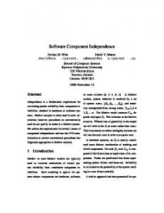
middleware technologies, and platform mechanisms supporting distributed, real-time systems [6][10]. The program is structured in two main parts. One part is addressing the definition and construction of product-lines, while the other is studying the definition and realisation of a framework capable of supporting component-based systems requiring distributed, real-time, and ultimately, continuity of service guarantees. 1.1 The SPLIT approach The product-line approach is driven by the PC&C (Produce, Consume & Customise) principle (Figure 1). One process (domain engineering) aims to produce assets such as requirements, architecture, or software components. The other (application engineering) consumes and customises assets produced during domain engineering for application development.
Develop for Reuse
L Domegacy aine cod xpe e rtis e
Domain Engineering Domain Analysis Evolution Derivation
S req pecific uire men ts
Application Analysis
Domain Design Evolution Derivation Application Design
Domain Implement. Evolution
Develop with Reuse
Derivation Application Implement.
Application
ering Application Engine
Figure 1: The product-line approach (inspired from STARS [8])
Domain engineering objective is to develop assets for reuse, while application-engineering objective is to develop with reuse. The product-line approach turns reuse from opportunistic to strategic. Flexibility is the key for product-line development in the sense that we have to study commonality and variability of assets. We must manage some assets in order to support future variants and others to be resilient to change. To attain these objectives we have adopted a process-driven but also a model-oriented approach of product-line development. At the LCAT, we are investigating a method we call SPLIT (Software Product-Line Integrated Technology). Since reuse at the code level is too complex to manage, our approach is (Figure 2): Component-based: a software component is a coherent group of software artefacts subject to assembling by third parties with an explicit specification. A software component can be considered at different levels of development (design, implementation, and delivery). The transformations for assembling are composition, splitting up, abstraction, refinement, and packaging. We focus on this issue on the rest of the paper. Architecture-centric: software component-based development is not sufficient to offer a coherent model of a product of the product-line: product-line development is not limited to software component stacking. Several people build products from a product line at different times. The problem is then to reach conceptual integrity [2] (coherence of concepts, coordination of ideas, specification drift avoidance, implementation feasibility, and adaptability). Architecture [1] and product-line architecture [3] represent a coherent mental model of the product; it is a unifying concept in developing and maintaining product lines. Requirement-driven: architecture represents a solution to a problem domain. The problem domain is represented by requirements on the product line to realise.
2
J Is the first pointer to product-line assets J Drives products’ derivation from a product-line
Requirement-driven J Is a unifying concept in developing and maintaining a product line J Enforces commonality and variability across a domain J Defines the interface glue among software components L Is a solution, not the problem
Architecture-centric
J Is a large-grain building block J Reduces risk by reusing proven software components L Does not provide a coherent mental model of the product
Component-based
ð
System approach for PL realization of software-intensive systems
Figure 2: Our approach for product line realisation Relationships between the assets product-line requirements, product-line architecture, and product-line software components, are realised by traceability means. Derivation of product-line assets for a particular product is driven by requirements. 1.2 Software components for the product line The concept of “software component” is a rather old concept in conception but its modelling and the technology to support it are new and still in emergence in research and industry. We do not focus here in the seminal works but on the recent advances in modelling and technology. Software components are now recognised as a critical element in the successful development and evolution of software-intensive systems. We agree with claims saying that software component is the right concept to promote reuse at the design level, at the implementation level and further in the life cycle. This is why so much attention is now being put on the development of conceptual frameworks for software components. As a part of our product-line approach SPLIT, the architecture step leads to specifications for a component-based design. Starting with this initial software components’ design specification, we further develop it during a new step. This step is called SPLIT-Ladder because it consists of different successive development activities, namely “design”, “implementation”, and “delivery”. These activities follow a similar development process. During this process, software components can be composed, split up, abstracted, or refined. Whereas design activity is more focused on the design of software components’ collaborations (e.g., through the development of interfaces), implementation activity is more focused on (but not limited to) implementing these collaborations. Both activities support variability, which allows adapting design and implementation, during the application engineering process, to various application-specific requirements (for example the support of different component technologies or the integration of legacy software components). The delivery activity deals with packaging, deployment, and run-time configuration. This paper is organised as follows. After presenting our main motivations in the section 2, the section 3 presents the development activities introduced just above. We present in the section 4 the meta-model describing software components and their development. Software components are composed of three structures: specification, realisation, and variability control. We present the relationships between these structures, which leads to clarifying the development process; the structures are themselves composed of assets: interfaces, contextual dependencies, collaborations, source code, deployment descriptors, etc. The section 5 presents related works before the conclusions and future work plans in the section 6.
3
2 MOTIVATIONS Our main objective is to make variability identification and realisation easier when working in domain engineering. Therefore we present an asset-based meta-model of software components for the development activities that supports a process going from a design specification down to the delivery of software components to the customer. We think that such a meta-model is needed to clarify software component-based development. This meta-model expresses three activities we name “design”, “implementation”, and “delivery”. The main characteristics of this meta-model are: -
It is generic and simple It supports a component-based development process at every abstraction level (which allows to smoothly adapt to technological context) It supports the reuse of every development part (i.e., not only code) It supports variability
The scope of this paper doesn't cover architecture issues. Every collaboration [4] that reflects an architecture choice is supposed to give result to initial component specifications. We address here the development of these software component specifications coming from the architecture. Collaborations introduced during component development activities typically cover the support for contextual dependencies or the resolution of forward variability specifications introduced during architecture. But they should never break contracts inherited from the architecture. As an important objective, we want our development meta-model to be compact while allowing rich expressiveness. Our overall asset-based approach (based on work on assets [7]) goes in this direction. On one hand, the assets contain the core information describing our software components during their transformations (e.g., assets such as provided and required interfaces, collaborations). On the other hand, the meta-model provides a simple description of the development process, which is orthogonal to the assets being transformed and to the notation used (however, we currently rely on UML [16] for the notations). The meta-model defines what a software component is as well as basic generic transformation mechanisms such as software component composition, splitting up, abstraction, and refinement. These mechanisms allow the development of arbitrarily complex software component assemblies. We also want to promote reuse of components, but not in a way limited to implementation reuse. We therefore proposed a delivery model covering the possibility to reuse whole parts of development, including design and development traceability information. We view COTS as packaged units, which may, for example, include preconfigured implementations driven by design options. Flexibility during the development is also one of our main concerns. As the different activities (and their corresponding assets) are explicated, it is easier to identify along the development process where and how COTS are to be integrated and where variability should lie, as far as product line is a concern. Business specific COTS can thus be integrated during development. COTS are adapted using necessary adaptation guidelines (e.g., patterns) provided in the form of software component assets. We plan, in the near future, to be able to integrate more complex COTS such as software component technologies (e.g., COM+ [14], EJB [11], and CCM [17]). Another important flexibility facility associated with our explicit three-step development process is the ability to delay technical choices. More generally, every development choice, which is not close to the core of the domain, can be delayed toward the end of the development process. This flexibility can be further exploited in the context of product lines.
3 ACTIVITIES OF SOFTWARE COMPONENT DEVELOPMENT In this section, we introduce the global view of the process of software component development and then detail each activity. This introduction leads to the definition of the term “software component” and to its specialisation according to three levels of software process activities. Three activities are distinguished in the development of software components, namely “design”, “implementation”, and “delivery”. The Figure 3 depicts this process at a coarse-grain level. The ellipses, the boxes and the arrows represent assets (inputs or outputs), activities, and flows of information, respectively. The inputs to the design are the design components specified in the perspective “components specification” of the software architecture [3]. The three activities have as inputs
4
the specification of the product-line computing infrastructure and the (design, implementation, or delivery 3 ) patterns mined in the domain. The three activities have as outputs some assets realising the control of the variability for the derivation. Likewise, in a component-free approach, the preparation of the delivery activity is generally part of the implementation phase. In a component-based approach, we explicitly state that the development for reuse needs a special treatment of the packaging for the development with reuse. In our approach, the assets resulting from the design activity may be delivered without the corresponding assets of the implementation. In that case, the delivery component is a design component, which is packaged to be delivered to the customer. Finally, for each activity, there is a corresponding testing activity. We choose not to show the activities “test” in the global view of the process but to include them in the former activities. The corresponding assets are part of the “white box view” of the software component (Cf. section 4 for the different views of software components).
Figure 3: Process of software components’ development
The content of the design activity includes: •
Splitting up into finer-grained design components. The reasons for the splitting up are manifold: e.g., size, insulation of functional concerns from non-functional concerns.
•
Refinement (the same asset is described with more details) to take account of the product-line computing infrastructure (e.g., choice of the software infrastructures: container, middleware, etc.) and the non-functional constraints (e.g., choice of design patterns for fault-tolerance, security).
•
Composition of several design components into a larger one. This situation should be rare. An example of such a situation is the choice for performance reasons of a COTS that covers the specifications of several design components that were initially separately specified.
•
Abstraction of COTS software components adapting them when necessary for reuse.
•
Test of design components.
The content of the implementation activity includes: •
Splitting up into finer-grained implementation components.
•
Refinement to take account of the product-line computing infrastructure (mostly, the matching with the component technology: COM+, EJB, CCM) and the non-functional constraints (e.g., choice of idioms for the construction and the management of lists of structures).
3
We introduce the concept of patterns for the delivery as there already exist patterns for the design and the implementation. For instance, the former patterns may state which assets are selected to be delivered to the customer, how these assets are packaged, configured, and deployed.
5
•
Composition of several implementation components into a larger one. This situation is also rare during implementation.
•
Abstraction of COTS software components adapting them when necessary for reuse.
•
Addition of the model elements’ adornments (e.g., in UML, visibility of attributes).
•
Translation from (UML) models to programming language source codes, to database structures, etc.
•
Writing of source codes.
•
Compilation of source codes.
•
Test of implementation components.
The content of the delivery activity includes: •
Selection and packaging of the assets that must be delivered as a coherent group: binary codes, source codes, design models, etc.
•
Configuration of the execution (e.g., runtime and deployment configuration).
•
Compilation of source codes not compiled yet.
•
Writing of the programs for the (static) deployment.
•
Writing of the usage and reference manuals.
•
Test of delivery components.
So as to adapt to the three activities, our definition of the term “software component” is generic. A software component is a group of software artefacts subject to assembly by third parties with an explicit specification. The assembly is possible during design, implementation, and delivery. The transformations that may be applicable to a software component according to the status of its development are composition, splitting up, abstraction, refinement, and packaging (see farther in the article for the definitions of these transformations). This definition is adapted from [4], [13], and [19]. A design component is a software component that may be abstracted, refined, composed, split up and / or implemented independently of the other design components. An implementation component is a software component that may be abstracted, refined, composed, split up and / or delivered independently of the other implementation components. A delivery component is a software component that may be packaged and / or instantiated independently of the other delivery components. Therefore, the generic definition of a software component allows us to use the same concept, from the design by the architect through the delivery to the customer. The Figure 4 presents an illustration of the design, the implementation, and the delivery of two software components. The two software components are identified in the software architecture. They are split up, composed, and refined during design and also during implementation. In each of these tasks, some assets are built that show and justify the decisions (e.g., collaborations, patterns, and anti-patterns). The software (design) components SC1 and SC2 lead to the software (delivery) components SC32 and SC36, respectively. During the design and the implementation, software components can be abstracted (e.g., SC18 into SC9), refined (e.g., SC6 into SC11), composed (e.g., SC4 and SC5 into SC10), and split up (SC2 into SC5, SC6, and SC7). During the delivery, the assets built during the design and the implementation are selected for delivery to the customer and packaged into delivery components (e.g., SC33 and SC6 into SC34). The tree of software components depicting the design plus the implementation is somewhat reversed to constitute the tree depicting the delivery. SC1 and SC32 address the same functionalities and non-functional aspects, but the former is the software component identified by the architect and the latter is the software component delivered by the installer to the customer. They do not contain the same assets: SC1 contains for example UML diagrams of the interfaces and the splitting up into SC3 and SC4, and SC32 contains for example binary codes, usage manuals, and also UML diagrams of the interfaces. In fact, to ease the assembly by third parties, delivery components may include assets developed during design and implementation.
6
Figure 4: Illustration of the different kinds of software components
4 SOFTWARE COMPONENT META-MODEL The objective of this section is twofold: list the assets of software components, and organise and relate these assets in a metamodel4 . First, the structuring of assets follows from the development process and the definitions of software components. Next, the assets are presented by structures. Finally, the relationships between structures show the transformation cited above: composition, splitting up, abstraction, refinement, and packaging. Structuring of software components In this subsection, we present the structures of software components, which provide a means to organise the gathering of assets corresponding to different concerns: specification, realisation of the specification, control of the variability in the specification and the realisation. This structuring applies to all kinds of software components: design, implementation, and delivery. In order to ease the development with reuse, three structures are distinguished in software components: A specification structure contains, among other assets, the required and offered interfaces that the software component must fully fulfil. This structure is necessary to allow the assembly of software components, seen as black boxes. A realisation structure is necessary to study the internal of software components, seen as white boxes. The realisation structure describes the transformation of assets from the specification structure. These transformations are abstraction, refinement, splitting up, and composition during design and implementation, and packaging during delivery. They will be detailed in the rest of the paper. A variability control structure contains, among other assets, the decision model allowing the management of the variability in the specification and the realisation structures. This structure is necessary to allow the derivation of the assets during 4
The meta-model presented here is the meta-model of the development of software components. The part of the meta-model dedicated to the execution will be developed in a future work.
7
application engineering.
Figure 5: Generic structures of software components The Figure 5 depicts this structuring in UML. A software component, be it a design, implementation, or delivery component, possesses one component specification, one component realisation, and one component variability control. The realisation structure of a design component develops only the design of the software component, not its implementation. The goal is to separate the design concerns from the implementation ones. The presence of a specification structure in implementation components states the importance of a specification of what is implemented. This specification is not redundant with the design one because they are not at the same level of abstraction. For instance, the specification of an implementation component may specify the visibility of class attributes while this detail is irrelevant at the design level. Likewise, during domain engineering, delivery components possess some variability. This variability corresponds to the different ways of delivering software components for the different products of the same product line. The variability will be resolved at derivation time that is when going from domain engineering to application engineering. Thus, there is a variability control structure in delivery components in domain engineering, and of course, no variability left in application engineering. Finally, software components may contain no realisation, for instance software components in the perspective “software components specification” in the software architecture [3] or a software component which specification is not yet realised but is going to be composed with others. Of course, a software component may contain no variability in the specification and realisation structures and may therefore have no variability control structure. Assets of structures The structures introduced so far are sets of assets. The stakeholders involved in the development of software components build assets. In the following, the assets are listed by software component types (design, implementation, and delivery) and by structures (specification, realisation). We do not present in this paper the assets of the variability control structures, nor the detailed relationships between assets (see Figure 6 for an indicative traceability between assets). Moreover, we do not claim that the list of assets is exhaustive. Finally, the assets describing the product-line computing infrastructure are also introduced. The product-line computing infrastructure is the set of software pieces or hardware pieces assumed to be already present by some stakeholders when they develop a software component. Design component specifications: Asset “interfaces”: is the specification of contracts with other design components and with the software infrastructures of the product-line computing infrastructure. The contracts are bilateral, that is a design component requires and offers services to other design components and to software infrastructures. The contract is conceptualised by interfaces, so the name of the asset is “interfaces”. Asset “contextual dependencies”: is the specification of the dependencies with the product-line computing infrastructure. These dependencies are specified before being taken into account. Contextual dependencies are taken into account by refining the design component, that is, introducing new interfaces in the preceding asset. The two assets “interfaces” and “contextual dependencies” are necessary because, at a given level of abstraction, some dependencies with the product-line computing infrastructure are specified but not already taken into account. 8
Asset “deployment”: is the specification of the locations of the design component, the data, the neighbouring design components, and the elements of the product-line computing infrastructure. These constraints gathered in the asset “deployment” might be taken into account by refining the design component: for example, adding temporal constraints on the asset “interfaces”. Asset “constraints”: is the specification of the non-functional requirements not yet specified in the preceding assets. These non-functional requirements include requirements on the execution, on quality attributes, on the qualification (method, tests), on the development, etc. When non-functional requirements are realised either by the software component or by the product-line computing infrastructure, these requirements are inputs for the refinement of the assets “interfaces”, “contextual dependencies”, and “deployment”. Design component realisations: Assets “collaboration”[4]: shows the static and dynamic relationships between internal software components of software components. This asset is used to show the composition and the splitting up of software components. Implementation component specifications: are described with the same assets as design component specifications, except that the level of details is higher. For example, the models may contain many adornments (visibility of attributes, etc.). Implementation component realisations: Asset “collaborations” as in the design realisation. Asset “classes”: shows the static and dynamic relationships between internal classes (that result initially from the analysis) of software components at the end of implementation. This asset is used to describe the internals of atomic software components –i.e., software components that are not further split up during implementation. Asset “CIDL5 code”: is a translation of the asset “interfaces” into source code. Assets “source code” and “binary code”: are the translations of the asset “classes”, respectively, into source and binary code of the internal classes. Delivery component specification: all the assets built up to the delivery activity may be part of the delivery component specification. Thus, all the assets introduced in the specification and the realisation structures of the previous activities are part of this specification. Delivery realisations: Asset “usage manuals”: is specifically written to be read by particular end-users. Asset “reference manuals”: includes the development guidelines collected during the development (design, implementation, and delivery) that are delivered. So, they also contain the development guidelines of the scripts written for the development and the documentation of the organisation of the assets present in the delivery component. There is a choice of which development guidelines are delivered and which are not, but their content may be adapted to be read by customers. Asset “descriptors” into XML6 [20]:
5
-
“software component descriptors”: is the merge of a translation of the assets “contextual dependencies”, “deployment”, and “constraints” that were not entirely taken into account during design and implementation.
-
“packaging descriptors”: describes the package organisation and the relationships between the assets. The packaging descriptors will be read by utilities to automate the deployment. Several delivery components may be assembled to form a larger delivery component.
-
“deployment descriptors”: describes the configuration of the runtime environment according to nonfunctional issues (e.g., customer-specific security parameters or timeouts), and the realisation of the last variabilities 7 that were not solved during design and implementation (e.g., a software component that can be fault-tolerant or not may be delivered not fault-tolerant for certain customers).
CIDL stands for “Component Interface Definition Language” [17]. It includes IDL plus declarations specific to software component definition.
6
The choice of XML is motivated by its use in the Sun Enterprise Java Beans and OMG CORBA Component Model.
7
This variability is not the variability between products of a product line which is specified during domain engineering.
9
Asset “deployment utilities”: are specific utilities (e.g., scripts, programs, etc.) developed for the (automatic or semiautomatic) deployment of the assets according to the asset “descriptors”.
Constraints
Deployment
Contextual Dependencies
Interfaces
Classes
Collaborations
CIDL code
Usage manuals
Descriptors -soft. comp. - packaging - deployment
Reference manuals
Source code
Binary code
Deployment utilities
Figure 6: Traceability between assets
Finally, an element of the product-line computing infrastructure is equivalent to a delivery component. So, the set of assets of its specification is the same as the one for describing the specification of a delivery component. In order to keep tracks of all the decisions taken during the development, the actions are documented with development guidelines. Design patterns describing the selected design alternatives and design anti-patterns for the rejected design alternatives are prototypical rationale.
Relationships between structures In this subsection, we express the actions introduced so far (composition, splitting up, abstraction, refinement, packaging, etc.) by the means of the relationships between the software components’ structures. The relationships between structures are depicted in Figure 7–a. This model applies to every activity of the development. The relationships during design and implementation activities are detailed in Figure 7–b, the ones concerning the delivery in Figure 7–c. In the following, we comment these relationships.
10
(a)
(b)
(c) Figure 7: Relationships between structures
Relationships between structures during the design and implementation activities The transformations during design and implementation are depicted in Figure 8. Composition in Figure 8-a: The composition is the action of transforming several specifications (in the example, Spec1 and Spec2) into a resulting specification (in the example, Spec3) that includes the structure and the behaviour of the formers. This transformation is described into assets of realisation structures (in the example, Real3), that is in “collaborations”. The decision is documented in development guidelines. Composition is a priori rather rare; a reason is for example to gather software components into a larger one already available as a COTS. Splitting up in Figure 8–b: The splitting up is the action of partitioning a software component (in the example, SC1) into software sub-components (in the example, SC2 and SC3). The splitting up into lower-level software components and the collaborations between them is described in the asset “collaborations” of the realisation structure of the initial software component. In addition, development guidelines give rationale of the splitting up. The reasons for the splitting up are manifold: e.g., size, insulation of functional concerns from non-functional concerns, etc. Refinement in Figure 8–c: The refinement is the action of adding new details to the assets of the specification of an initial software component (in the example, Spec1). This leads to a new lower-level software component’s specification (in the example, Spec2). The refinement is described in the realisation structure of the initial software component (in the example, Real1) by “collaborations”, for instance new interfaces introduced by new collaborations appearing to take account of contextual dependencies on a software infrastructure: e.g., a middleware. The reasons for the refinement are manifold: e.g., introduction or modification of interfaces to realise dependencies on a software infrastructure. This introduction or modification of interfaces is not due to the introduction or modification of functional services, but due to the taking account of, for example, contextual dependencies. In other words, the contract of the software component defined in the software architecture is not changed through design and implementation. The very reason for the introduction or the modification of interfaces is a manifestation of the fact that there is a chain of implications between the assets of the specification structures of design and implementation components. The non-functional requirements imply new deployment information and / or new contextual dependencies: e.g., “the software component must use the back-up system X on node Y for the fault tolerance”. The deployment information implies new contextual dependencies: e.g., “the version Z of the back-up system X on Y is A”. The contextual dependencies imply new interfaces: e.g., “the interfaces “store” and “restore” must be provided by the software component to store and restore the state of the software 11
component with the back-up system A”. Refinement applies also during implementation. The implementation activity ends when the specifications of atomic implementation components are refined (realised) in assets “classes” and then in assets “source code”, etc. Abstraction in Figure 8–f: This action is the reverse of refinement. This transformation is used in Figure 8–f for the reuse of COTS (e.g., specified by SpecCOTS) before the adaptation. Abstraction is necessary when the COTS do not possess assets specifying it at the right level of abstraction: e.g., the COTS contains source codes but no implementation or design models of the source codes. Development branch in Figure 8–d: The branching is the action of leaving unrealised a software component’s specification (in the example, Spec1) and then of building several software components with the same specification but with different realisation structures (in the example, Real2 and Real3). The resulting software components are variants of the unrealised one. This is a well-known form of variability used in domain engineering. The specification is written during domain engineering and it is up to application engineers to find or build fully developed software components that match to the former. The latter software components are called variants. Of course, another alternative is that domain engineers propose the variants, which may be chosen by application engineers; these variants may be COTS. The rationale for the variability is not documented in these software components but in collaborations introducing them. Practically, variation points are modelled as hotspots with attached to one side, the initial unrealised software component, and attached to the other side, the variants (if some are provided by domain engineers). Development reuse in Figure 8–e: The development reuse is the action of reusing the realisation structure of a software component that has already been developed (in the example, Real2) for the realisation of several specifications (in the example, Spec1 and Spec1’) when the specifications are shown to conform to each other. This is the most popular reuse method. Development reuse: COTS adaptation in Figure 8–f: The COTS adaptation is a more complex form of development reuse where the COTS mined to fulfil the requirements of the specification (in the example, SpecCOTS and Spec1, respectively) must be adapted with a specific software component called an adapter (in the example, Adapter) before being reused. Adaptation, plus abstraction, shows that the meta-model allows retro engineering of software components. The adaptation consists in eliciting, from the reference and the user manuals, the assets corresponding to the level of abstraction of the specification to fulfil. Thus, if the right assets do not exist, one must first build such assets by abstraction. This is the reason justifying the use of the same assets for describing the product-line computing infrastructure and describing the software components. In our approach, this assets’ building is modelled by a series of abstractions (the reverse of refinements) before the adaptation via an adapter. The retro engineering and the adaptations are documented in realisation structures of the software components, that is with collaborations, patterns, etc. The first four items are transformations of software components; the last three items are development strategies for reuse.
12
(a) Composition
(c) Refinement
(e) Development reuse
(b) Splitting up
(d) Development branch
(f) COTS adaptation and adaptation
Figure 8: Composition, splitting up, refinement, development branch, development reuse, and COTS abstraction and adaptation Relationships between structures during the delivery activity The delivery activity consists in the creation and packaging of assets reflecting the needs of the customer and the realisation of the final requirements concerning the configuration of the execution environment. The delivery activity introduces new realisation assets (e.g., usage and reference manuals, deployment descriptors and utilities). These new assets are constructed from the assets previously developed during design and implementation activities. Packaging is the action of selecting which assets built during the design and implementation activities will be delivered to the customer and of structuring these assets to be browsed by the customer. We have tried to foresee the most generic case, 13
which consists in delivering all the design and implementation assets plus the traceability information between these assets. We suggest to structure the assets in the same form as during design and implementation, that is in a graph of software components with traceability links, which indicates where actions were performed (see for example Figure 4). We would like those whole parts of development be reusable (as COTS) as is, or after slight transformations, such as removing some white box assets in order to protect competitive advantages. We think that it is interesting to be able to deliver not only implementation COTS, but design COTS as well. A COTS, as we see it, is a connex part of a development graph that has been customised (e.g. with adjunction of deployment descriptors to components) and packaged into one delivery unit. 5 RELATED WORKS J. Ning has presented last year in this workshop a meta-model [15]. His meta-model is very interesting in that it presents many concepts related to software components. Concepts are classified, on one hand, among software component, interface, and connectors concepts, and on the other hand, among type and instance concepts. Although the meta-model clarifies some issues, it doesn't account for software components as entities subject to development. Ning's meta-model is more what we call an execution meta-model, that is describing concepts related to software components as parts of running applications. Our meta-model states that software components' concepts are not limited to execution but apply during all development stages. This is why, for example, we include assets such as "collaborations" into components and describe how software components’ assets evolve from design down to delivery. In order to describe execution issues more precisely, we are currently working on an execution meta-model as a complement to our development meta-model. J. Daniels and J. Cheesman have also presented a meta-model in [5]. Their meta-model is interesting in that it proposes a link between design, implementation, installation and execution issues. The software component can be viewed at various levels of development. Although this meta-model is not complete nor fully assessed, it is an interesting first proposal. Assets and development process are however not considered much. In [18], the meta-model is oriented towards the delivery of software components. There are two “delivery styles”: “black-box delivery” with executable modules and “white-box delivery” with source code and internal models. First, our meta-model also supports the delivery of all the assets, and it goes further: one can deliver software components at the design level without assets of the implementation. Second, the delivery includes the packaging of software components into larger ones. Third, the meta-model also supports the development of software components: actions are defined with assets in inputs and outputs.
6 CONCLUSION In this paper, we have presented an approach to model the design, implementation and delivery activities of the development of a component-based design specification resulting from an architecture step. This work has been done in the context of the study, development and assessment of product line approaches, which are the core activities of the LCAT. This meta-model is currently being assessed in the context of LCAT domain experiments. These experiments cover real business applications of Thomson-CSF and Alcatel. We proposed a meta-model of the development activities of component assemblies, backed up by an asset-based description of components. Our meta-model allows the explication of the development transformations such as component composition, splitting up, abstraction and refinement. We stressed the flexibility brought by this meta-model, such as the possibility to progressively take the context dependencies into account and delay technological choices. Finally, we presented an approach to reuse as COTS, not only implementation components, but also whole parts of a component-based development, possibly including variability. Such COTS with variability can become domain-engineering building blocks for product-lines. As future work, we plan to further express variability mechanisms along the development activities, and provide a clear derivation process, backed up by a decision model. The development process will also be described more precisely. We plan to study the detailed handling of context dependencies during development. In particular, we will propose execution metamodels for current component technologies such as COM+, EJB and CCM.
7 ACKNOWLEDGEMENT We would like to thank all members of the LCAT for their insightful comments during the elaboration of this paper. 14
8
REFERENCES
[1] Bass, L. and Clements, P. and Kazman, R. “Software architecture in practice”, Addison-Wesley, 1998. [2] Brooks, F.P. “ The mythical Man-Month”, Addison Wesley Eds, 1995. [3] Boisbourdin, F., Coriat, M., and Jourdan, J. “Building product lines for software intensive systems: the SPLIT method”, SPLC1, Denver, June 2000. [4] D'Souza, D. and Wills, W. “Objects, Components and Framework with UML: The Catalysis Approach”, Addison-Wesley, 1999. [5] Daniels, J. and Cheesman, J. "Beyond UML: A Unified Model of Component Concepts", Tutorial #32 in Conference on Object-Oriented Programming, Systems, Languages, and Applications (OOPSLA), November 1999. [6] Donnan, G. and Jourdan, J. “Software architectures, product lines and frameworks”, Alcatel telecommunications review, 1st quarter 1999. [7] IBM Object-Oriented Technology Center “Developing Object-Oriented Software: An Experience-Based Approach”, Prentice Hall, 1997. [8] Gross, D.C. et al., “An Instance of the Air Vehicle Training Systems Domain: A STARS Demonstration Project”, 1994 SCS Simulation MultiConference, San Diego, April 11-15, 1994 [9] Jacobson, I. and Griss, M. and Jonsson P. “Software Reuse: Architecture, Process and Organization for Business Success”, Addison-Wesley, 1997. [10] Jourdan, J. and Coriat, M. and Salicki, S. and Jacolot, C. “Le développement de lignes de produits logiciels”, French Technical and Research Defense Review, DGA-RSTD ’00, March 2000 . [11] Matena, V. and Hapner, M. “Enterprise JavaBeans Specification”, v1.1, Preliminary, Sun Microsystems 1999. [12] Meyer, B. “Object-Oriented Software Construction”, Prentice Hall, 1997. [13] Meyer, B. “On to components”, IEEE Computer, January 1999. [14] Microsoft Corporation and Digital Equipment Corporation, “The Component Object Model Specification”, available at www.microsoft.com, Draft Version 0.9, October 24, 1995. See also COM+ Programmer’s and COM+ Administration Reference Guides of PlatformSDK documentation. [15] Ning, J. "A Component Model Proposal", Proceedings of the International Workshop on Component-Based Software Engineering, May 1999. [16] Object Management Group “ OMG Unified Modeling Language Specification”, Version 1.3, Object Management Group, June 1999. [17] Object Management Group “ CORBA Components --- Volume I”, OMG TC Document orbos/99-07-01, Object Management Group, August 1999. [18] Sterling Software “ CS/3.0: The COOL:Gen Component Standard: A Standard for Specifying & Delivering Software Components Using COOL:Gen”, Version 3.0, Part Number 2616394-0005, Sterling Software, 116 pages, September 1999. [19] Szyperski, C. “Component Software: Beyond Object-Oriented Programming”, Addison-Wesley, 1998. [20] W3C “Extensible Markup Language (XML) 1.0”, W3C Recommandation, REC-xml-19980210, February 1998.
15