µFUP: A Software Development Process for Embedded. Systems. Leif Geiger, Jörg Siedhof, Albert Zündorf. University of Kassel, Software Engineering Research ...
µFUP: A Software Development Process for Embedded Systems Leif Geiger, J¨org Siedhof, Albert Z¨undorf University of Kassel, Software Engineering Research Group, Department of Computer Science and Electrical Engineering, Wilhelmsh¨oher Allee 73, 34121 Kassel, Germany {leif.geiger, albert.zuendorf}@uni-kassel.de http://www.se.eecs.uni-kassel.de/se/
1
Introduction
Large embedded systems like manufacturing halls or complex machines usually employ quite a number of embedded control units. These control units work together either implicitly or explicitly in order to achieve an overall task e.g. manufacturing or transporting some good. In addition, the system of embedded controllers might collaborate with usual personal computers or hosts running e.g. a production control system or a web server or just control panels for production staff. Designing, implementing and running such a large system with collaborating embedded components is a challenging task due to the complexity of the overall system. Multiple disciplines as e.g. mechanical engineers, electrical engineers and software engineers may be involved. The software of different embedded controllers may be developed by different teams (from different enterprises). Different embedded controllers may utilize different technologies and programming languages, e.g. PLCs, microcontroller programmed in C, FPGAs programmed in VHDL, hosts programmed in Java running a relational database. Next, the software for the various components is developed while the target manufacturing halls or target machines (and the embedded controllers) are still under construction. From the software engineering point of view, this creates the problem that the software is employed and tested only after the mechanical and electrical components have been build. This creates a lot of time pressure for the software development team in order to get the system in production. In addition, such a setting prevents the application of modern software engineering techniques especially of iterative software development processes where new functionality is build on top of running (and validated ) old functionality. A common approach to enable concurrent development of the different embedded components is the definition of interfaces and communication protocols. The interfaces may be
provided as UML class diagrams specifying which operations are provided by which kind of component. Protocols define valid orders of messages changed between components, this may be specified e.g. with statecharts, cf. [SGW94]. Due to our experiences, interface and protocol definitions are not sufficient in order to enable concurrent development of different embedded components of some complex system. Embedded components development that way frequently do not collaborate immediately but require major adaptions during placing into operation. In order to improve this situation, we propose to develop an overall simulation of the whole system as some kind of living requirements specification. This overall simulation should provide stubs for all embedded components and it should be possible to validate the collaboration of the components by (automatic) system wide use case tests. In order to enable the development of a single embedded component prior or parallel to the development of the mechanical and electrical system elements, there should exist a (simple) simulation of all I/O devices of that embedded component. This means, we need an operational model of sensors, actors and busses attached to an embedded system at an appropriate logical level of abstraction. This allows to develop the logical control software of the embedded system in parallel to the hardware development. Combined with an overall system model, this allows to test the embedded component software in an virtual environment reflecting its planned use. As soon as the hardware for the embedded component and the mechanical components controlled by it are available, the overall simulation may be deployed in order to test the actual embedded component in the context of its later use. Step by step, the components of the overall simulation may be replaced by actual components until the overall system is in production. An component and overall system simulation may also be used for failure mode effect analysis purposes. Even for components or for a system in production, the simulation may still be exploited for failure detection and analysis. The actual system and the simulation may be run in parallel and the actual and the simulation behavior may be compared. In case of deviation, either the actual system or the simulation is malfunctioning. In the next section, we illustrate our ideas with the help of a very simple example. Then we conclude and sum up.
2
Example
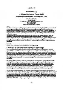
This section illustrates our ideas with the help of a simple example, a LEGO carousel storage system controlled by a Java programmable micro controller, cf. Figure 1.
Figure 1: LEGO model of a carousel storage
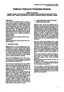
Following the test-first-principle of modern agile development processes, before we actually program the micro controller, we first set up a test scenario involving simulations of the relevant physical components. Figure 2 shows a coarse grain model of our carousel storage. The carousel consists of a set of racks where each rack consists of certain compartments where each compartment may store some good. In the scenario of Figure 2, the storage is asked to retrieve some Aspirin. In the second activity of Figure 2, the storage looks up where the Aspirin is stored using a qualified goods link. Then the train is asked to move to the position of the corresponding rack. Next the lifter has to raise to the level of the corresponding compartment and finally the pusher arm is asked to push the good our of the rack. Depending on the complexity of the train, lifter, and pusher component, these components may be controlled by a common micro controller or these components may employ their own micro controller, each. We propose to refine the behavior of each component on the level of a simulation, first, and to decide about placing of functionality on controllers, afterwards, when the complexity is known.
Figure 2: Storage model
Figure 3 shows a simple simulation scenario for the lifter component of our model. The lifter deals with sensors and actors. Implemented within an embedded controller, the lifter ’sees’ its sensors and actors through certain I/O ports, only. In our example, the sensors and actors are connected to a OneWire bus. The motor bridges are addressed via an OneWireOut port and the sensors are addressed via an OneWireIn port, cf. first activity of Figure 3.
Figure 3: Lifter model
The first activity of Figure 3 shows the OneWire ports in the middle of the object diagram. On the right there are components of the actual control software going to run on some Java micro controller. These control components get and send their signals from and through the OneWire ports. On the left of the object diagram simulation components are shown. These simulation components listen to the OneWire ports. In the first activity of Figure 3 the lifter is asked to raise to level 2, see method call on
the right. The lifter determines that it has to move upwards and therefore the lifter asks its motor to move forward. The motor sets the corresponding pin in the OneWireOut port. Now the control software has initiated the raising and it waits for signals from the rotation sensor. The simulation motor listens to its OneWireOut port and thus it is informed that the control software wants the motor to turn forward, cf. step 2 of Figure 3. To simulate the motor movement, the simulation motor periodically updates the y position of the lifter. In the third step of Figure 3, each incrementation of the y position fires a posChanged event in the listening sensors. The sensors, in our case the rotation sensor analyse the position change and change the values of the corresponding OneWireIn ports, accordingly. This again is recognized by the sensor components on the Java controller. This components believe that actually the lifter raises and that this is observed by the rotation sensor. Accordingly, the rotation sensor living in the micro controller updates its bookkeeping of the lifters positions. This again is observed by the lifter component on the micro controller. This component checks whether the desired height is reached and then it will stop the motor which will reset the corresponding output port which causes the simulation motor to stop signalling position changes.
3
µFUP
The previous section outlines an object oriented modeling of a simple carousel storage. This model employs a number of control components for the lifter, the train, the pusher and for motors and sensors. The model is described at two different levels of granularity: A coarse grain level outlining the collaboration of the top-level carousel components for the retrieval of a certain good, and a fine grained level dealing with sensors and actors of the lifter component. Our model covers the actual control components as well as the physical components. µFUP proposes the following steps in the development of such a system of embedded components: Developing an overall process simulation platform: Following our approach, one first builds the simulation at the coarse grained level. Building the simulation is conventional software development, thus e.g. the usual Fujaba process (FUP) may be employed, cf. [GSZ03b, DGMZ02]. This means, we use the Fujaba CASE tool to derive automatic JUnit tests from the scenario models. Then, we provide class diagram declarations for all kinds of objects, attributes, links and methods that are used in the scenarios. Next we follow the practical guidance of the Fujaba process and derive (manually) method behavior specifications. Using the automatic tests derived from the scenarios, the methods employed in these scenarios are validated. At the coarse grained level this results in a simulation platform for top-level processes. Refining the simulation of employed components: Provided with a simulation platform for higher level processes, now certain components may be refined, e.g. the lifter component. We again employ the usual FUP process to derive tests and implementation of the fine grained simulation. Once the fine grained model is unit tested, it may be plugged into the
higher level simulation in order to simulate it in the context of the overall process. Note, different fine grained components may be developed by different teams, concurrently. The overall simulation always serves as a functional reference architecture allowing to test the fine grained component in the overall process and interplay of multiple fine grained component simulations. Distribution of components: The final system will employ multiple embedded controllers responsible for different components of the overall system. Thus we have to decide which components will be deployed on which devices. We split this into two steps. First we distribute the overall process on multiple independent processes. Then we deploy these process on their target devices. Distributing the overall simulation on multiple process already involves the problem of inter process communication. Thus we have to decide on process communication mechanisms like CORBA or RMI, etc. In addition, the data has to be distributed on the multiple process such that each process has all its information at hand. Maybe parts of the data may have to be replicated and (mutual) update mechanisms have to be installed. Again we use the simulation of the overall system in order to validate process communication and distribution. Deployment on embedded controllers: Until now, the whole simulation may be validated on a single computer. Once the overall system has been split into multiple components we may deploy the components on different computers. This allows to validate the bus and communication infrastructure. The different components may be deployed on their actual target devices. However, if we still run it in simulation mode, sometimes a more powerful variant of a target embedded controller may be needed to cover the simulation overhead. Migrating to physical components: Once a component has reached its target embedded controller, we may replace simulation components with their physical counterparts. Our simulation architecture allows to do this in small groups, e.g. one motor and the corresponding sensors. Still, after each reconfiguration we may validate the component using the existing unit tests or employ the component in the context of the overall system. This allows to deal with sensor and actor and IO problems, step by step. Using the simulation for monitoring purposes: Once the system or a component is successfully deployed in its target configuration, we may still employ the simulation components in order to monitor the behavior of the physical components. We just continue to deploy the simulation and add a monitor component that compares the sensor signals delivered by the simulation with the signals delivered by the physical sensors. A difference beyond a certain threshold may be used as an indicator for malfunctions (either of the simulation or of the physical devices).
4
Summary
In this paper, we introduced a process for developing embedded systems. We think, that in complex embedded systems consisting of several distributed components, an overall system model is needed for testing and simulation purposes. The Fujaba CASE tool already offers tool support for modeling, simulating and testing of such system models. However,
this simulation is still done on the development machine. In section 3, we discuss how the different components may then be deployed to their target platforms. Tool support for this step is future work in the Fujaba CASE tool project. One could e.g. use UML deployment diagrams to specify the distribution of the different components. Some kind of automated CORBA or RMI stub generation for inter-process communication would be desirable, too. Our process does not yet take hard-realtime requirements into account. Such realtime aspects require additional means for simulation as offered e.g. by MatLab Simulink. To meat the realtime requirements even in the simulation, special hardware may be required. The Fujaba Tool Suite RT developed at the University of Paderborn already enables the developer to model realtime systems using so-called realtime statecharts [FRT04]. From these statecharts, Fujaba then generates JavaRT code and executes it in a simulation VM. Adding this to our process is future work. However, we believe that there are many cases that do not require hard realtime. For such systems, µFUP provides practical guidelines to deal with the distribution and process communication aspects of complex embedded systems deploying multiple communicating micro controllers.
References [DGMZ02]
I. Diethelm, L. Geiger, T. Maier, A. Z¨undorf: Turning Collaboration Diagram Strips into Storycharts; Workshop on Scenarios and state machines: models, algorithms, and tools; ICSE 2002, Orlando, Florida, USA, 2002.
[DGZ02]
I. Diethelm, L. Geiger, A. Z¨undorf: UML im Unterricht: Systematische objektorientierte Probleml¨osung mit Hilfe von Szenarien am Beispiel der T¨urme von Hanoi; in Forschungsbeitr¨age zur ”Didaktik der Informatik“ - Theorie, Praxis und Evaluation; GI-Lecture Notes, pp. 33-42 (2002)
[Fu02]
Fujaba Homepage, Universit¨at Paderborn, http://www.fujaba.de/.
[FRT04]
Fujaba Tool Suite RT Homepage, Universit¨at http://wwwcs.upb.de/cs/fujaba/projects/realtime/index.html.
[GSZ03b]
L. Geiger, C. Schneider, A. Z¨undorf: Integrated, Document Centered Modelling in Fujaba; 1st International Fujaba Days, Kassel, Germany (2003).
[KNNZ00]
H. K¨ohler, U. Nickel, J. Niere, A. Z¨undorf: Integrating UML Diagrams for Production Control Systems; in Proc. of ICSE 2000 - The 22nd International Conference on Software Engineering, June 4-11th, Limerick, Ireland, acm press, pp. 241-251 (2000).
[SGW94]
B. Selic, G. Gullekson, P. Ward: Real-time Object Oriented Modeling; ISBN 0471599174, J. Wiley & Sons (1994).
[Z¨u01]
A. Z¨undorf: Rigorous Object Oriented Software Development, Habilitation Thesis, University of Paderborn, 2001.
Paderborn,