A Software Engineering Methodology to Optimize Caching in Multi-processor DSP Architectures: TMS320C80 Results towards the Real-time Execution of Low Level Image Processing
1
Frantz LOHIER1,2 Electronique Informatique Applications Burospace, Bâtiment 4, Route de Gisy 91571 Bièvres Cedex, FRANCE
[email protected]
ABSTRACT This paper introduces an original software engineering methodology we developed while focusing on the implementation of a low-level image processing library targeted for a shared memory multi-processor DSP architecture: the TMS320C80. Real-time constraints led us to concentrate on the enhancement of data locality thanks to the software managing of caches based on an advanced multi-dimensional DMA. This contribution compares to other existing C80’s image processing libraries [1][2] in terms of genericity, flexibility, and performance improvement. Our approach allows for the composing of concurrent processing chains grounded on a modular library gathering basic processing operators. Generic mechanisms allow to address all basic operator’s requirements as well as to quickly expand the library thanks to a re-usable and well defined framework. Flexibility allows to dynamically re-configure a chain or to modify the region of interest and the number of processors. We finally demonstrate experimentally that our approach allows significant performance improvements.
2
Pr. Patrick GARDA2 Laboratoire des Instruments et Systèmes Université Pierre et Marie Curie 4 place Jussieu - B.C. 252 75252 Paris Cedex 05, FRANCE lohier|
[email protected]
1. Introduction 1.1 Today’s development constraints This paper addresses the problem of finding an efficient and generic methodology to implement real-time low-level image processing on the C80 and by extend on multi-processors DSP architectures. This work is relevant with regard to several aspects. Firstly, practical implementation of complex algorithms on such an hardware target requires a lot of efforts. At the same time, competition shortens processor’s life while the “time-tomarket” constraint is more difficult to achieve due to increased processor’s complexity. Secondly, algorithms are getting more and more computationally intensive and real-time constraints are hard to meet.
1.2 Current methodological trend Extensive research towards software engineering methodologies and architectural trade-off address these key issues. Building software libraries is one of the major trend of the past decade but even if object oriented languages favors re-using the code, they are virtually not used in the DSP industry where the code compactness or the real-time constraints are usually not compatible with such high level generic languages.
Instead various signal processing simulation environments such as PTOLEMY [3], HYPERSIGNAL [4], CapCASE [7] or MATLAB [5][6] include “hardware in the loop” features embedding simulation and code generation. Basic blocs gathered in libraries are graphically used to compose and validate various algorithms. This introduces the notion of graphical programming. Heterogeneous description domains are gradually supported whereas synchronous data flows still forms the conceptual framework. Then, and despite commercial praises, automatic code generation from high level description is still experimental and demonstrate various limitations. Whether tools are meant to support a single processor or an heterogeneous multi-processor architecture, flexible processing of multi-dimensional signals is lacking while the generic mechanisms used to warp bloc connections do not consider enhancing data locality towards performance improvement and hence require more resources or complex manual refinement steps.
1.3 Architectural evolutions On the other hand, the RISC and DSP architectures are converging towards VLIW cores featuring SIMD operations (C8X [8], C6X [10], TriMedia [11], future Merced [12]). While automatic SIMD code generation is still limited, VLIW compilers are getting mature and optimization techniques such as software pipelining or loop unrolling allow high level language to be compiled into well optimized code. Hence, data flow optimizations will be one of the most important stake of this coming years competition towards embedded systems. This emphasizes the importance of the results gained in this article. •
Caches vs DMAs
With the advent of VMAC or SIMD operations on RISC processors, what today most distinguishes a RISC from a DSP is probably the caching hardware architecture. Whereas RISC architectures feature hardware data caches, DSPs often use DMA coprocessor(s) combined with general purpose internal data memory. Although this stand as a more predictable and efficient alternative [16][17], the programming stage is also more complex. This is
emphasized with the advent of multi-dimensional DMA found on the C8X and C6X generation. •
Seeking for a generic and portable methodology
Whereas DSP programming becomes more difficult, tools or programming techniques are lacking especially while focusing on 2D processing. This general discussion led us to introduce an original methodology build around the software managing of caches thanks to an advanced multi-dimensional DMA. Moreover, our approach focuses on the real-time implementation of 2D processing on multi-processors DSP architectures. Three key concepts characterize our methodology: genericity, flexibility and performance enhancement. The next section formalizes the principal entities towards genericity. Then section 3 details how entities are combined to merge flexible processing chains. Finally, section 4 demonstrates performance improvements measured thanks to a novel C80 image processing library we implemented following our methodology.
2. A generic methodology Our methodology defines a software engineering framework built upon well defined entities and rules to manipulate and extend them. This eases code re-usability and allows for a fast and easy extension of the library. We now review these entities.
2.1 Buffers In our image processing context, a buffer stands as a ROI (Region Of Interest) with which 8 parameters are associated including the width Wref, the height Href, the physical location (@BUF) and the width pitch Wpitch. Wpitch allows us to address any 2D image sub-area without requiring an extra transfer to isolate the region. Since direct external memory addressing is very costly on the C8X (10∼15 cycles per access in the best case [9]), the DMA is used to download a specified amount of data in internal data memory where processing can take place must faster (1 cycle per access). In a software manner, we need to manage a cache per buffer with which 2 more parameters are associated: the location of an internal memory area for caching purpose (@CACHE[0]) and the size S of this area. Temporally speaking, if we now think
of overlapping raw computation with the transfer of the next bunch of data to be treated, we need to implement the double buffering technique which requires a second cache location (@CACHE[1]). This approach is meaningful thanks to the C8X’s crossbar which prevents contention between processing and transfer when distinct internal memory banks are used. The last parameter, σ, stands as the number of processors used to partition buffer’s data towards an SPMD processing scheme.
2.2 Processing node A processing node is a function executing one or several iterations of an algorithmic operator. A sequence of node implements a processing chain which consume and produce data from and to buffers. Nodes execute on the C80’s advanced DSPs or PPs for Parallel Processors and are written in assembly language that is mandatory to achieve reasonable performance. We took advantage of TI’s assembly code compactor [15] to fasten development and improve node’s performance.
2.3 The processing template The processing template runs on each PP and aims at encapsulating the synchronization and handling of DMA data transfers with the launching of nodes.
2.4 Data templates Data templates or templates are entities associated with operators. They gather parameters describing what the input and output structuring element for a processing node. We now give more insight on these parameters. •
Basic parameters and optimization issues
A n×m convolution mask would stand as the input template of a convolution node (Wt=n, Ht=m) whereas 1×1 would correspond to the output geometry. The input geometry will allow us to ensure that enough data are transferred in internal memory for at least one processing iteration. This can be dependent on the operator’s implementation itself. Focusing on 2 major optimization techniques which are loop unrolling and the use of SIMD operations, the initial template is maximized to meet the fact that several horizontal or vertical iterations of an operator are computed in parallel. If two horizontal iterations of the convolution operator are treated in
parallel, the input and output geometry are changed to (n+1)×m and 2×1 respectively. To download an amount of data consistent with the vertical and horizontal quantity required to execute a new iteration of the optimized node in either of these directions, we introduce the horizontal and vertical steps. For our n×m convolution example, the horizontal and vertical steps are Ws=1 and Hs=1 respectively whereas they would be defined as Ws=2, Hs=1 in the optimized case. Of course, nothing prevents the implementation of a node to take into account the non multiple cases ((Wref Wt) mod Ws ≠ 0) but on the one hand, the implementation gets more complicated thus longer (emphasized by the fact that PP’s VLIW algebraic assembly is difficult [8]) whereas on the other hand, the increased granularity favors instruction cache contention which is likely to decrease performance. This last remark depicts a phenomenon which much depends on the overall granularity of a chain and on the number of cache blocks required by the processing template itself. As an example, a binary NOT node shows a 30% drop of performance on a 5122 image when one instruction cache block is reloaded per DMA request. •
Overlapping templates
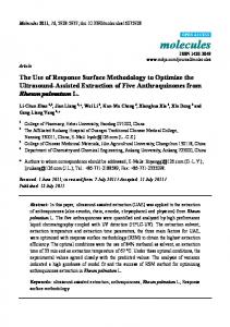
Overlapping templates defined by Wt>Ws and/or Ht>Hs require a deeper analysis. Since data are brought using multiple DMA requests, we need to cope with template’s pixels that are shared between 2 requests (Figure 1). We can either reload the data or introduce a more subtle mechanism where the node is responsible for launching the next bunch of input data once the re-using of the previous data completed. The first approach is preferred because it simplifies the node (smaller granularity) as well as the implementation of such a mechanism in a multi-node context. Furthermore, since overlapping templates are generally associated with complex node (e.g. convolution) for which processing is usually slower than transfer, longer transfers have little impact on the global processing duration. The pair (Wt,Ws) and\or (Ht,Hs) are then used to calculate the amount of data reloaded per direction, set equal to Wt -Ws\Ht -Hs.
BUFFER:
Wref 1st DMA req. Reloaded data (H t -Hs)
Href 2nd DMA req. Templates (W t=Ht=3,Ws=H s=1)
Input DMA request
CACHE (size S): input data are overwritten : Prev. kernel result Offset kernel result
Output DMA request
Figure 1: Data reloading and results offsetting Another issue that arises when dealing with convolution node is linked with the overwriting of the center data by the convolution result. This renders the next iteration calculus erroneous. Considering the concurrent transfer of the next DMA request, an intuitive approach suggests using a third memory bank to output the results while triple buffering. Offsetting the result as shown with Figure 1 is a much simpler alternative. •
The last paragraph suggests the need for an external template geometry (upper-case Wt ×Ht, Ds, Dp, Ws, Hs) which stands as the external counterpart of a node’s internal input\output template used when sweeping its associated input\output buffer. Internal input (I) and output (O) template parameters are designated in lower-case. We also define an internal data size and pitch (ds,dp) to allow reserving space between 2 data in internal memory. This simplify the implementation of nodes that expand the initial data size. The following table shows the diversity of templates configurations: Node’s name
Input template:
Output template:
wIt×hIt,dIs,dIp, wIs, wOt×hOt,dOs,dOp,wOs,hO hIs s
Optimiz a-tion
Histogram
1×1,1,1,1,1
None
FGL 1st order IIR
2×1,1,1,1,1
1×1,1,1,1,1
Binary NOT
4×1,1,1,4,1
4×1,1,1,4,1
SIMD
3x3 convolution
4×3,1,1,2,1
2×1,1,1,2,1
SIMD
Robert’s gradient
5×2,1,1,4,1
4×1,1,1,4,1
SIMD+ unrolling
Trunc. 16bits→8b
4×1,2,2,8,1
4×1,1,1,4,1
Sweeping internal and external data
2.5 Building chains C80’s DMA allows separate settings for the source and destination of a transfer. Thus we can efficiently decorrelate the way data are swept in the buffer compared to this in internal memory where data are organized linearly (to ease the linking of nodes). This feature is notably interesting for separable filters for which the same node is used whether the image is scanned vertically or horizontally. Moreover, we can think of color images for which buffer’s data alternate the coding of different color components. To pinpoint the luminance component of a YUV buffer for example, we introduce 2 more parameters which are the data size Ds and the data pitch Dp. The multidimensional feature of the DMA allows practical data filtering and permits the same node to process interlaced or consecutive data. However, since the DMA uses a 64 bits wide bus, we underline the fact that the transfer rate is reduced by Ds/8 when Ds