Nov 18, 2010 - validated by the real-time image data of brain deformation acquired by .... attenuated inversion recovery T2-weighted imaging (spin-echo se- quence ... tical surface by using a 3D LRS (RealScan USB Model 200; 3D Digital,.
Published November 18, 2010 as 10.3174/ajnr.A2288
ORIGINAL RESEARCH D.-X. Zhuang Y.-X. Liu J.-S. Wu C.-J. Yao Y. Mao C.-X. Zhang M.-N. Wang W. Wang L.-F. Zhou
A Sparse Intraoperative Data-Driven Biomechanical Model to Compensate for Brain Shift during Neuronavigation BACKGROUND AND PURPOSE: Intraoperative brain deformation is an important factor compromising
the accuracy of image-guided neurosurgery. The purpose of this study was to elucidate the role of a model-updated image in the compensation of intraoperative brain shift. MATERIALS AND METHODS: An FE linear elastic model was built and evaluated in 11 patients with craniotomies. To build this model, we provided a novel model-guided segmentation algorithm. After craniotomy, the sparse intraoperative data (the deformed cortical surface) were tracked by a 3D LRS. The surface deformation, calculated by an extended RPM algorithm, was applied on the FE model as a boundary condition to estimate the entire brain shift. The compensation accuracy of this model was validated by the real-time image data of brain deformation acquired by intraoperative MR imaging. RESULTS: The prediction error of this model ranged from 1.29 to 1.91 mm (mean, 1.62 ⫾ 0.22 mm),
and the compensation accuracy ranged from 62.8% to 81.4% (mean, 69.2 ⫾ 5.3%). The compensation accuracy on the displacement of subcortical structures was higher than that of deep structures (71.3 ⫾ 6.1%:66.8 ⫾ 5.0%, P ⬍ .01). In addition, the compensation accuracy in the group with a horizontal bone window was higher than that in the group with a nonhorizontal bone window (72.0 ⫾ 5.3%: 65.7 ⫾ 2.9%, P ⬍ .05). CONCLUSIONS: Combined with our novel model-guided segmentation and extended RPM algorithms,
this sparse data-driven biomechanical model is expected to be a reliable, efficient, and convenient approach for compensation of intraoperative brain shift in image-guided surgery. ABBREVIATIONS: BC ⫽ boundary condition; CG ⫽ conjugate graduate; FA ⫽ flip angle; FE ⫽ finite
element; LRS ⫽ laser range scanner; min ⫽ minimum; NRR ⫽ nonrigid registration; PDE ⫽ partial differential equation; PRF ⫽ patient reference frame; RPM ⫽ robust point matching
Received May 15, 2010; accepted after revision July 16. From the Department of Neurosurgery (D.-X.Z., J.-S.W., C.-J.Y., Y.M., L.-F.Z.), Huashan Hospital, Shanghai Medical College, Fudan University, Shanghai Neurosurgical Center, Shanghai, P.R. China; Digital Medicine Research Center of Fudan University, Shanghai Key Laboratory of Medical Imaging Computing and Computer Assisted Intervention (C.-X.Z., M.-N.W., W.W.), Shanghai, P.R. China; and Department of Computer Science (Y.-X.L.), College of William & Mary, Williamsburg, Virginia. Dong-Xiao Zhuang and Yi-Xun Liu contributed equally to this work. This project was sponsored by the Ministry of Health of China (2007–2009) and the National Natural Science Foundation of China (Project No. 30600639). Please address correspondence to Liang-Fu Zhou, MD, Department of Neurosurgery, Huashan Hospital, Shanghai Medical College, Fudan University, Shanghai Neurosurgical Center, 12 Wulumuqi Zhong Rd, Shanghai, 200040, P.R. China; e-mail: lfzhouc@yahoo. com.cn Indicates open access to non-subscribers at www.ajnr.org DOI 10.3174/ajnr.A2288
cortical shift during surgery showed that the displacements of brain surface ranged from 1.2 to 20 mm in the direction of gravity.1-4 Moreover, brain shift occurs not only on the surface but also in the deep brain structures.3,4 Thus, increasing concern has been generated concerning intraoperative brain deformation, which significantly compromises the accuracy of neuronavigation. Hitherto, techniques available for the compensation of brain deformation fell into 2 categories: intraoperative imaging (CT, MR imaging, or sonography) and NRR.5-18 Among these, CT and sonography are not extensively applied on direct intraoperative imaging because of their low image resolution of soft tissue. Although intraoperative MR imaging12-18 provides the best solution for brain deformation, it is not widely applied due to its high cost and long image-updating time. NRR19-33 is expected to be a promising alternative in accounting for brain deformation. NRR can be classified into 2 categories based on the intraoperative devices: surface methods and volume methods. Surface methods use a device (eg, LRS) to obtain the surface deformation and then apply this surface deformation on a biomechanical model to derive the entire brain deformation. Volume methods use intraoperative CT6 or sonography7-11 to obtain intraoperative brain images (low-resolution images) and then use these to deform preoperative MR imaging by NRR. In this article, we present a robust brain-shift framework based on a linear elastic model and implemented in our 3DIMAGE system. The compensation accuracy of this model was validated by the real-time image data of brain deformation AJNR Am J Neuroradiol ●:● 兩 ● 2011 兩 www.ajnr.org
Copyright 2010 by American Society of Neuroradiology.
1
ORIGINAL RESEARCH
mage-guided surgery has been widely used in neurosurgical units in the past decade. As an important milestone in the development of contemporary neurosurgery, navigation has significantly improved the accuracy and the safety of surgery. Most of the current systems, however, were unable to provide absolute real-time navigation because of the assumption that the brain being operated on is rigid. The preoperatively acquired 3D data were registered to the patient coordinate system. In fact, the brain tissue is nonrigid, and brain deformation always occurs in the course of surgery owing to the biomechanical property of brain tissue, gravity effect, variation of intracranial pressure, and surgical maneuvers. The laboratory studies from ours and other teams that monitored
BRAIN
I
acquired from the PoleStar N20 iMRI system (Medtronic Navigation, Louisville, Colorado). Materials and Methods Patient Population Eleven patients (10 males and 1 female; age range, 9 – 66 years; mean, 48.5 ⫾ 19.3 years) who underwent intraoperative MR imaging⫺assisted supratentorial lesion resection in our center between February and March 2008 were enrolled in this study. All patients were eligible for surgery on the basis of clinical and radiologic evaluations and complied with the protocol after providing informed consent. The study was approved by the ethics committee of Fudan University. Among the lesions, 9 were located in the cerebral hemisphere (5 in the frontal lobe, 2 in the temporal lobe, 1 on the parietal convexity, 1 in the occipital lobe) and 2 were located at the skull base (1 at the anterior skull base, 1 in the sella region). All patients underwent supratentorial craniotomies (7 frontal, 2 temporal, 1 parietal, and 1 occipital). The surgical postures included supine position (7 cases), lateral position (3 cases), and prone position (1 case). The size of the bone windows ranged from 40 ⫻ 50 to 126 ⫻ 52 mm2; mean, 4447.27 ⫾ 1277.23 mm2. Six bone windows were horizontal, while 5 others were nonhorizontal with an angle between 0° and 45° to the ground.
Computerized Medicine, Third Military Medical University, PLA, Chongqin, China). To align this model with the preoperative images, we designed a graphic user interface, allowing the user to interact with the model. The idea behind this method is to transform the operations of the mouse on the screen into the operations in the image space. First, the user moves the model close to the MR images by dragging it with the mouse (translation transform). Then, by rotating (rotation transform) and zooming in or out (scaling transform), the orientation and size of the model can be adjusted to be as similar to the MR images as possible. After these operations, the model provided an initial estimation of the position and shape of the brain (Fig 1A, -B). Refined Segmentation with Level Set. After the first step, we obtained an initial brain surface, which was very close to the MR imaging surface. Then the level set method was used for a more precise result. “Level set” is a numeric method for tracking the evolution of contours and surfaces.34 The level set function ⌿(X,t) is evolved under the control of a differential equation, 1)
where F is a speed function. To make the front maintain its smoothness, one should move in the interior of the object and then stop at the boundary. F is defined as 2)
Acquisition of the Preoperative Image In our routine neuronavigational procedure, fiducial markers were attached to the scalp of each patient and the preoperative MR imaging was performed 1 day before the operation. The 3D neuronavigational MR imaging dataset was acquired with a 3T whole-body MR imaging scanner (Signa VH/i; GE Healthcare, Milwaukee, Wisconsin) by using a T1-weighted 3D fast-spoiled gradient recalled sequence after intravenous contrast administration of gadolinium-diethylene-triamine pentaacetic acid. The parameters were as follows: TR, 11.7 ms; TE, 5.1 ms; FA, 20°; thickness, 1.25 mm; matrix, 320 ⫻ 224 pixels; FOV, 240 ⫻ 240 mm; NEX, 1. On each patient, 75–135 contiguous nonoverlapping axial sections were acquired from the top of the head to the tip of the nose for a complete coverage of the whole operating field and all fiducial markers. For some nonenhancing lesions, fluidattenuated inversion recovery T2-weighted imaging (spin-echo sequence; TR, 8500; TE, 120; TI, 2250 ms; FA, 90°; FOV, 240 ⫻ 240 mm; matrix size, 320 ⫻ 224 pixels; section thickness, 2 mm; NEX, 2; axial section) was performed when the operating neurosurgeon considered it appropriate.
⌿ t ⫹ F兩ⵜ⌿兩 ⫽ 0,
F ⫽ S共 g兲
共 1 F A ⫹ 2 F G 兲,
where g is the magnitude of the image gradient of image I. S(g) is a nonlinear mapping function to map the lower magnitude of the gradient (interior of the object) to 1.0 and the higher magnitude of the gradient (boundary of the object) to 0. FA is a constant advection speed, and FG, depending on the local curvature of the front, is used to maintain the smoothing of the front.
Mesh of the Segmented Brain
Construction of the FE Linear Elastic Model
After segmentation, the continuous problem domain (brain) needs to be discretized into connected elements with a mesh-generation algorithm. In this study, tetrahedra, instead of hexahedra, were used as the elements to express the brain surface accurately. Additionally, for the purpose of reducing the computational time and maintaining higher computational accuracy, we adopted a multiresolution mesh-generation algorithm presented by Ferrant et al.27 This algorithm combines the Octree algorithm with the marching tetrahedron algorithm. It generates the mesh with higher attenuation on the boundary and lower attenuation in the internal area (Fig 1C, -D). To improve the computational efficiency, this algorithm uses the case table to record all cases of dividing and clipping.
Segmentation of Brain
FE Equations and Acquisition of BC
Before constructing the FE model, the problem domain (ie, the brain) needs to be specified. As a crucial procedure in this framework, the segmentation of the brain influences not only the accuracy of mesh generation but also surface tracking. To obtain an accurate segmenting result, we designed a novel model-guided segmentation algorithm, which is composed of 2 steps: coarse segmentation and refined segmentation. Model-Guided Coarse Segmentation. This algorithm aligned a well-segmented brain model with the preoperative MR images of each patient to get an initial segmentation. The segmented model was generated by delineating the boundary section by section on a virtual human brain dataset from the Chinese Visible Human (Institute of 2
Zhuang 兩 AJNR ● 兩 ● 2011 兩 www.ajnr.org
After the problem domain is discretized, the linear elastic model can be approximated as a linear system of equations by the FE method: 3)
Ka ⫽ P,
where K is a structure rigid matrix, P is a structure load vector, and a is node displacement vector. BC needs to be applied to equation 3, to get a unique-solution a. In this framework, surface deformation is taken as the BC. The initial surface is extracted from the mesh of the preoperative image. The deformed surface can be acquired by scanning the exposed cortical surface by using a 3D LRS (RealScan USB Model 200; 3D Digital, Sandy Hook, Connecticut). The procedures were as follows:
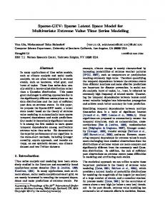
Fig 1. A and B, Model-guided segmentation. The model (green) is aligned with the preoperative MR imaging to get a primitive result with a contour (bright gray) very close to the real contour (dark gray). C, Coarse mesh. D, Multiresolution mesh.
1) After endotracheal intubation and general anesthesia, the patient’s head was fixed on a dedicated MR imaging– compatible holder to which the PRF was attached. Then the 3D preoperative MR imaging datasets were loaded into our 3DIMAGE system, which had been integrated in the Surgical Navigation System/Excelim-04 (Shanghai Fudan Digi-Medical Technology, Shanghai, P.R. China) (Fig 2A). The fiducial markers were registered by tracking the PRF. 2) The magnet of PoleStar was raised to the scanning position, and the magnet reference frame attached on the magnet was tracked by the Polaris (an infrared navigation camera). First, an 8-second e-steady scanning was performed to confirm that the area of interest was included in the FOV. Then a series of preoperative images typically including a 6.5-minute T1-weighted image and an 11-minute contrast-enhanced T1-weighted image was acquired. The thickness of sections were 3 and 2 mm, respectively. 3) After preoperative imaging was completed, the magnet was lowered beneath the table. Craniotomy was then performed in the usual way until the dura was opened. The LRS was moved into position and registered by tracking the infrared reference frame attached to it. Then the LRS was opened, and the deformed brain surface was scanned (Fig 2A, -B). 4) In surface tracking, both the initial surface and the deformed surface were represented by point sets. Tracking of the moving surface involved the following 2 steps: Registering the LRS Space with the Image Space. The initial and deformed surfaces needed to be transformed into the same space first, to track the movement of the brain surface. There are a total of 5 coordinate spaces in the operating room: image space, LRS space, Polaris space, reference frame space, and tracked tool space. With the
neuronavigation system, we transformed the deformed surface, which was acquired in LRS space, into the image space (Fig 2C, -D). 2) Surface Tracking. After the 2 surfaces were transformed into 1 space, the surface deformation needed to be computed. We designed a surface-tracking algorithm by extending the classic RPM algorithm.35 Primarily, a brief review was conducted for this RPM algorithm combined with the data used in our method. We defined the initial surface as source point set X and the deformed surface as target point set Y. These consisted of points {xi,i⫽1,2,...M} and {yj,j⫽1,2,...N}, respectively. The goal was to find the correspondence point yj of xi and the nonrigid transformation f, which was used to map xi to yj. The energy function was motivated as
冘冘 N
4)
min E共C, f 兲 ⫽ min c,f c,f
M
冋冉 冊 冉 冊 冉 冊册
c ij 储 y j ⫺ f共 x i 兲储 2 ⫹ 兰兰
j⫽1 i⫽1
⫹2
⭸ 2f ⭸ x⭸ y
2
⫹
⭸ 2f ⭸ x2
⭸ 2f ⭸ y2
2
2
which is subject to 兺jN⫽ 1cij ⫽ 1 for i{1,2,...M} and cij{0,1}. cij was used to measure the correspondence between xi and yj. The second item imposes a smoothing constraint on f and is balanced by parameter . The expectation-maximization method was used to solve C and f simultaneously. The disadvantage of this classic RPM algorithm is that it is incapable of dealing with the outliers existing in both point sets. To compensate for brain shift, we used 2 point sets. One represented the scanned cortical surface by using LRS and the other represented the extracted surface from mesh generation. Each contained many outliers. To overcome this difficulty, we defined a range ⍀R, which is a sphere centered at the source point with radius R and only took into AJNR Am J Neuroradiol ●:● 兩 ● 2011 兩 www.ajnr.org
3
Fig 2. A, Surface scanning by LRS (left) after registration with the Excelim-04 system (middle) and PoleStar N20 iMRI system (right). B, The deformed surface (right side) acquired by LRS scanning. C, Transformation from the LRS space to the image space. D, Registration of the initial surface with the deforming surface.
account the target points located in this sphere. The search range basically makes the surface tracking act as a multiresolution registration. As the range reduces, the registration will move from the coarse level to the fine level. The R plays a role similar to that of the temperature T of the simulated anneal technique used in Chui and Rangarajan,35 but our method is more computationally efficient because it only considers the target points located in ⍀R. For each source point si, we assume that its potential correspondences are subject to Gaussian distribution (as shown in equation 5). Cij is defined as the probability with which the point Si corresponds with tj located in ⍀R. It can be calculated as 5)
c⬘i j c ij ⫽ k ⫽ m , c⬘i j ⫽
冘
k⫽1
c⬘i j
1
R 冑2
冉
exp ⫺
冊
共t j ⫺ s i 兲 2 , 2 R2
᭙ t j ⍀ R , j ⫽ 1...m. The outliers in both point sets can be effectively rejected by using this search range. For each source point, we found target points within the search range ⍀R. If there were no target points for this source point, we marked it as outlier. For the outliers in the target point set, if they were out of the range, they were not involved in the computation. So, this method can be used to deal with the outliers in both point sets. After we got surface deformation, we could apply it to equation 3 directly to obtain a unique solution. The predictive deformation was visualized by different-colored meshes as in Fig 3A, and the warped image was visualized by the ray casting method (Fig 3B).
Validation of the Framework In this study, due to the PoleStar N20 iMRI system, the compensation accuracy of this linear elastic model can be validated by the real-time data of brain deformation during the surgery (Fig 2A). The validating procedures were as follows: 4
Zhuang 兩 AJNR ● 兩 ● 2011 兩 www.ajnr.org
1) After finishing the cortical scanning by LRS and the operating field draping, the scanner of PoleStar was raised to the previous scan position (inherent memory in the PoleStar system) and the second intraoperative MR imaging was performed to get the deformed image after craniotomy. 2) We input the intraoperative MR imaging data into our 3DIMAGE system, and then we registered the preoperative high-field MR image, the intraoperative low-field MR image, and the predictive image of brain shift by this biomechanical model to the same space by using the fiducial markers on the scalp and several firm anatomic markers. Before validation, all of the preoperative, predictive, and the intraoperative MR images were regularized with spacing 1 ⫻ 1 ⫻ 1 mm3 by an interpolation algorithm. 3) Two groups of deformation markers (2 markers for each group) were selected to calculate the compensation accuracy of the model. The subcortical group included some morphologically special points on the surface of the tumor and some subcortical vascular bifurcation points with obvious enhancement. The deep group included the frontal horn, temporal horn, and occipital horn of the lateral ventricle, foramen of Monro, and the choroid plexus of the triangular region of the lateral ventricle. To alleviate the subjective error and the interobserver variability, an anatomist, a neurosurgeon, and a neuroradiologist were invited to select the deformation markers separately. All of these points could be identified on the corresponding section from the preoperative and intraoperative images by every observer. 4) The real displacement and the predictive displacement of every marker were calculated by using norm-2. Definition 1: prediction error ⫽储B⫺C储2, Definition 2: compensation accuracy ⫽ (储C⫺A储2C⫺B储2//储C⫺A储2,
Fig 3. A, The predictive deformation of mesh. The red mesh represents the preoperative surface, the blue mesh represents the deformed surface, and the yellow arrow indicates the direction of gravity. B, 3D visualization of the deformation field by the ray casting method (above) and the final warped MR images (below). The magnitude of the deformation increases as the color changes from dark red to bright red; the blue arrows near the frontal lobe indicate the direction of the deformation.
where A represents the preoperative position of the marker, B represents the predictive position computed by our framework after brain shift, and C represents the real position revealed by intraoperative MR imaging. For each case, the mean value of the 4 markers was taken as the value of the model. 5) Representative data are shown as means ⫾ SD. Statistical analysis was conducted by using the Statistical Package for the Social Sciences software, Version 14.0 (SPSS, Chicago, Illinois).
Results The mean prediction error, real displacement, and compensation accuracy of the 4 markers of each case are shown in Table 1. The comparison between the subcortical markers and the deep markers is shown in Table 2. The prediction error of this model ranged from 1.29 to 1.91 mm (mean, 1.62 ⫾ 0.22 mm). The compensation accuracy ranged from 62.8% to 81.4% (mean, 69.2 ⫾ 5.3%). The real displacement of the subcortical markers was larger than that of
Table 1: Result of model validationa Patient No. 1 2 3 4 5 6 7 8 9 10 11
Prediction Error (mm) 1.78 1.49 1.91 1.29 1.60 1.73 1.31 1.65 1.73 1.90 1.39
Real Displacement (mm) 5.27 4.54 6.22 4.39 5.22 4.39 4.79 4.51 5.90 7.61 7.29
Compensation Accuracy (%) 66.0 66.9 68.1 70.0 66.6 62.8 72.1 63.3 69.6 74.0 81.4
a
All the values are mean values of the 4 markers of each patient.
the deep markers (6.56 ⫾ 1.93 mm:4.37 ⫾ 0.77 mm, P ⬍ .01). The prediction error on the displacement of the subcortical AJNR Am J Neuroradiol ●:● 兩 ● 2011 兩 www.ajnr.org
5
Table 2: Comparison between subcortical and deep markers (paired t test) Mean ⫾ Subcortical 1.78 ⫾ 0.33 6.56 ⫾ 1.93 71.3 ⫾ 6.1
Prediction error (mm) Real displacement (mm) Compensation accuracy (%)
Mean ⫾ Deep 1.46 ⫾ 0.24 4.37 ⫾ 0.77 66.8 ⫾ 5.0
Table 3: Comparison of compensation accuracy between the horizontal and nonhorizontal bone window group
Horizontal Nonhorizontal
Mean (%) 72.0 65.7
SD (%) 5.3 2.9
No. 6 5
T 2.365
df 9
P Value .042
markers was higher than that of the deep markers (1.78 ⫾ 0.33:1.46 ⫾ 0.24 mm, P ⬍ .05). The compensation accuracy on the displacement of the subcortical markers was higher than that of the deep markers (71.3 ⫾6.1%:66.8 ⫾ 5.0%, P ⬍ .01). Moreover, the compensation accuracy in the group with a horizontal bone window was higher than that in the group with a nonhorizontal bone window (72.0 ⫾ 5.3%:65.7 ⫾ 2.9%, P ⬍ .05) (Table 3). The fiducial-based registration error of each case ranged from 1.10 to 1.99 mm, mean 1.57 ⫾ 0.28 mm, and it was controlled under 1 mm within the operating field. Discussion Dynamically updating the navigational image data via a computational brain model has been proved to be a potential approach to correct brain-shift error.18,20-33 Compared with intraoperative imaging, this method may be more favorable for its convenience and time savings. Furthermore, it is more applicable because the software modules can be integrated into a commercial neuronavigational system without relying on an expensive intraoperative imaging system. The models that are used to account for brain shift fall into 3 categories: a freeform model, a physical model (linear and nonlinear), and a statistical model. Rueckert et al36 provided a free-form model based on Bsplines. To reduce computational complexity, this technique uses a lattice of control points to represent the continuous deformation field. Compared with a physical model, this model has no assumption as to physical properties. In contrast to thin-plate splines or elastic-body splines, B-splines are locally controlled, making them computationally efficient even for a large number of control points. In particular, the basis functions of cubic B-splines have a compact support (ie, changing a control point only affects the transformation in the local neighborhood of that point). However, the free-form model is not suitable for the surface-based brain shift because it is incapable of estimating the shift far away from the sparse intraoperative data (deformed surface). Miga et al20 proposed a computational model based on a consolidation theory, which is characterized by an instantaneous deformation at the contact area followed by subsequent additional displacement with time as interstitial fluid drains in the direction of strain-induced pressure gradients (ie, from high to low pressure). Sun et al21 adopted a similar poroelastic brain model by using the Biot consolidation formulation37 to simulate the brain as an elastically deformable porous me6
Zhuang 兩 AJNR ● 兩 ● 2011 兩 www.ajnr.org
No. 11 11 11
T 2.930 3.994 3.220
df 10 10 10
P Value .015 .003 .009
dium. The solution to the model equations was obtained by applying the known boundary and volumetric forcing conditions. These consolidation theory⫺based nonlinear models are capable of realistically describing the behavior of the brain. However, it is difficult to estimate the drainage of CSF to get the body force. A nonlinear hyperviscoelastic mechanical model was proposed by Witek el al and Miller.22,38 Their rheologic experiments make a significant contribution to the understanding of the physics of the brain tissue, and their extensive investigation into brain tissue engineering shows very good concordance of the hyperviscoelastic constitutive equation with the experiments both in vivo and in vitro. This model is capable of simulating the deformation of the cortex and subcortical structures. It can be applied in large-scale FE simulations and, therefore, offers the possibility of developing a biomechanically accepted detailed surgical planning and training system. A practical difficulty associated with these nonlinear models, including the consolidation theory⫺based model, is that an excessive amount of time is needed to seek the solution of the constitutive equation. Davatzikos et al23 proposed a statistical model based on precomputing the main modes of brain deformation by using a biomechanical model. Recent extensions of this framework showed promising results for intraoperative surgical guidance based on sparse data.24 Although these statistical models are computation-efficient, their accuracy needs to be further evaluated. One solution for the trade-off between accuracy and computation time is to use the linear elastic model. This method has been used by many groups to compensate for soft-tissue deformation.25-33 Although it is inferior to the nonlinear model in describing the behavior of the brain, the linear elastic model is more computation efficient and the solution of the constitution equation can be found in a reasonable amount of time. The volumetric results could be obtained by relying solely on the direct measurement of the cortical surface as a displacement BC.25 This BC is much easier to obtain than that of the consolidation theory model. On the basis of these factors, a linear elastic model was chosen in our work. To build a more efficient linear model, we made some modifications to the segmentation and the surface-tracking algorithm. First, a novel model-guided algorithm was designed to segment the brain out of the skull. This algorithm aligned a well-segmented brain model acquired from a virtual human dataset with the patient’s brain MR imaging to get an initial segmentation. Then, the level set method was used to refine the initial segmentation. In our study, this modelguided method of segmentation has proved more efficient for solving the problem of the initial contour in level set. Second, to drive this model, we designed a surface-tracking algorithm by extending the classic RPM algorithm to deal with the outliers in both the source point set (initial surface) and the target point set (deformed surface) by a Gaussian
distribution⫺based search range. In our implementation, the surface of the preoperative image was extracted as the initial surface because it can be represented with mesh nodes, which makes it possible to apply the BC on FE equations directly. The FE model requires a long time for computing the deformation, which hampers its routine clinical use. To overcome this difficulty, we adopted a multiresolution mesh-generation algorithm. This algorithm is characterized by decomposing the inhomogeneous region into smaller elements to retain the accuracy but decomposing the homogeneous region into larger elements to reduce the total number of the elements, and, therefore, to reduce the computation time. Furthermore, the message passing interface⫺based parallel computing was used to maximize the parallel computing power of a workstation in our method. The Portable, Extensible Toolkit for Scientific Computation, a well-known parallel scientific computing library,39 is used to solve the FE linear system of equations. Evaluation of the clinical application of a method for correcting brain shift error in neuronavigation should be based on the following criteria: 1) Acceptable Compensation Accuracy In this study, validated by the criterion standard real-time intraoperative MR imaging, the compensation accuracy of our framework averaged 69.2 ⫾ 5.3% (71.3 ⫾ 6.1% on the subcortical structures and 66.8 ⫾ 5.0% in the deep structures). This means the registration error caused by brain shift under conventional neuronavigation was significantly reduced (from an average of 5.47 to 1.62 mm), making it sustainable for clinical acceptance. 2) Real-Time Image Updating Benefiting from the multiresolution mesh-generation algorithm and parallel computation, the computation time of the FE model in our workstation (Intel Core2 Duo E6850 4GB RAM) ranged from 43 to 56 seconds (mean, 48.3 ⫾ 4.2 seconds). The image-processing time (from mesh to gray image) was steadily around 22 seconds. Therefore, the duration of the whole image⫺updating process (including LRS scanning, surface tracking, model computing, and image processing) can be controlled within 15 minutes, which is shorter than intraoperative MR imaging time.37 Because our 3DIMAGE system has been integrated into a conventional neuronavigation system, during the operation the preoperative images can be immediately updated by the deformed images to guide the surgical procedures. 3) High Image Quality Because the original image data were acquired from high-field MR imaging (3T) preoperatively, the final updated gray image, which was generated from the FE equation computation and a trilinear interpolation algorithm, demonstrated a similar soft-tissue resolution to the preoperative image, which is significantly higher than the image from intraoperative sonography, CT, and low-field intraoperative MR imaging. In addition, with in-depth analysis of the results of model validation, we found that our framework showed a higher prediction error on the subcortical structures than in the deep structures (1.78:1.46 mm, P ⬍ .05). Nevertheless, a higher
compensation accuracy was observed on the subcortical structures than in the deep structures (71.3%:66.8%, P ⬍ .01). This phenomenon indicates that the absolute value of prediction error might be determined by the magnitude of displacement (for the real displacement of subcortical markers is significantly larger than that of deep markers, P ⬍ .01), and the relative rate of compensation accuracy might be determined by the distance from the marker to the brain surface, which serves as the BC to drive this model. There were several limitations for this study. First, the spatial resolution of the preoperative and intraoperative images and the fiducial-based registration error will inevitably bias our validation results. Because these kinds of errors may not be in the same spatial direction as the error caused by brain shift, they cannot be simply added up. Therefore, it is difficult for us to evaluate how much and to what extent these biases will influence the validation result. Second, the linear elastic model driven by surface information mainly simulates the brain deformation induced by physical factors (such as gravity effect, CSF loss, and so forth). For the deformation caused by surgical manipulations, such as tissue resection and retraction, volume methods (eg, intraoperative sonography) based on NRR may be more favorable. For other types of deformation that are caused by pathophysiologic factors such as tumor growth, edema around lesions, administration of dehydration drugs and anesthesia, and so forth, there has been no perfect solution so far. Third, because the brain deformation patterns are complex, which may occur not only on the surface but also in deep brain structures, the principal direction of displacement does not always correspond with the direction of gravity. Therefore, the simple computational algorithms that use limited intraoperative information (eg, brain-surface shift) will not always accurately predict the whole-brain deformation. Finally, recovery of softtissue deformation depends on a reliable biomechanical model. The model we used in this study, though allowing local parameter control, is still a homogeneous model. Hence, the development of a heterogeneous biomechanical model, more specifically the development of a multimaterial mesh-generation algorithm and the estimation of the material properties, will be helpful to improve our framework in future studies. Conclusions In this article, a biomechanical model was used to compensate for the intraoperative brain shift in neuronavigation. Due to some effective modifications, this linear elastic model is likely to be a reliable, efficient, and convenient approach to correct the brain shift error during image-guided surgery. Although our 3DIMAGE system has been integrated into a self-developed traditional navigation system, there is still much work needed to improve the accuracy and feasibility of this technology before it could be applied in the operating room.
Acknowledgments We thank Jian-bing Shi for technical support in the navigational procedure and intraoperative MR imaging manipulation. AJNR Am J Neuroradiol ●:● 兩 ● 2011 兩 www.ajnr.org
7
References 1. Roberts DW, Hartov A, Kennedy FE, et al. Intraoperative brain shift and deformation: a quantitative analysis of cortical displacement in 28 cases. Neurosurgery 1998;43:749 – 60 2. Hill DL, Maurer CR Jr, Maciunas RJ, et al. Measurement of intraoperative brain surface deformation under a craniotomy. Neurosurgery 1998;43:514 –28 3. Dorward NL, Alberti O, Velani B, et al. Postimaging brain distortion: magnitude, correlates, and impact on neuronavigation. J Neurosurg 1998;88:656 – 62 4. Du GH, Zhou LF, Mao Y, et al. Intraoperative brain shift in neuronavigatorguided surgery. Chin J Minim Invasive Neurosurg 2002;7:3– 6 5. Gumprecht H, Lumenta CB. Intraoperative imaging using a mobile computed tomography scanner. Minim Invasive Neurosurg 2003;46:317–22 6. Nakao N, Nakai K, Itakura T. Updating of neuronavigation based on images intraoperatively acquired with a mobile computerized tomographic scanner: technical note. Minim Invasive Neurosurg 2003;46:117–20 7. Trobaugh JW, Richard WD, Smith KR, et al. Frameless stereotactic ultrasonography: method and applications. Comput Med Imaging Graph 1994;18:235– 46 8. Jodicke A, Deinsberger W, Erbe H, et al. Intraoperative three-dimensional ultrasonography: an approach to register brain shift using multidimensional image processing. Minim Invasive Neurosurg 1998;:41:13–19 9. Comeau RM, Fenster A, Peters TM. Intraoperative US in interactive imageguided neurosurgery. Radiographics 1998;18:1019 –27 10. Unsgaard G, Ommedal S, Muller T, et al. Neuronavigation by intraoperative three-dimensional ultrasound: initial experience during brain tumor resection. Neurosurgery 2002;50:804 –12 11. Lindseth F, Lango T, Bang J, et al. Accuracy evaluation of a 3D ultrasoundbased neuronavigation system. Comput Aided Surg 2002;7:197–222 12. Moriarty TM, Kikinis R, Jolesz FA, et al. Magnetic resonance imaging therapy: intraoperative MR imaging. Neurosurg Clin N Am 1996;7:323–31 13. Wirtz CR, Bonsanto MM, Knauth M, et al. Intraoperative magnetic resonance imaging to update interactive navigation in neurosurgery: method and preliminary experience. Comput Aided Surg 1997;2:172–79 14. Wirtz CR, Knauth M, Staubert A, et al. Clinical evaluation and follow-up results for intraoperative magnetic resonance imaging in neurosurgery. Neurosurgery 2000;46:1112–22 15. Nimsky C, Ganslandt O, Tomandl B, et al. Low-field magnetic resonance imaging for intraoperative use in neurosurgery: a 5-year experience. Eur Radiol 2002;12:2690 –703. Epub 2002 May 1 16. Schulder M, Carmel PW. Intraoperative magnetic resonance imaging: impact on brain tumor surgery. Cancer Control 2003;10:115–24 17. Nimsky C, Ganslandt O, Von Keller B, et al. Intraoperative high-field-strength MR imaging: implementation and experience in 200 patients. Radiology 2004;233:67–78 18. Wu JS, Shou XF, Zhou LF, et al. Transsphenoidal pituitary macroadenomas resection guided by PoleStar N20 low-field intraoperative magnetic resonance imaging: comparison with early postoperative high-field magnetic resonance imaging. Neurosurgery 2009;65:63–71 19. Miga MI, Paulsen KD, Hoopes PJ, et al. In vivo quantification of a homogeneous brain deformation model for updating preoperative images during surgery. IEEE Trans Biomed Eng 2000;47:266 –73
8
Zhuang 兩 AJNR ● 兩 ● 2011 兩 www.ajnr.org
20. Miga MI, Paulsen KD, Lemery JM, et al. Model-updated image guidance: initial clinical experiences with gravity-induced brain deformation. IEEE Trans Med Imaging 1999;18:866 –74 21. Sun H, Lunn KE, Farid H, et al. Stereopsis-guided brain shift compensation. IEEE Trans Med Imaging 2005;24:1039 –52 22. Wittek A, Kikinis R, Warfield SK, et al. Brain shift computation using a fully nonlinear biomechanical model. Med Image Comput Assist Interv 2005;8(pt 2):583–90 23. Davatzikos C, Shen D, Mohamed A, et al. Framework for predictive modeling of anatomical deformations. IEEE Trans Med Imaging 2001;20:836 – 43 24. Lunn KE, Paulsen KD, Roberts DW, et al. Nonrigid brain registration: synthesizing full volume deformation fields from model basis solutions constrained by partial volume intraoperative data. Comput Vis Image Underst 2003;89:299 –317 25. Skrinjar O, Nabavi A, Duncan J. Model-driven brain shift compensation. Med Image Anal 2002;6:361–73 26. Skrinjar O, Duncan J. Stereo-guided volumetric deformation recovery. In: Proceedings of the IEEE International Symposium of Biomedical Imaging, Washington, DC. July 7–10, 2002:863– 66 27. Ferrant M, Nabavi A, Macq B, et al. Registration of 3-D intraoperative MR images of the brain using a finite-element biomechanical model. IEEE Trans Med Imaging 2001;20:1384 –97 28. Ferrant M, Nabavi A, Macq B, et al. Serial registration of intraoperative MR images of the brain. Med Image Anal 2002;6:337–59 29. Cash DM, Miga MI, Sinha TK, et al. Compensating for intraoperative softtissue deformations using incomplete surface data and finite elements. IEEE Trans Med Imaging 2005;24:1479 –91 30. Liu YX, Song ZJ. A robust brain deformation framework based on a finite element model in IGNS. Int J Med Robot 2008;4:146 –57 31. DeLorenzo C, Papademetris X, Vives KP, et al. A comprehensive system for intraoperative 3D brain deformation recovery. Med Image Comput Comput Assist Interv 2007;10(pt 2):553– 61 32. Paulsen KD, Miga MI, Kennedy FE, et al. A computational model for tracking subsurface tissue deformation during stereotactic neurosurgery. IEEE Trans Biomed Eng 1999;46:213–25 33. Lunn KE, Paulsen KD, Lynch DR, et al. Assimilating intraoperative data with brain shift modeling using the adjoint equations. Med Image Anal 2005;9:281–93 34. Malladi R, Sethian JA, Vemuri BC. Shape modeling with front propagation, a level set approach. IEEE Trans Pattern Anal Mach Intell 1995;17:158 –75 35. Chui HL, Rangarajan A. A new point matching algorithm for non-rigid registration. Comput Vis Image Underst 2003;89:114 – 41 36. Rueckert D, Sonoda LI, Hayes C, et al. Nonrigid registration using free-form deformations: application to breast MR images. IEEE Trans Med Imaging 1999;18:712–21 37. Biot MA. General theory of three-dimensional consolidation. J Appl Phys 1941;12:155– 64 38. Miller K, Chinzei K. Mechanical properties of brain tissue in tension. J Biomech 2002;35:483–90 39. PETSc. Portable, Extensible Toolkit for Scientific Computation. http://www. mcs.anl.gov/petsc. Accessed November 2, 2010