TuM2 (Contributed Oral) 11:00 AM – 11:15 AM
A Spectral Efficient PolMux-QPSK-RoF System with CMA-Based Blind Estimation of a 2 × 2 MIMO Wireless Channel Xiaodan Pang∗ , Ying Zhao† , Lei Deng‡ , , M. B. Othman∗ , Xianbin Yu∗ , Jesper B. Jensen∗ , I. T. Monroy∗ ∗ Department
of Photonics Engineering, Technical University of Denmark, DK-2800, Kgs.Lyngby, Denmark Email:
[email protected] † Department of Electronic Engineering, Tsinghua University, 10084, Beijing, China ‡ School of Optoelectronics Science and Engineering, HuaZhong University of Science and Technology, Wuhan, China
Abstract—We experimentally demonstrated a polarization multiplexed (PolMux) RoF system with a 2 × 2 MIMO wireless link using constant modulus algorithm (CMA) channel estimation. 4 bit/s/Hz spectral efficiency and CMA-enabled 2 dB receiver sensitivity improvement were achieved.
Pattern Generator DATA M-bits
DATA
Central Office Wireless Access Point
Delay
Q
I VSG
X-Branch
10 km SMF PBS
Y-Branch
PBC 3 dB VCSEL λ=1550 nm
I. I NTRODUCTION
40 GSa/s ADC
Frequency Offset Compensation
Timing Offset Recovery
Downconversion and Filtering
Phase Locked Loop
978-1-4244-8938-1/11/$26.00 ©2011 IEEE
CMA-based Channel Estimation
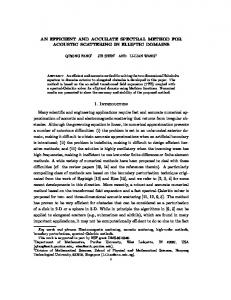
The experimental setup for our PolMux-MIMO system is shown in Fig. 1. Two 1.25 Gbps pseudorandom bit sequences (PRBS) with a bit length of 215 − 1 are generated from a
Ambigurity Removal
II. E XPERIMENTAL S ETUP
X-Branch
Y-Branch
PD 1
Decision and BER Test
Radio-over-fiber (RoF) technology provides a good solution to increase the coverage while maintaining the mobility of the broadband services in the local area network scenario. However, there are challenges when turning this technology into practice, including spectral efficiency, wavelength reuse, wireless channel capacity and components cost [1]. Polarization multiplexing (PolMux) is a promising technique to double the spectral efficiency by transmitting data in two orthogonal polarization modes within the same spectral range. [2]. Furthermore, wireless multiple-input multiple-output (MIMO) technique provides the possibility for bandwidth-limited systems to increase their channel capacity through spatial multiplexing [3]. For the wireless MIMO systems, channel estimation is essential for signal demodulation. Work has been done either using fixed antenna distances [4] or using trainingbased channel estimation [5]. However, strict synchronizations are required in these methods. In contrast, constant modulus algorithm (CMA) based equalizer is able to make blind estimation when transmitting constant envelope signals, e.g. QPSK [6]. Meanwhile, CMA could also treat the polarization rotation in the fiber together with the wireless crosstalk when combining the PolMux RoF system with MIMO technique. In this paper we experimentally demonstrate a PolMux-RoF system with a 2 × 2 MIMO wireless link. By using both PolMux and wireless MIMO, 5 Gbps QPSK signal at 5.4 GHz carrier radio frequency (RF) with spectral efficiency of 4 bit/s/Hz is successfully transmitted through a 10 km SMF plus up to 2 m wireless link. This is the highest wireless capacity reported at this carrier frequency to the best of our knowledge.
EDFA
τ
LNA 1
LNA 2
PD 2
PA 1
d
PA 2
DSP Based MIMO Receiver
Fig. 1. Experimental set-up (VSG: Vector signal generator; PBC/PBS: Polarization beam combiner/splitter; PA: Power amplifier; LNA: Low-noise amplifier)
pattern generator. These two data sequences are combined and modulated as in-phase and quadrature components at a vector signal generator (VSG) to generate a 2.5 Gbps electrical QPSK signal with 5.4 GHz carrier frequency. The signal is directly modulated on to the lightwave by using a vertical-cavity surface-emitting laser (VCSEL) at central wavelength 1550 nm. After a 3 dB power divider and by adding a delay in one branch, the signals at the two branches become uncorrelated, representing two independent RoF QPSK signals. The two signals are polarization multiplexed at a polarization beam combiner (PBC). The combined PolMux QPSK RoF signal with data rate of 5 Gbps is amplified by a booster Erbiumdoped fiber amplifier (EDFA)and transmitted over a 10 km single mode fiber (SMF). At the wireless access point (WAP), the received signal is aligned to a polarization beam splitter (PBS), which divides the PolMux signal back to X and Y polarization. The RF signals are then recovered by two photodiodes (PD) and fed to two transmitter antennas. The two pairs of transmitter and receiver antennas formed a 2 × 2 wireless MIMO system. The
296
1 Opt B2B 1m Wireless X Opt B2B 1m Wireless Y 10km SMF 1m Wireless X
-log(BER)
10km SMF 1m Wireless Y
2 FEC
2 dB
3 4 5 6 -22
-20
-18
-16
-14
-12
-10
Optical Power into PD (dBm)
(a)
Fig. 2. Received signals’ constellations of X and Y branches before (upper) and after (lower) CMA equalization)
1 10km SMF 1m Wireless 10km SMF 1.5m Wireless
separation between the two transmitter antennas is set to 1 meter, so as the separation between the receiver antennas. The two signals received by the receiver antennas are sampled by a 40 GSa/s digital anology converter (ADC) and demodulated by a digital signal processing (DSP) based MIMO receiver.
-log(BER)
10km SMF 2m Wireless
2 FEC
3
3 dB
4
III. R ESULTS
5
CMA equalizer, which has two input signals with crosstalk from each other, can lock each one component of the equalizer outputs on to each input. Therefore after equalization the crosstalk can be reduced or eliminated. The performance improvement is studied by comparing the received signal quality before and after the CMA processing. As shown in Fig. 2, after back-to-back (B2B) optical PolMux plus 1 m wireless MIMO transmission, the received signals’ constellations disseminated due to polarization rotation in optical links and the wireless crosstalk from neighboring transmitter antennas. In contrast, after the optimized CMA equalization, the constellations became much smoother and more compact. Fig. 3 (a) shows the bit-error rate (BER) as a function of received optical power by the PDs in optical B2B and after 10 km SMF, both with 1 m wireless distance between the transmitting and receiving antennas. Due to the slightly different responsivity of two PDs, the performances have around 0.5 dB penalty between the X and Y branches. Meanwhile, we can observe that there are around 2 dB penalties between 10 km SMF transmission and optical B2B. BER curves for different wireless distances (1 m, 2 m and 3 m) after fiber transmission are shown in Fig. 3 (b). In this figure the BER are calculated for the total 5 Gbps QPSK signals transmitted in both channels. It indicates that there is only 1 dB penalty between 1 m and 1.5 m wireless transmission, while 3 dB when the distance goes up to 2 m, This is because as the attenuation in the air becomes larger, the SNR at the receiver goes lower, so that the system turn to noise-limited,where CMA has limited equalization capability. Considering the FEC limit at a BER of 2 × 10⁻³ , it is clearly shown that in all measured distances we are able to achieve transmissions with BER well below this limit.
6 -20
-18
-16
-14
-12
-10
-8
-6
Optical power into PD (dBm)
(b) Fig. 3. (a) BER as a function of optical power into PD for optical B2B and 10 km SMF transmission, both with 1 m wireless MIMO; (b) BER curves for different wireless distances after 10 km SMF transmission
IV. C ONCLUSION We experimentally demonstrated a VCSEL-based RoF system by combining PolMux and wireless MIMO techniques to increase the spectral efficiency. A CMA-based digital equalizer was proposed to implement blind estimation of a wireless MIMO channel. In the experiment, a 2 m wireless and 10 km SMF transmission of 5.4 GHz QPSK with data rate up to 5 Gbps, and hence 4 bit/s/Hz spectral efficiency was successfully achieved. The performance improvement by the CMA equalizer in its supportable wireless distance makes our spectral efficient MIMO system an attractive solution for providing short range wireless services. R EFERENCES [1] L. Christina et al., paper OWP5, OFC/NFOEC’2009. [2] A. Sano et al., “Ultra-High Capacity WDM Transmission Using Spectrally-Efficient PDM 16-QAM Modulation and C- and Extended LBand Wideband Optical Amplification”, J. of Lightw. Tech., vol. 29, no.4, pp.578-586, Feb.15, 2011. [3] M. A. Jensen; J.W. Wallace, “A review of antennas and propagation for MIMO wireless communications”, IEEE Trans. on Antennas and Propagation, vol.52, no.11, pp.2810- 2824, Nov. 2004. [4] Shu-Hao Fan et al., paper Th.9.B.1, ECOC 2010. [5] T.H. Chang; Wei-Cheng Chiang; Y.-W.P. Hong; Chong-Yung Chi, “Training Sequence Design for Discriminatory Channel Estimation in Wireless MIMO Systems”, IEEE Transactions on Signal Processing , vol.58, no.12, pp.6223-6237, Dec. 2010. [6] P. Johannisson et al., paper Th.9.A.3 ECOC 2010
297