A straightforward graphical user interface for basic and advanced signal processing of thermographic infrared sequences Matthieu T. Klein, Clemente Ibarra-Castanedo, Xavier P. Maldague*, Abdelhakim Bendada Université Laval, Pav. Pouliot, Dpt. Gel-Gif, Local 1300, Quebec, QC, Canada, G1K 7P4 *
[email protected]; phone 1 418 656-2962; fax 1 418 656-3159; mivim.gel.ulaval.ca
ABSTRACT IR-View, is a free and open source Matlab software that was released in 1998 at the Computer Vision and Systems Laboratory (CVSL) at Université Laval, Canada, as an answer to many common and recurrent needs in Infrared thermography. IR-View has proven to be a useful tool at CVSL for the past 10 years. The software by itself and/or its concept and functions may be of interest for other laboratories and companies working in research in the IR NDT field. This article describes the functions and processing techniques integrated to IR-View, freely downloadable under the GNU license at http://mivim.gel.ulaval.ca. Demonstration of IR-View functionalities will also be done during the DSS08 SPIE Defense and Security Symposium. Keywords: Open source software for Matlab with GUI, Infrared image and sequence viewer, basic image processing, infrared thermography, contrast, Fourier transform, color map problem
1. INTRODUCTION A variety of basic functions such as displaying a sequence of infrared images, handling their color maps or locating regions of interests (ROIs) within an image or a sequence have been - and will remain the most fundamental tasks in active infrared thermography. They are costly in time because they are redundant to most of IR NDT experiences and applications. They are costly in terms of errors as inspections eventually rely on visual assessment of pre or post processed IR images. Curiously enough, both the supply and the demand of software products offering IR NDT processing functions is fairly low. 1.1 The needs of the two market segments for IR NDT image processing software People in marking defined a “market segment” as a subgroup of people or organizations sharing one or more characteristics that cause them to have similar needs [1]. Two market segments can be easily identified in IR NDT: the application segment and the research segment, both of them being niche i.e specialized segments. Users from the application segment are typically applying known methods of IR NDT. They are normally inspecting the same kind of specimen and they likely need to accomplish specific and precise scenarios repeatedly. For example, this segment may need performing a Fourier transform on 2 to 4 mm aircraft panels from an IR sequence that last 5.5 seconds and from which all defects that are grater than 10 cm2 must trigger an alarm. Once someone from this segment has defined his precise needs, he needs tools that are efficient but doesn’t need much more versatility. The second segment, the research segment, is different. It includes R&D people from the industry, educational or government sectors. These people mostly work on projects basis that are often changing. For instance someone from the research segment may use more than one camera, try various IR NDT methods, adjust or invent new processes of IR inspection. He may need software products that can handle a variety of image resolutions, various bits per pixel, various types of camera, various image processing algorithms and new methods to compare them to each other to find the best compromise. Thus, people from the research segment need extremely very flexible software tools. 1.2 Existing IR NDT software Infrared camera manufacturers sometimes provide more or less generic software applications for thermography analysis. Cedip provides its Altair-Li software an interesting IR NDT suite as a part of a whole system for IR NDT [4,5]. FLIR did some serious efforts as well to create the RTools package that also offers advanced measurement functions. Manufacturer’s software tools are only matching their own camera hardware and can hardly be customized although SDK’s are sometimes available. Termidge was one of the first independent and third party software application to
Thermosense XXX, edited by Vladimir P. Vavilov, Douglas D. Burleigh, Proc. of SPIE Vol. 6939, 693914, (2008) 0277-786X/08/$18 · doi: 10.1117/12.776781 Proc. of SPIE Vol. 6939 693914-1
accomplish a relatively complete image processing for IR NDT [6]. More recently Innovation Inc, a spin-off company of Tomsk Polytechnic University which mission is to develop a cutting-edge software used in IR thermographic NDT, created ThermoFitPro [11]. ThermoFitPro appears to be the most specialized and advanced tool for processing IR image sequences for IR NDT available as of January 2008. ThermoFitPro has also the advantage of being developed by people who actually work in IR NDT. The developers of this product also offer the possibility of developing custom functions. 1.3 High-level programming languages for the research segment regarding IR NDT tools Another category of software tools usually used in the IR NDT research segment are high-level programming languages that enable accomplishing specific tests on the fly and create small software applications. The term "high-level language" does not imply that the language is superior to low-level programming languages. "High-level language" refers to the higher level of abstraction from machine language. Rather than dealing with registers, memory addresses and call stacks, high-level languages deal with variables, arrays and complex arithmetic or Boolean expressions. Stereotypically, high-level languages make complex programming simpler, while low-level languages tend to produce more efficient code [7]. Application written with lower – level languages are faster, more efficient and thus appropriate for the application segment. LabVIEW from National Instrument is an example of a high-level language often used in IR NDT. FLIR managed to develop its RTools product with LabVIEW for general IR processing. Scilab [8,9] and Matlab are 2 other examples of high-level programming languages widely used in IR NDT research. Both languages have the advantage of running in a numerical computing environment. High-level languages such as Matlab from The MathWorks and Scilab from the Scilab Consortium are flexible enough to allow any kind of image and signal processing almost directly in their respective numerical environment. Both allow fast, yet advanced image processing and matrix computation. To some extend it is possible to create scripts and building customs programs with a graphical user interface within Matlab or Scilab. Those are languages only, which means using them offer an excellent flexibility, at the price of having to write command line code and functions which usually take much more time than using specialized applications as ThermoFitPro. The reason why high level languages are not much used by the application segment is that the users first need to create their own application under those languages. Applications created with high-level languages also tend to be slower than software applications created with lower level languages as ThermoFitPro. Furthermore, high-Level languages often need their own environment to run although Matlab’s scripts can be compiled – in fact Matlab’s scripts are still interpreted but packed with a micro kernel of Matlab. It is worth noting that high-level functions that are purely mathematical such as Fourier transforms, 2D or 3D filters and matrix operations are as fast in Matlab or Scilab as they would be in lower level programming languages such as C or C++. Matlab is known to have pushed out the limits of optimizations with matrix computations by using the Intel Integrated Performance Primitives library (IPP). IPP is a software library that exploits advanced hardware functions of matrix computation embedded in Intel and AMD CPU’s. IPP can be can used with any software applications, not only Matlab [2] as long as the application is designed to support it. Matlab also comes with independent toolboxes most of them being developed by third party companies and universities. Scilab can be seen as a simplified Matlab and has proven us to be a powerful alternative to Matlab. Scilab is a totally free and open source product with outstanding performances and functionalities. It uses a very similar syntax to Matlab. It is recommended to carefully evaluate all the various high level languages, which are not just limited to Scilab and Matlab, before investing in expensive high-level language licenses. High-level languages and specialized software applications created with lower level languages as ThermoFitPro, Altair-Li and so on, can perfectly be used in conjunction.
2. IR VIEW AS A MATLAB GRAPHICAL USER INTERFACE FOR IR NDT. 2.1 Principle Fundamental tasks in IR NDT include the ability to browse through IR sequences of images, adjusting the colorpalette, and computing the FFT. Whatever the projects the IR NDT research segment is working on, this segment always need to manipulate large IR NDT sequences of images. This can be accomplished under Scilab or Matlab by issuing various command line functions or scripts, which tends to get quite a repetitive, boring and time consuming task. IR View is a Matlab program with a graphical user’s interface handling IR sequences in a more convenient way while staying under a high level programming language environment. It may improve the productivity given the time the researchers are spending on post processing once the images are actually acquired.
Proc. of SPIE Vol. 6939 693914-2
A limitation of IR View (and Matlab) is the memory. That issue can be solved by using 64 bits machine and operating systems or by accessing smaller parts of the IR sequence and working on smaller regions of interest, or by changing the data format. Examples of formats that have been developed to solve memory issues are the Hierarchical Data Format (HDF4) developed by the National Center for Supercomputing Applications or the HDF-EOS developed by the National Aeronautics and Space Administration for storage of data returned from the Earth Observing System. The harder task in developing an interface such as IR View is not the code by itself, It is more about thinking what to do, not how to do it. The idea at LVSN was to develop a simple, compact and intuitive interface. During the past years, IR View’s users ultimately ranked the simplicity of the interface an important criterion. Another key is to make the tool as stable as possible. This is an extremely difficult task as it requires the developers to evaluate all the worst-case scenarios a user could fall in, especially those that are difficult to predict. Furthermore, another important criterion to succeed is to have a clear and up to date documentation embedded within the software application in addition of a contextual help as a form of bubbles that appears next to buttons or entry fields of the interface. IR View is also packed into a single Matlab script, to make it easier to copy, transfer and install. It has been noticed over the years that not respecting those basics criterions resulted in people not using the programs. IR View also exists as a C++ implementation with the exact same functionalities as the IR View version that runs on Matlab. The C++ version was created as an intent of having a faster processing power with less memory required. Although IR View’s C++ code is not specifically optimized it is still fairly good. Unfortunately, this interesting experiment has demonstrated that the C++ version of IR View was, at best, as fast as the Matlab version of IR View (if not slower) and used as much memory as Matlab. In addition, having an external application to Matlab or Scilab adds some constraint to exchange the data. Consequently the C++ version was put aside for the moment. Hopefully, more advanced optimizations to the C++ version could provide the tools for a more efficient program in the future. 2.2 The open source Approach According the Bruce Perens, an Open Source ™ software must cover precise points ranging from free redistribution, access to the source code, free personal and commercial usage [3]. The open source is a principle only. It doesn’t state any legal form. The legal part is rather defined in specific open source licenses. In 2008, the Open Source Initiative, a California public benefit corporation, counted 58 different recognized open source licenses. In the context of IR View, the GNU Lesser General Public License (L GPL) was though to be the most appropriate open source license. L-GPL allows using the software for free, analyzing it, changing its source code and redistributing it under generous conditions specified in the license. The most interesting principle in Open Source products is that the demanders are also quite often the suppliers. It means that those who code the software are usually the same who use it. It is an advantage as there are greater chances that the produced software matches more adequately people’s needs. In general in the commercial market, software suppliers or software coders are not the demanders. The supplier only creates a software application as close as possible to what he thinks the demanders are looking for. This is the reason why Open Source products are often and high quality products.
3. OVERVIEW OF THE FUNCTIONS OF IR VIEW 3.1 Functions IR View displays the IR images with a graphical interface from an numerical array given as an argument to the program e.g: ir_view(my_array). The array is either a 2D matrix of size MxN thus containing 1 frame/image or a 3D matrix of size MxNxI containing I frames. The array can be of any type of data such as double, uint8 or uint16. IR View can also accept a filename of a multi-framed *.TIF file as an argument. For instance, files recorded from the FLIR / Indigo Micron A10 Camera can be loaded as ir_view('mysequence.tif'); IR View functions are: Adapting the color scale to the minimum and maximum value of the current frame or of a region of interest; Adjusting with precision the color limit mapped to any range of temperature (or any other pixel value such as gray level, phase or amplitude); Computing the 2D phase and amplitude of the Fourier transform; Helping to find the Extrapolated Contrast parameters and computing the corresponding Contrast; Applying a 2D Gaussian filter on IR Images; Changing the type of colorpalette; Extracting the current frame as displayed to Matlab's workspace; Plotting the temperature evolution versus the time for any given point [x,y] of the sequence of images; Computing the Correlated image of a pulsed thermography sequence.
Proc. of SPIE Vol. 6939 693914-3
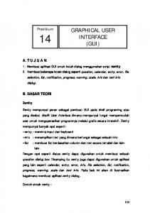
3.2 Details of the graphical user interface IR View always shows a resizable display window and a control panel. The display window shows the current frame as determined in the control window. The Control Panel contains 4 sections. .jFigure 3: Control Panel
p.gure 1: IR View 1.1.3 - mivim.gel. uluvul.cu - Dispi... FOe
Edit
20 40
ktev
e & — — '— r-. —
!
insert bole Desktop Windov Help
EiiiiiiEIEiiiiii!iiii 16 ,— -— ——.—
4
13.6
IF View 1 .7.3 - mivim .gel .uIeveI .ce
60
IOU
ISO
SetROl Te±LabeI FT Phase Corral CT Reset ROl E±ract Img IjPoCEraPCTSetuPCT
Ext
Coetrolling fig I & 2
Fig. 1. Left: the display window. Right: the control panel of IR View
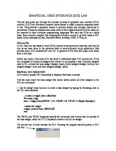
-1 Figure?: [xlrapolated Contrast Setup and Temperature Profile utilities
e & — Lre't ThcS eStcp ,dccq (remperature KD vs. (time t) in hi-log space
ID
IOU
Iiew1.7.3mivim.gel.uleYel.cemm ID
CI
mdcl Time (gross+fine cursors): 1 .224
Norm.
LogSp.
Oiffusivty (gross+fine cursors): 0.129 mm'2Is E±repoIetion elgorthm:
•1 C Grid
I E± .Lines
Fremes II Legend
Auto Cleer
Sleb (wth losses)
L (plate width): 3.41 mm Losses: 10.2
fl!_ __
V
Conductivty (gross+fine curs.): 0.162 m*K)
F-
Fig. 2. Extrapolated contrast setup window. This also plots the temperature versus time of a given point.
The first section of the control panel is the Display Control. The cursor is intended to select the frame to be displayed within an IR sequence. Three checkboxes allow inverting the axis along X, Y or Z. Flipping the axis along Z of an image is relevant when the image is displayed as a 3 dimensional image only, the value of each pixel being mapped to the Z axis. The Axis and Grid checkboxes are toggling the axis and a grid on and off to help locating features on the image. The Norm checkbox forces the Display Window to show a normalized image where pixels are squared. This links the X and Y axis when resizing the Display Window. The 3D View button lets the user changing from a planar view to a 3D view. This 3D feature is different from the standard 3D button available on the figure’s toolbar of Matlab. The grayed
Proc. of SPIE Vol. 6939 693914-4
out list under the 3D View button represent the 3D options and 3D rendering available when the 3D mode is activated. For example the transparency option can be activated from this list. The transparency is a great way to see the hidden areas in the 3D mode. The second section of the control panel is the 2D Filter. Although it is called 2D it also works when displaying a 3 dimensional view of an image. The 2D filter actually means the image is spatially filtered on X and Y. It is not filtered in time from one frame to the other. The filter is a 2D convolution between the current image and a Gaussian kernel. The Gaussian filter is a natural filter that fits almost any type of IR image. For example the Gaussian filter can properly cope with regular patterns such as those observed at the surface of composite materials. Instead, an averaging window would damage images with regular patterns because of the bad frequency response of standard averaging filters. The third section is the Color Management section that is one of the most important features. New IR thermography users often tend to under evaluate the need for precise colorpalette adjustments. This is especially true as IR images are intensity images sampled way beyond the traditional 8 bits per pixel. The drop list in the Color Management section box gives various predefined Matlab’s colormaps such as the standard NCSA Fluid Jet, the Linear Gray Scale and so on. In the most recent version of Matlab, the colormaps can be toggled on and off and directly adjusted from the standard toolbar of any Matlab’s figure. The Color Slider simply sets the number of colors that should be displayed. Displaying only 2 colors is a good way to quickly segment image features by mean of a simple threshold value as shown in Fig 6. The two Color Limit cursors set the lower and upper values between which the colorpalette must fit in. The Lock checkbox is function that locks the Color Limit cursors. When locked the 2 cursors are linked to each other and moving either ones will force the other cursor moving of the same displacement. In other words the Color Limit High or Low can be changed with the Lock function on, so that Color Limit High – Color Limit Low remains a constant value. This allows a fine color scanning that can be seen as a zoom in the color space to detect small variations of temperature. This is useful when a defect is known to bring a small variation of temperature in an image that shows relatively big temperature changes, especially because of non-uniform heating. The Fit Image buttons adjusts the colorpalette limits to the minimum and maximum value of the current image or its region of interest if any. The Fit Sequence button does the same but search for the min and max values in the whole sequence instead of searching in the current image. This mode is needed when comparing one image to the other with the same colorpalette reference. Applying the 2D Gaussian filtering will often prevent misbehaving or dead pixels from biasing the limits found by the Fit Image button – which explain why the colorpalette often gets better when a filter is active. The forth and last section involves 3 types of basic processing, which are the FFT in both phase and amplitude modes, the extrapolated contrasts and the correlated contrast [10]. The Region of Interest buttons (ROI) are intended to select a smaller area of the image that restricts the search of the min and max value returned by the FIT Img and FIT Seq buttons. The ROI is usually used to map a full colorpalette range within a small region of interest in order to enhance the colors in this region. The Extract button simply extracts the current frame or all the frames of the sequence in Matlab’s environment in accordance with the ROI, the filter and the image processing (FFT, Contrast) applied.
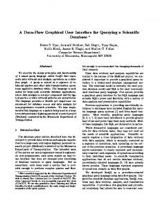
4. SOME EXAMPLES The following images are computed and displayed with IR View, from a test sample in pulsed thermography as an example. A total of 6 defects (flat bottom holes) with increasing deepness on a Plexiglass specimen can be seen. The colorbar shows the temperature increase in degrees for the thermograms. It is in radians for the phase images and represents the correlation coefficient for the correlation image.
Proc. of SPIE Vol. 6939 693914-5
5.6
5.6
25 4.6
4.6
645
43.6
65
3.6
3-
3
2-
2.6
85
2.6
2 1.5
1.6
ISO
5.6
120
20
40
65
85
lOS
120
140
26
ISO
165
123
IR'/i1 .7.3
Fig. 3. Left: a simple temperature image. Right: same view in 3D with a transparent texture
6.6
2.9 2.89
2.8 4.6 2.78
2.7 3.6
2.88
2.8 2.88
2.6 1U
8U
IR'/i1 .7.3
IR'/i1 .7.3
Fig. 4. ROI’s selected at 2 different places. Because the colormap is redistributed within the ROI, it allows detecting small variations of temperature. For instance the default shown in the ROI box in the right figure is hardly visible when the colormap is distributed over the whole image as it is the case in the previous figures.
I
•
S
J.9 J.8
•oo
J.7
0.66 0.6
0.46 0.4
J.8
0.36
I
J.8
S
S J.4
0.26
J.3
'/i1.7A 20
0.2
J.2
View 1 .7.4 - mivim .gel .uIavaI .ca
40
80
80
100
120
140
0.3
180
Proc. of SPIE Vol. 6939 693914-6
Fig. 5. Left: raw correlation image without any filter. Right: same raw correlation image with a Gaussian filter applied with a variance of 0.85 pixels. In both image the colorpalette is automatically adjusted to the minimum and maximum of the image. The colorpalette limits of the non smoothed image on the left are obviously biased because of one or a few misbehaving pixels. Those pixels are suppressed when the image is smoothed which explain why the colorpalette look better on the smoothed image.
3.84 3.83 3.82 3.81
3.8 3.89 3.88 3.87 3.88 3.88 3.84
20
00
40
IR'/i1 .7.3
IR'/i1 .7.3
120
Fig. 6. Left: the ‘lock’ colormap was applied to help finding the 3.59oC degree limit. This is the best threshold that allows showing the 3 upper defects while hiding the background. The colorpalette was then changed to 2 colors in grayscale mode with a Gaussian filter. This gives a convenient binary image that is easier to process for automatic defect recognitions, or when a go / no-go decision has to be made. This image was then extracted from IR View, transformed as a binary mask and multiplied by its corresponding temperature image. This gives the figure shown in 3D on the right.
2.86
0.00
0.0
2.8
0.40 2.76
0.4 0.30
2.7
0.3 2.66 0.20
02
2.6
20
IR'/i1 .7.3
20
4U
80
IR'/i1 .7.3
Fig. 7. Left: An phase FFT image. FFT images can be computed within a ROI to save memory and time. This is useful when working on very large sequences. Right: A correlated contrast Image
Proc. of SPIE Vol. 6939 693914-7
0.8 0.8
1.8
1.4
0.4 1.2
0.3 0.2 0.1
0.8
U
0.8 -0.1
10
-0.2
0.4
-0.3
0.2
50
IR'/i1 .7.3
Fig. 8. Left: Extrapolated contrast image. Right: maximum contrast image showing the maximum contrast reached at any time during the whole acquisition. This image is obtained by extracting the whole sequence of contrast images with IR View into Matlab’s workspace and by applying a Matlab function to search for the maximum values along the 3rd dimension.
5. CONCLUSION Software tools are part of assets among hardware and human resource to work in IR NDT research. They are costly from 3 different points of view. The first reason is that they are costly when the needs are not properly defined, which results in organization ordering or creating software that will never be used. This is caused by developers not clearly understanding the environment in which researchers are working, and because of researchers are unable to properly explain and define their own needs. Ordering custom software is a very difficult task, which is even underestimated by IR NDT experts. The second reason why software products are costly is because of maintenance needed. Cameras change, needs change, so do software that must follow. The third and last reason of the hidden cost of software tools is the extensive use of inappropriate tools which create non-optimal results, sometimes for years. Given the cost invested in hardware and human resources to obtain IR NDT results, one can’t afford having non optimal results simply because the software doesn’t suit the needs. This paper is intended to recall the importance of correctly evaluating the software needs. IR View is not a universal tool that will solve all IR NDT problems. It is only a personal solution to our personal needs at LVSN, which are believed to be similar enough to those of other organizations. This paper may incite research teams to have a clearer vision regarding their software strategies or share their methods of working through other publications. IR View can be used by everybody within the scope of the L-GPL license. It is freely available at www.gel.ulaval.ca. References to IR View are encouraged but not required when used.
REFERENCES 1
Day, G. "Strategic Market Analysis: Top-down and bottom-up approaches", working paper #80-105, Marketing Science Institute, Cambridge, Mass. 1980. 2 Stewart Taylor, "Intel Integrated Performance Primitives: How to Optimize Software Applications Using Intel IPP," ISBN 978-0971786134, Intel Press; Pap/Cdr edition (April 2004). 3 Bruce Perens, “The Open Source Definition”, Linux Gazette issue 26, dated February 10, 1998. 4 R. Jones and S. Pittb, using Altair-li in "An experimental evaluation of crack face energy dissipation," International Journal of Fatigue Volume 28, Issue 12, December 2006, Pages 1716-1724 5 F. Escourbiac, S. Constans, X. Courtois, A. Durocher, using Altair-li in "Application of lock-in thermography non destructive technique to CFC armoured plasma facing components", Journal of Nuclear Materials 367–370 (2007) 1492– 1496
Proc. of SPIE Vol. 6939 693914-8
6
Vavilov V.P, Kourtenkov D., Grinzato E., Bison P., Marinetti S., Bressan C., Inversion of Experimental Data and Thermal Tomography Using „Thermo Heat” and „Termidge” Software, Proc. QIRT’94, p. 273-278, 1994, 7 Wikipedia US, definition of “High-level programming language,” http://en.wikipedia.org/wiki/Highlevel_programming_language as consulted on Jan. 2008 8 A.S. Duarte, J.H. Santos, H. Fernandes, A. Neto, T. Pereira, C.A.F. Varandas, using Scilab in "FireCalc: An XMLbased framework for distributed data analysis", Fusion Engineering and Design, 2007 9 Scilab and Scilab consortium, http://www.scilab.org 10 Matthieu Klein, Clemente Ibarra-Castanedo, Abdelhakim Bendada, Xavier Maldague, "Thermographic signal processing through correlation operators in pulsed thermography," SPIE Proc. Thermosense 30th (SPIE: Society of Photo-Optical Instrumentation Engineers), Orlando, 2008 11 Software ThermoFitPro, from Innovation Inc. http://www.innovation.tomsk.ru/ind_en.html
Proc. of SPIE Vol. 6939 693914-9