Jun 10, 1996 - cution of redundant disk array operations, including recovery from errors, .... the graph to return a pass/fail status with âfailâ implying that a hard error was ... If the engine detects a failed node in a DAG after it has executed the ...
A Structured Approach to Redundant Disk Array Implementation *William V. Courtright II, Garth Gibson, *Mark Holland, Jim Zelenka 10 June 1996 CMU-CS-96-137
School of Computer Science Carnegie Mellon University Pittsburgh, PA 15213 *Department of Electrical and Computer Engineering Carnegie Mellon University, 5000 Forbes Avenue, Pittsburgh, PA Appears in the Proceedings of the International Computer Performance and Dependability Symposium (IPDS), Sept. 4-6, 1996.
Abstract Error recovery in redundant disk arrays is typically performed in an ad hoc fashion, requiring architecture-specifi c code which limits extensibility and is difficult to verify. In this paper, we describe a technique for automating the execution of redundant disk array operations, including recovery from errors, independent of array architecture. Our approach employs a graphical representation of array operations and a two-phase error-recovery scheme we refer to as roll-away error recovery. We demonstrate the validity of this approach in RAIDframe, a prototyping framework that separates architectural policy from execution mechanism. RAIDframe facilitates rapid prototyping of new RAID architectures by localizing modifications. In addition, RAIDframe-implemented architectures run the same code when configured as an event-driven simulator, a user-level application managing raw disks, and as a Digital Unix device-driver capable of mounting a filesystem. Evaluation shows that RAIDframe performance is equivalent to less complex array implementations and that case studies of RAID levels 0, 1, 4, 5, 6, and parity declustering achieve expected performance.
This work was supported in part by Data General, DEC, EMC, Hewlett-Packard, IBM, Seagate, Storage Technology, and Symbios Logic. IBM and Symbios Logic provided student fellowships. CMU’s Data Storage Systems Center also provided funding from the National Science Foundation under grant number ECD-8907068. The views and conclusions contained in this document are those of the authors and should not be interpreted as representing the official policies, either expressed or implied, of sponsoring companies, agencies or the U.S. government.
Keywords: disk array, storage, architecture, simulation, directed acyclic graph, software.
1. Introduction Disk arrays are an effective method of increasing I/O system performance [Salem86, Kim86]. By incorporating redundancy into arrays, systems are able to survive disk faults without loss of data or interruption of service [Lawlor81, Patterson88, Gibson93]. Popularized by the RAID taxonomy and driven by a broad spectrum of application demands for performance, dependability, capacity, and cost, a significant number of redundant disk architectures have been proposed. These include designs for emphasizing improved write performance [Menon92, Mogi94, Polyzois93, Solworth91, Stodolsky94], array controller design and organization [Cao94, Drapeau94, Menon93], multiple fault tolerance [ATC90, Blaum94, STC94], performance in the presence of failure [Holland92, Muntz90], and network-based RAID [Hartman93, Long94]. Finally, the importance of redundant disk arrays is evidenced by their pronounced growth in revenue, projected to exceed $9 billion this year and to surpass $13 billion in 1998. Architects currently evaluate novel disk array architectures using back-of-the-envelope analytical models and simulation experiments [Chen90a, Lee91]. In our experience, the specification and implementation of a detailed array simulator, even if it does not closely model a running system, is an arduous task. As an example of the complexity involved in modifying a simulator, we examined simulator code changes we made in the development of our first new array architecture [Holland92]. We began with raidSim, a 92 file, 13,886 line detailed array simulator derived at Berkeley from an implementation of a functional device driver in the Sprite operating system [Chen90a, Lee91]. To this simulator we added new array functions, replaced previously unessential simple mechanisms, and augmented statistics recording, workload generation, and debugging functions. During these changes one file was deleted, 11 files with 1,204 lines of code were added and 46 files were modified, changing 1,167 lines and adding 2,742 lines. Collectively, to do the research reported in one paper, the number of simulator lines added or changed, 5,113, was equivalent to 36% of the size of the original simulator and affected half of raidSim’s modules. With this development cost in mind, we set out in 1994 to construct an array evaluation system that reduced the cost and complexity of experimenting with new array architectures. We advocate a graphical programming abstraction for use in redundant disk array development [Courtright94]. Given this structured representation, we are able to eliminate the need for architecture-specific error recovery code using an technique we refer to as roll-away error recovery. Representing RAID operations as directed acyclic graphs (DAGs), and using a simple state machine capable of executing operations represented as DAGs, we have constructed RAIDframe, a rapid prototyping framework for redundant disk arrays [Courtright96]. RAIDframe is designed to allow new array architectures to be implemented with small, localized changes to existing code. Architecture features that cannot be expressed in request DAGs are usually satisfied by RAIDframe’s flexible, dynamic address mapping mechanism, or its extensible disk queueing policies, although some changes, such as new redundancy computations, may require the definition of new DAG nodes. RAIDframe allows a single implementation to be evaluated in three distinct environments. First, it provides a discrete event simulator with configurable array parameters and disk models. To exercise this simulator, RAIDframe offers a synthetic and trace-driven load generator. Second, RAIDframe implementations and its load generator can be executed in a user process using the UNIX “raw” device interface to access real disks instead of simulated disk models. Finally, to allow real applica-
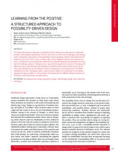
tions to be run against a file system mounted on a RAIDframe-described array architecture, the same implementation code that runs in simulation or as a user process can be run as a device driver in the Digital UNIX operating system on Alpha workstations. This paper begins with a description of our approach for representing and executing redundant disk array operations. Next, we describe RAIDframe which is based upon our approach. The paper is concluded with case studies of six array architectures, examining RAIDframe’s extensibility and accuracy. 2. Approach 2.1 Modeling array operations as DAGs Our development of an access sequencing abstraction owes much to prior storage systems. A powerful approach for localizing access-specific control is suggested by IBM’s channel command words and channel programs [Brown72]. Although this model serializes accesses, its success indicates that the range of primitives needed to support storage control is small and may directly correspond to operations provided by lower level devices. Similar abstractions are found in SCSI chip control scripts [NCR91] and network-RAID node-to-node data transfers [Long94]. A more flexible example of a storage control abstraction specifically developed for RAID architectures is the parallel state table approach in TickerTAIP, a distributed implementation of RAID level 5 [Cao94]. Our approach expands on the example of TickerTAIP, simplifying the expression of potentially concurrent orderings of operations by employing directed acyclic graphs (DAGs) of primitive actions [Courtright94]. We believe that a graphical abstraction has the added benefit of compactly and visually conveying the essential ordering aspects of a RAID architecture. Using DAGs to model RAID operations has a number of additional advantages. First, DAGs can be compactly represented in isolation from the engine that interprets and executes them. This localizes and delineates the code modified to experiment with RAID architectures. Second, because DAGs represent RAID architectures as well-defined connections of primitive actions, it should be possible to apply well-known verification techniques such as model checking [Clarke94] to demonstrate the correctness of an implementation. Third, the structural simplicity of DAGs provides RAIDframe with the opportunity to automate the handling of error conditions; that is, respond correctly to errors without regard to the RAID architecture implemented by the system. Figure 1 illustrates the DAG representation of five popular redundant disk array operations. The nodes represent actions such as disk read “R” or bit-wise exclusive-or “XOR”. The “NOP” nodes are used to ensure that each DAG has a single source and sink. The “C” node represents the location of a commit barrier, later described in Section 2.2. The arcs represent either data or control dependencies and constrain the ordering of execution of the nodes. 2.2 DAG execution and roll-away error recovery DAGs are executed using an engine which traverses a DAG from head to tail, executing each node after all of its parents have successfully completed. Executing DAGs in the absence of errors is trivial; however, recovering from errors which occur during the middle of execution can be challenging. Tra-
fault-free read
fault-free small write
fault-free large write
NOP
NOP
NOP
Rd
Rd
Rd
C
Wd
Rd
Rud
Rp
Rud
XOR
XOR
C
C
Wd
Wp
Wd
Wp
NOP
Rud
Wd
NOP
degraded-mode read
parity-failed degraded-mode write
NOP
C
Rud Rp XOR
Rd
Rd
Wd
Wd NOP
C Figure 1: DAGs which represent common operations in RAID levels 0, 4 and 5
ditional forward error recovery approaches would require a complete case-by-case analysis of all error scenarios, severely limiting rapid code extension to new architectures. Backward error recovery techniques used in transaction processing applications are able to provide a generalized error recovery mechanism which eliminates the need for case-by-case analysis, but introduce logging penalties. We employ a hybrid approach which eliminates the need for case-by-case error analysis and does not incur logging penalties. First, we isolate action-specific error recovery from graph-level recovery by requiring all nodes in the graph to return a pass/fail status with “fail” implying that a hard error was detected and “pass” implying the absence of errors or the detection and recovery from a soft error (e.g. a recovered media error in a disk read). Second, we isolate the processes of codeword creation and writing new parity stripe to disk by inserting a commit point node into the graph (“C” nodes in Figure 1). If the engine detects a failed node prior to the executing the commit point node, the engine suspends forward execution and works
User Request Map Access/Lock Select DAG Good Bad Execute DAG Good Bad
Access Failed Update Mapping
Free DAG/Unlock Access Complete Figure 2: Structured control flow
backward through the graph, undoing effects of actions which have already completed. Unlike database abort, this backward recovery does not necessarily fail the request. Instead, once the rollback is complete, and the device failure is reflected in the array state, RAIDframe selects a new DAG for executing the rolled-back operation in the array’s new state. If the engine detects a failed node in a DAG after it has executed the commit point node, it will role the graph forward to completion. Graphs which rolled forward successfully update all surviving disks. Logging is only required for nodes which precede the commit point; because these nodes are easily undone, the work required to perform the logging is trivial. Figure 2 illustrates how this process is used to create a comprehensive mechanism for processing user requests. Incoming requests are first mapped to physical disk locations and the necessary locks are acquired to ensure atomic parity updates. Next, the appropriate DAG is selected, given the request type and mapping information (which contains the location of any failed disks). If a DAG can not be selected, (e.g. too many disks have failed) the request fails. 3. RAIDframe: rapid prototyping for arrays To facilitate rapid development and experimentation with advanced array architectures, we developed a prototyping framework called RAIDframe. Driven by the fundamental decision that a modular architecture can greatly simplify the task of extending existing implementations to support new array architectures, RAIDframe isolates mapping, operation algorithms, sequencing, and device-specific actions. Coupled with the approach described in Section 2, architecture-specific code normally required for error recovery has been eliminated. Together, implementors are able to create new architectures in RAIDframe with only minimal changes which are localized.
3.1 Internal architecture RAIDframe provides extensibility through separation of architectural policy from execution mechanism. Policy, such as redundancy-update sequences and data layout, which varies with RAID architecture, has been isolated from infrastructure, code which does not change with RAID architecture. The primary infrastructure module is the DAG execution engine. This engine is responsible only for fully exploiting the allowable concurrency within a DAG; that is, the engine has no knowledge of the architecture embodied in the DAG. The engine is able to execute multiple DAGs concurrently. The policies available for implementing a particular array architecture are partitioned into a set of modules which may be independently modified: •
mapping: This module contains the layout routines which determine the placement of data and redundancy information in the array. The routines convert logical (user) addresses into physical (disk) addresses and identify associated stripe boundaries and redundancy units. The routines are typically short (5 lines of C code).
•
DAG selection: A “DAG selection” algorithm is required for each architecture. This algorithm, implemented as a C routine, determines which graph from the DAG library is to be used to execute a specific user request (type, layout map), given the current state of the array.
•
DAG library: This library contains the routines, such as CreateSmallWriteDAG(), which are capable of creating graphs if called by graph selection. Each routine receives type and physical mapping information and returns a pointer to a graph which is tailored for that request. Adding new graphs requires installing new or extending existing creation functions.
•
primitives: These are the functions which abstract the actions (e.g. XOR, DISKRD, etc.) from which DAGs are created. Primitives delineate the failure domains that RAIDframe accommodates; that is, when an action fails, the device associated with it is considered failed as well. Primitives are required to independently detect and recover from soft errors.
•
disk queue module: RAIDframe allows the disk queue management routines (written in C) to be extended. It assumes only a general queueing interface (enqueue, dequeue). RAIDframe currently supports FIFO, SSTF, and CVSCAN queueing policies.
•
disk geometry database: This database contains disk specifications used by the simulator. These specifications include layout parameters (tracks per cylinder, number of zones, etc.) as well as performance parameters (rpm, seek times, etc.).
3.2 Multiple evaluation environments Array architectures implemented in RAIDframe can be evaluated in three distinct execution environments: an event-driven simulator, a stand-alone application controlling UNIX “raw” disks, and a Digital UNIX device driver capable of mounting a standard file system on a set of disks. In all three environments, the code unique to a disk array architecture (mapping, DAGs, primitive operations, and
disk queueing) is reused without change. This multiplicity of evaluation alternatives provides considerable value to an array developer. Simulation allows modeling of unavailable hardware and rapid evaluation of traces. Because the same code, loaded in-kernel, can support a file system in a production operating system, a designer can be confident that simulation is not based on unrealistic abstractions. The in-kernel implementation additionally allows direct benchmarking of real applications (up to the CPU limitations imposed by RAIDframe’s software computation of parity). While the out-of-kernel RAIDframe execution environment is a performance compromise in the spirit of microkernel operating system design [Accetta86], experiments run at the user-level on attached but unmounted disks execute with little or no dependence on the local operating system. User level execution also offers accurate modeling, by direct execution, of the interactions between application threads and system scheduling [Ganger93]. Relative to an in-kernel implementation, however, user-level RAIDframe has decreased responsiveness to asynchronous events like disk completion and added messaging, system call, and context switching overheads. However, as Section 4.4 shows, this has little bearing on effective performance. Finally, both the user and kernel implementations have the advantage over the simulator that the correctness of implementations with respect to the proper maintenance of data and redundancy information is possible (the simulator does not move or store user data). Therefore, we have established the practice of developing new architecture in the user environment where we can easily establish their correctness, and then studying them in either the kernel or simulator environments. 3.3 Reconstruction Reconstruction of lost data is implemented in RAIDframe using a disk-oriented algorithm [Holland94]. A single reconstruction thread executes in parallel with the RAID execution engine. When invoked, this reconstruction thread issues, through the locking and DAG layers, a low-priority read request for the next unit on each disk required for reconstruction. As each reconstruct read completes, its data is XOR’d into the accumulating “sum” for the indicated stripe, and the next read request for that disk is issued. When the last unit associated with a particular stripe has been read and summed, the reconstruction thread issues a low-priority request for the now reconstructed data to be written to a replacement or spare disk. This algorithm allows reconstruction to keep one low-priority disk request in the queue for each physical disk at all times, maximizing the efficiency of reconstruction without significantly penalizing user responsiveness. 3.4 Utilities RAIDframe has both a synthetic workload generator as well as a trace-playback mechanism. The workload generator conforms its load to a script containing a variable number of access profiles with individual occurrence probabilities. Each profile defines a deterministic or exponentially distributed access size with a given mean and alignment. Access addresses are randomly generated throughout the entire address space, or with a given probability, within a single locality specified with each profile. Access types are either read, write, or sequential (the same as the last access with its address advanced).
Turbochannel
150 MHz Alpha CPU
FWD SCSI FWD SCSI FWD SCSI FWD SCSI FWD SCSI
FWD↔FSE FWD↔FSE FWD↔FSE FWD↔FSE FWD↔FSE
Figure 3: Test system
Traces understood by RAIDframe contain an explicit sequence of tuples: (thread ID, delay time before issuing this request, read or write, block address, number of blocks, and a blocking/non-blocking flag). To automate validation of new architectures, RAIDframe includes a variety of tests for validating read and write operations to arrays which are either fault-free, degraded, or undergoing reconstruction. 4. Case studies In this section we present six array architectures implemented in RAIDframe. A full description of these architectures is beyond the scope of this paper, but excellent tutorials are widely available [Chen94, Holland94, RAB96]. 4.1 Setup, configuration, and workloads Figure 3 illustrates our hardware environment. The host system is a 150 MHz DEC 3000/500 running Digital UNIX version 3.2, and has five DEC KZTSA fast-wide-differential SCSI adapters on its 100 MB/s Turbochannel bus. These adapters connect to five shelves of disks in a DEC StorageWorks 800 cabinet. Each shelf contains a DEC DWZZA fast-wide-differential to fast single-ended SCSI converter, and three one-gigabyte Hewlett-Packard model 2247 disk drives. In our evaluations, we use a single parity group consisting of ten disks on five busses, neglecting the dependent failure mode that would occur should a SCSI bus controller fail [Gibson93]. For all experiments, we used SSTF disk queuing and allowed RAIDframe to dispatch up to five outstanding requests to each disk drive. Furthermore, we configured RAIDframe to stripe on 32 KB units. RAID level 1 employed shortest-queue scheduling for selecting which copy (primary or mirror) would be read. Parity declustering used a logical array size of five disks distributed over the ten disk array.
60
Kernel Process - Real Disks
Kernel Process - Real Disks 300 Response time (ms)
Response time (ms)
50 40 30 20
200
100
10 00
200 400 600 Throughput (IO/sec)
800
00
200 400 600 Throughput (IO/sec)
800
Data was collected using RAIDframe’s trace-driven workload generator. This allowed us to apply identical, high-concurrency access sequences to each architecture executing in the simulation, userlevel, and device driver environments. We constructed trace files which are broadly familiar to readers of RAID related papers: random small accesses all of the same type [Patterson88, Chen90a, Chen90b, Muntz90, Holland92]. Specifically, our tests use 1, 2, 5, 10, 15, 20, 30, and 40 threads to issue blocking 4 KB operations on random 4 KB aligned addresses with no intervening delay. We show results for 100% reads and 100% writes separately. All results display the average of three experiment runs, each with a distinct seed. 4.2 Extensibility Our experience with adding new architectures to RAIDframe has shown that code reuse is high and that changes are densely clustered. The baseline implementation of RAIDframe, which includes RAID level 0 and all supporting utilities, is 34,311 lines of C code. Individually adding the remaining five architectures described in this paper required, on average, the addition of 3.6 new files and 1,049 lines of code per architecture, and virtually no changes to existing code. This results in an average code reuse of 97.3%. For example, the overall effort to implement RAID level 1 required 460 minutes during which 370 lines of code were produced or modified. Broken down, the time until first compilation attempt was 90 minutes, with first successful compilation 15 minutes later. Read DAGs first ran 55 minutes later, write DAGs 105 minutes later, read scheduling was implemented after 145 minutes more and degraded mode was operational in an additional 50 minutes. Similar times were recorded for implementations of interleaved [Teradata85] and chained [Hsiao90] declustering. The overall effort to implement interleaved and chained declustering required little over 240 min for each architecture. In each case, two thirds of the time was spent coding and a third debugging. Happily, these times represent the ability of an individual programmer unfamiliar with RAIDframe’s internal architecture, and therefore further reinforce our belief that RAIDframe is easily extended. Unfortunately, space considerations do not permit a discussion of interleaved and chained declustering performance.
500 RAIDframe, RD RAIDframe, WR Striper, RD Striper, WR
Response time (ms)
400
300
200
100
050
55
60 65 70 75 80 Throughput (IO/sec)
85
90
Figure 4: Relative single disk performance
4.3 RAIDframe efficiency Although RAIDframe is structured as an engine that interprets architectural specifications to implement an array, its structure does not substantially impede the performance of its accesses. To evaluate the overhead involved in RAIDframe, we compared its in-kernel RAID level 0 implementation to a simpler pseudo-device disk striper. This striper was developed independently, based on code from 4.4BSD-Lite, to provide high performance access for a file system research project [Patterson95]. We first consider its simplest configuration—managing a single disk. Figure 4 shows the negligible difference in disk throughput and average access response time for our microbenchmark set running against a single disk. While no difference is apparent in I/O performance, RAIDframe is consuming more of the host machine’s CPU cycles; the striper consumes 2.9–4.6% of the host CPU while RAIDframe consumes 4.2–6.7%. The discontinuity observed at the fourth data point occurs when the number of requesting threads exceeds the configured disk queue depth, causing both RAIDframe and the striping driver, to begin queueing disk accesses internally. Next we consider the impact of RAIDframe’s higher demand for CPU cycles on its performance in larger arrays. Figure 5 shows both CPU utilization versus number of disks and the resulting total throughput versus average response time when five user threads execute our microbenchmarks concurrently. RAIDframe’s computational overhead for RAID level 0 (no parity computations) causes it to consume 50% more processor cycles than the striper at all loads. However, this heavier computational load does not substantially reduce RAIDframe’s ability to exercise an array efficiently. 4.4 Microbenchmark case studies In this section we report measurements from simulation, user-level, and in-kernel RAIDframe. Because most of these case study architectures are well known, so is their relative performance. Specifically, based on the simple performance model given by Patterson, Gibson and Katz [Patterson88], we expect small, fault-free read accesses to achieve the same performance in all architectures except
100
100 Striper, RD RAIDframe, RD Striper, WR RAIDframe, WR
80 Response time (ms)
CPU utilization (%)
80
60
40
40
20
20
00
60
1
2
3
4 5 6 7 8 number of disks
CPU Consumption
9 10 11
00
200 400 600 Throughput (IO/sec)
800
Performance as a Function of Array Size
Figure 5: RAID level 0 performance of RAIDframe and striping driver
RAID level 1, whose shortest queue discipline should improve throughput and decrease response time [Chen90b, Bitton88]. For fault-free small writes, we expect minimum average response time for the parity-based architectures to be about twice that of the direct write architectures (RAID levels 0 and 1). Moreover, in an array of ten disks, we expect the small-write throughput of each architecture, compared to the throughput of a single disk, to be: 10x (RAID level 0), 5x (RAID level 1), 1x (RAID level 4), 2.5x (RAID level 5, parity declustering), 1.67x (RAID level 6) [Patterson88]. Figure 6 shows that the request throughput versus average request response time for our microbenchmarks in the simulator, user, and kernel environments. A high degree of correspondence can be seen between the three environments. In this study, the simulator reports better performance— this is because the simulator currently does not account for computation time (which includes software XORs) or the data transfer to and from the host. Because there is almost no difference in the measurements between in-kernel and user-level RAIDframe performance, array researchers unable or unwilling to port RAIDframe’s in-kernel implementation to their operating system can be confident of the validity of user-level performance results. Second, Figure 6 provides the results we expect. Read performance of RAID level 1 is slightly better than the other architectures. This is due to the fact that data can be read from one of two copies. 5. Conclusions and future work We have developed a graphical programming abstraction which we use to create a variety of array operations from a small set of actions which encapsulate device-specific recovery. Creating new operations without the need for architecture-specific error-recovery code is made possible by our hybrid approach to error recovery. Together, these two contributions allow an array architect to experiment with new designs without regard for the problem of how to complete in-flight requests at the time when an error is detected. This programming abstraction and the associated execution mechanism have been demonstrated in RAIDframe.
60
User Process - Real Disks
User Process - Real Disks 300 Response time (ms)
Response time (ms)
50 40 30 20
RAID Level 0 RAID Level 1 RAID Level 4 RAID Level 5 RAID Level 6 Parity Declustering
200
100
10 00 60
200 400 600 Throughput (IO/sec)
00
800
User Process - Simulated Disks
800
User Process - Simulated Disks 300 Response time (ms)
50 Response time (ms)
200 400 600 Throughput (IO/sec)
40 30 20
200
100
10 00
200 400 600 Throughput (IO/sec)
Random 4 KB Reads
800
00
200 400 600 Throughput (IO/sec)
800
Random 4 KB Writes
Figure 6: Microbenchmark evaluation, 6 architectures, 3 environments, reads and writes
Our experiments show that modifying and experimenting with an architecture in RAIDframe is much faster and less error-prone than doing the same in a detailed simulation environment, such as raidSim. Moreover, RAIDframe uses the same policies and mechanisms running as a simulator, as a user process controlling real disks through the UNIX raw device interface, and as an in-kernel device driver that can mount a usable file system in the Digital UNIX operating system. While its rapid prototyping structure does make significantly heavier demands on its hosts CPU than a much simpler disk striper, it is able to obtain comparable storage performance from an array of ten disks. By the time of publication, RAIDframe source code, including the library of array architecture described in this paper, are expected to be available for public use on our web pages (http:// www.cs.cmu.edu/Web/Groups/PDL/). Included in this release is a user’s manual [Courtright96] which describes the installation and use of RAIDframe.
We believe RAIDframe simplifies the process of developing, modifying and evaluating array architectures, and that it therefore provides new opportunities for array research. First, of course, is its use for developing new array architectures or experimenting with hybrids of existing narrowly focused architectures. Second, particularly interesting in this effort is the potential to prove correctness of implementation policies, up to the correctness of the unvarying engine. Third, because operation sequences are expressed in RAIDframe by simple DAGs, it is possible to automatically manipulate them. We currently decompose a request into DAGs for each full stripe, full stripe unit in a partial stripe, and individual block in a partial stripe unit, then compose a single large DAG from these constituent DAGs. Static or dynamic optimization of composed DAGs is certainly possible. Fourth, RAIDframe can be viewed as an exercise in interpretive language development. As such, it should be amenable to being “compiled” into a globally optimized instance for each collection of architectural policies. 6. Acknowledgments The RAIDframe development team includes: Khalil Amiri, Chris Demetriou, LeAnn Neal Reilly, Daniel Stodolsky, and Rachad Youssef. We would like to thank Jeannette Wing and Jim Gray for enlightening discussions which helped form our approach to error recovery. This work was supported in part by Data General, DEC, EMC, Hewlett-Packard, IBM, Seagate, Storage Technology, and Symbios Logic. IBM and Symbios Logic provided student fellowships. CMU’s Data Storage Systems Center also provided funding from the National Science Foundation under grant number ECD8907068. The views and conclusions contained in this document are those of the authors and should not be interpreted as representing the official policies, either expressed or implied, of sponsoring companies, agencies, or the U.S. government. 7. References [Accetta86] M. Accetta, et. al “Mach: a new kernel foundation for Unix development,” Proceedings of the Summer 1986 USENIX Workshop. (1986) 93-113. [ATC90] Product Description, RAID+ Series Model RX. Array Technology Corp., Boulder, CO (1990). [Bitton88] D. Bitton and J. Gray. “Disk shadowing.” Proceedings of the 14th Conference on Very Large Data Bases. (Sept. 1988) 331-338. [Blaum94] M. Blaum, J. Brady, J. Bruck, and J. Menon. “EVENODD: an optimal scheme for tolerating double disk failures in RAID architectures.” Proceedings of the 21st Annual International Symposium on Computer Architecture. Chicago (April 18-21, 1994) 245-254. [Brown72] D. T. Brown, R. L Eibsen, and C. A. Thorn. “Channel and direct access device architecture.” IBM Systems Journal 11(3). (1972) 186-199. [Cao94] P. Cao, S.B. Lim, S. Venkataraman, and J. Wilkes, “The TickerTAIP parallel RAID architecture,” ACM Transactions on Computer Systems 12(3). (August 1994) 236-269. [Chen90a] P. Chen and D. Patterson, “Maximizing performance in a striped disk array.” Proceedings of International Symposium on Computer Architecture. (1990) 322-331.
[Chen90b] P. Chen, et. al., “An Evaluation of Redundant Arrays of Disks using an Amdahl 5890,” Proceedings of the Conference on Measurement and Modeling of Computer Systems, (1990) 74-85. [Chen94] Chen, P. M., Lee, E. K., Gibson, G. A., Katz, R. H., and Patterson, D. A. “RAID: High-performance, reliable secondary storage.” ACM Computing Surveys 26(2) (1994) 143-185. [Clarke94] Clarke, E., Grumberg, O., and Long, D. “Model checking.” Proceedings of the International Summer School on Deductive Program Design. Marktoberdorf, Germany (July 26 - August 27, 1994). [Courtright94] W. V. Courtright II and G. A. Gibson. “Backward error recovery in redundant disk arrays.” Proceedings of the 20th International Conference for the Resource Management and Performance Evaluation of Enterprise Computing Systems (CMG). (December 4-9, 1994) 63-74. [Courtright96] W. V. Courtright II, M. Holland, G. Gibson, L. N. Reilly, and J. Zelenka. RAIDframe: A Rapid Prototyping Tool for RAID Systems. School of Computer Science Technical Report. Carnegie Mellon University, 5000 Forbes Ave, Pittsburgh PA 15232. (1996). Forthcoming. [Drapeau94] A. Drapeau, K. Shirriff, J. Hartman, E. Miller, S. Seshan, R. Katz, D. Patterson, E. Lee, P. Chen, and G. Gibson, “RAID-II: a High-Bandwidth Network File Server,” Proceedings the 21st Annual International Symposium on Computer Architecture. Chicago (April 18-21, 1994) 234-244. [Gibson93] G. A. Gibson and D. A. Patterson. “Designing disk arrays for high data reliability,” Journal of Parallel and Distributed Computing. 17(1-2) (1993) 4-27. [Hartman93] J. Hartman and J. Ousterhout, “The zebra striped network file system.” Proceedings of the Symposium on Operating System Principles. (1993). [Holland92] M. Holland and G. Gibson, “Parity declustering for continuous operation in redundant disk arrays.” Proceedings of the International Conference on Architectural Support for Programming Languages and Operating Systems. (1992) 23-25. [Holland94] M. Holland, G. Gibson, and D. Siewiorek “Architectures and algorithms for on-line failure recovery in redundant disk arrays.” Journal of Distributed and Parallel Databases, vol. 2. (1994) 295-335. [Hsiao90] H. Hsiao and D. DeWitt. “Chained declustering: a new availability strategy for multiprocessor database machines.” Proceedings of the International Data Engineering Conference, (1990). [Kim86] M. Kim. “Synchronized Disk Interleaving.” IEEE Transactions on Computers 35(11). (November 1986) 978-988. [Lawlor81] F. D. Lawlor. “Efficient mass storage parity recovery mechanism.” IBM Technical Disclosure Bulletin 24(2). (July 1981) 986-987. [Lee91] E. Lee and R. Katz, “Performance consequences of parity placement in disk arrays,” Proceedings of the International Conference on Architectural Support for Programming Languages and Operating Systems. (1991) 190-199. [Long94] D. Long, B. Montague, and L.-F. Cabrera, “Swift/RAID: a distributed RAID system.” Computing Systems 3(7). (1994) 333-359. [Menon92] J. Menon and J. Kasson, “Methods for improved update performance of disk arrays,” Proceedings of the Hawaii International Conference on System Sciences. (1992) 74-83.
[Menon93] J. Menon and J. Cortney, “The Architecture of a Fault-Tolerant Cached RAID Controller,” Proceedings of the International Symposium on Computer Architecture (ISCA). San Diego, CA (May 16-19, 1993) 76-86. [Mogi94] K. Mogi and M. Kitsuregawa, “Dynamic parity stripe reorganizations for RAID5 disk arrays,” Proceedings of the Third International Conference on Parallel and Distributed Information Systems. Austin, TX (1994) 17-26. [Muntz90] R. Muntz and J. Lui, “Performance analysis of disk arrays under failure,” Proceedings of the Conference on Very Large Data Bases. (1990) 162-173. [NCR91] NCR 53C720 SCSI I/O Processor Programmers Guide. NCR Corp., Dayton OH. (1991). [Patterson88] D. A. Patterson, G. A. Gibson, and R. H. Katz, “A Case for Redundant Arrays of Inexpensive Disks (RAID),” Proceedings of the ACM Conference on Management of Data. (1988) 109116. [Patterson95] R. H. Patterson, G. A. Gibson, E. Ginting, D. Stodolsky, and J. Zelenka. “Informed prefetching and caching.” Proceedings of the 15th Symposium on Operating Systems Principles. (December 1995). [Polyzois93] C. Polyzois, A. Bhide, and D. Dias, “Disk mirroring with alternating deferred updates,” Proceedings of the Conference on Very Large Data Bases. (1993) 604-617. [RAB96] RAID Advisory Board. The RAIDbook: A Source Book for Disk Array Technology. (Feb. 1996). [Salem86] K. Salem and H. Garcia-Molina. “Disk striping.” Proceedings of the 2nd International Conference on Data Engineering. (1986) 336-342. [Solworth91] J. Solworth and C. Orji, “Distorted mirrors,” Proceedings of the International Conference on Parallel and Distributed Information Systems. (1991) 10-17. [STC94] Iceberg 9200 Storage System: Introduction, STK Part Number 307406101, Storage Technology Corp., Corporate Technical Publications, 2270 South 88th Street, Louisville, CO 80028. (1994). [Stodolsky94] D. Stodolsky, M. Holland, W. V. Courtright II, and G. A. Gibson, “Parity-logging disk arrays,” Transactions on Computer Systems. 12(3) (August 1994) 206-235. [Teradata85] Teradata Corp. DBC/1012 Data Base Computer System Manual. Rel. 1.3 C10-0001-01. (1985).