Jinseok Seo
[email protected] Gerard Jounghyun Kim
[email protected] Virtual Reality Lab Department of Computer Science and Engineering Pohang University of Science and Technology (POSTECH), Korea
Design for Presence: A Structured Approach to Virtual Reality System Design
Abstract The development and maintenance of a virtual reality (VR) system requires indepth knowledge and understanding in many different disciplines. Three major features that distinguish VR systems are real-time performance while maintaining acceptable realism and presence, objects with two clearly distinct yet inter-related aspects like geometry/structure and function/behavior, and the still experimental nature of multi-modal interaction design. Until now, little attention has been paid to methods and tools for the structured development of VR software that addresses these features. Many VR application development projects proceed by modeling needed objects on conventional CAD systems, then programming the system using simulation packages. Usually, these activities are carried out without much planning, which may be acceptable for only small-scale or noncritical demonstration systems. However, for VR to be taken seriously as a media technology, a structural approach to developing VR applications is required for the construction of large-scale VR worlds, and this will undoubtedly involve and require complex resource management, abstractions for basic system/object functionalities and interaction tasks, and integration and easy plug-ins of different input and output methods. In this paper, we assembled a comprehensive structured methodology for building VR systems, called CLEVR (Concurrent and LEvel by Level Development of VR System), which combines several conventional and new concepts. For instance, we employ concepts such as the simultaneous consideration of form, function, and behavior, hierarchical modeling and top-down creation of LODs (levels of detail), incremental execution and performance tuning, user task and interaction modeling, and compositional reuse of VR objects. The basic underlying modeling approach is to design VR objects (and the scenes they compose) hierarchically and incrementally, considering their realism, presence, behavioral correctness, performance, and even usability in a spiral manner. To support this modeling strategy, we developed a collection of computeraided tools called P-VoT (POSTECH-Virtual reality system development Tool). We demonstrate our approach by illustrating a step-by-step design of a virtual ship simulator using the CLEVR/P-VoT, and demonstrate the effectiveness of our method in terms of the quality (performance and correctness) of the resulting software and reduced effort in its development and maintenance.
1 Presence, Vol. 11, No. 4, August 2002, 378 – 403 ©
2002 by the Massachusetts Institute of Technology
Introduction
Developing and maintaining a virtual reality (VR) application is a very difficult task. For instance, this development and maintenance requires in-
378 PRESENCE: VOLUME 11, NUMBER 4
Seo and Kim 379
depth knowledge in many different disciplines, such as sensing and tracking technologies, stereoscopic displays, multi-modal interaction and processing, computer graphics and geometric modeling, dynamics and physical simulation, and performance tuning. The three major features and requirements that particularly distinguish VR systems from other software systems are (i) the real-time performance requirement, while maintaining an acceptable level of realism and presence, (ii) the additional problem of modeling the object’s appearance and physical properties in addition to, and in relation to, their function and behavior, and (iii) consideration of many different styles and modalities of interaction techniques, according to different tasks and input/output devices. Previous work has addressed these issues individually; however, in the context of designing an entire VR system from scratch, or maintaining it, it is not clear how to combine them efficiently. For instance, one popular approach to time critical rendering is the use of level of detail (LOD). “Polygon budgeting” (Hoffman, 1997) is often used to estimate the number of LOD levels (rather arbitrarily) and the appropriate number of polygons for each LOD level. A polygon budget is only an initial estimate. During the actual modeling, the number of LOD levels and actual polygon count for each object is certain to change. In fact, at modeling time, it is not fully known whether the application will even require varying levels of detail or not, because this will depend on the behavior of the object or that of the observer. To our knowledge, no method exists for deriving the appropriate details of the initial model for the performance-driven design of virtual environments. This often results in significant revisions in the computational and geometric models of the VR objects in later stages of development. Many commercial and academic software packages hide and abstract out low-level details and provide easyto-use APIs for VR programmers. However, developing and maintaining a virtual reality application is usually more difficult than expected. The main problem mainly lies in the complexity in having to simultaneously consider many system goals, some of which are conflicting. For example, VR systems require a consideration of functional correctness, performance, realism, presence,
and usability. Excepting functional correctness, the latter four are typical VR-specific system requirements. If not simultaneously, such aspects should be addressed as early as possible during system development, in addition to the standard considerations of functional correctness. Such a modeling strategy should reduce the number of requirements and model revisions. Further, the revision process will be less painful because at least some system goal dependencies would be captured. For VR to be accepted as a next-generation media technology, we advocate a structural approach to developing VR applications. This will result in an efficient construction or specification of large-scale VR worlds through complexity management between such inter-related factors as performance, realism, and presence. Such an approach should also support abstractions for basic system functionalities and interaction tasks, and integration of input and output methods with different modalities. In this paper, we have assembled a comprehensive structured methodology for specification or early design of VR systems, called CLEVR (Concurrent and LEvel by Level Development of VR Systems). It combines several concepts, both old and new, such as simultaneous consideration of form, function, and behavior, hierarchical modeling and top-down creation of LODs (Seo & Kim, 1999), incremental simulation and performance tuning, user task and interaction modeling, consistency checking between physical devices and virtual interaction objects, and compositional reuse of VR objects (Seo, Kim, & Kim, 2001). The basic underlying modeling principle is to design VR objects and the scenes they compose by considering their realism, presence, behavioral correctness, performance, and even usability, as early as possible. As with any software, VR software should be developed in stages and in an iterative manner. We believe that the earliest iterations will focus on the usual aspects, such as requirements analysis, object and feature identification, class hierarchy, gross system behavior, user task modeling, and general software architecture. Once this stage of specification matures, the next stage will involve more VR-related aspects, addressing performance issues as objects and where computational modules identified in the first stage will be refined further. This will most likely include refinement of the user task
380 PRESENCE: VOLUME 11, NUMBER 4
models into interaction models, and the formation of appropriate computational and geometric LOD models. Incremental simulation/execution can be applied to validate and revise important object behaviors, predict the approximate performance and make further decisions for process distribution. Once the performance aspect has been treated to a certain degree, the third stage of iterations can address the issue of improving presence.1 In other words, the third stage decides whether or not to further employ “nonhardware” elements that are known to affect presence. These presence-enhancing elements (such as increasing input/ output modalities, degrees of interactivity, and simulation fidelity; varying types of interaction; inclusion of incidental objects; minimizing distraction; and employing special effects) may possess only secondary importance in terms of system functionality and may be regarded as targets of interest in much later stages of design (Barfield, Zeltzer, Sheridan, & Slater, 1995). However, they are sufficiently important to be considered upstream because a defining quality in a VR system is the provision of presence. We stress that consideration of these elements is still grounded on at least some preliminary specification of the most critical functionalities and performance requirements in the system. Experimenting with varying degrees of presence effects naturally leads to a proposition to extend the concept of LOD to presence, that is, level of presence (LOP), that is, to construct a VR model that can dynamically optimize its presence effects with respect to its projected computational cost. The overall modeling process follows a spiral software development model (Boehm, 1988). It is the secondand third-stage iterations that distinguish VR system engineering from the usual software or system engineering processes. We have developed a collection of modeling support tools called P-VoT (POSTECH-Virtual reality system development Tools). Using P-VoT, we will demonstrate the CLEVR approach by illustrating a stepby-step design of a virtual ship simulator. We argue the effectiveness of our method in terms of the quality (per1. We use the usual notion of presence, the feeling of “being” in the virtual environment (Heeter, 1992; Sheridan, 1992).
formance and correctness) of the resulting software and the reduction in the number of trials and errors during development and maintenance. This paper focuses on presenting CLEVR (and its application), the proposed structured modeling concept, and process for VR systems. Due to limited space, only brief descriptions of important related subtopics (such as the semantics of the modeling constructs, reusable VR object models, and so on) are given. Section 2 reviews related research on software and system engineering approaches to VR system design. Section 3 and 4 introduce the major concept behind CLEVR, its overall modeling process, and its supporting tools. Section 5 uses specific examples in modeling a virtual ship simulator using CLEVR and the associated supporting tools. The examples illustrate the three “stages” of iterative development process of figure 1. Section 6 follows with a discussion and summary of our experience with CLEVR/P-VoT and concluding remarks.
2
Related Work
As mentioned earlier, unlike ordinary software, there are many additional requirements to consider when designing and implementing virtual reality systems. In this section, we present previous specialized approaches to modeling various aspects of virutal reality systems.
2.1 System Modeling for Real-Time/ Physical/Virtual/Interactive Systems Traditionally, the software engineering research community has focused on specification (and its simulation) of software in terms of behavior and functionality, whereas researchers in computer graphics and mechanical design concentrated on the visualization of form data. Harel (1990) developed a graphical CASE tool, called STATEMATE, for specification, analysis, design, and documentation of large and complex reactive systems. STATEMATE has such features as batch mode simulation, a set of testing procedures (for reachability, nondeterminism, and deadlock), and three different
Seo and Kim 381
specification methods to support multiple views. Gaskell and Phillip’s (1995) EGS (Executable Graphical Specification) system uses DeMarco’s (1979) DFD (DataFlow Diagram) notation to describe functional models. The user augments the model using code elements. This enables the models to be executed in an interpretive manner and the functionality of the system to be observed. VPL’s Body Electric (Adachi, Kumano, & Ogino, 1995) offers a DFD editor to specify relations between virtual objects and devices. VRML 2.0 also adopts this data flow model in terms of “routers.” However, these data flow approaches are for relations among functional modules; they cannot express complex and concurrent behaviors of objects. ASADAL by Kang, Lee, Lee, Kim, and Kim (1998) is also a CASE tool designed for real-time systems, but it has comprehensive simulation facilities to support incremental development practice. However, for physical or virtual system design, one must also consider the system’s geometry or configuration (collectively referred to as form in this paper) for correct and efficient modeling. The consideration of form is still overlooked in most of these and other similar software engineering approaches. RapidPLUS (Colbert, 2000), a commercial CASE tool, offers the capability to associate the behavioral and functional specifications of a system with twodimensional objects, such as image maps for user interface development (such as the simulation of a microwave oven interface panel). ASADAL/PROTO (Kim, Kang, Kim, & Lee, 1998) is the predecessor of CLEVR/P-VoT, which was introduced by the authors of this paper. ASADAL/PROTO seamlessly integrates constructs to specify form, function, and behavior, and can be used for real-time, 3D graphic or virtual objects. However, the focus of ASADAL/PROTO was restricted to modeling a better physical environment for a more meaningful simulation for real-time system validation, and it fell short of addressing many other elements of VR systems. One of the first researchers who noticed the applicability of software engineering methods for building “physical” systems was Fishwick. Fishwick (1996) proposed a convergence of systems and software engineering to build physical simulation models using
object-oriented methods and “multimodels,” and by separating static/dynamic models. However, his model of engineering was strictly sequential: first modeling for static objects, then for dynamic behavior. Constraint-based approaches (Elliott, Schechter, Yeung, & Abi-Ezzi, 1994; Turner, Li, & Gobbetti, 1997) have been proposed to model object behaviors, but the use of constraints by itself alone is insufficient to intuitively specify all types of object behavior and interactivity. Our form specification language— called VOS (Visual Object Specification)—also specifies interobject spatial constraints using a predicate logic-like language. Additionally, our modeling process is concurrent and iterative, not sequential, and allows the user to move freely between function, form, and behavior spaces, refining each space in an appropriate manner. The Marigold toolset (Willians & Harrison, 2000) was developed to fuse abstract modeling into the development of virtual environment dynamics. The abstract models are constructed using a hybrid specification formalism (an extended Petri-net) which builds on the philosophy that the dynamics of virtual environments are a hybrid of continuous and discrete components. Using the Marigold toolset, users supplement the specification with code segments, and implementation can be produced in C/Maverik (Hubbold et al., 1999). However, the specification formalism lacks the notion for depth (hierarchy, for example) or modularity, and so the specification can quickly become too complex to handle. Moreover, it is difficult to express synchronized behavior of a set of interacting objects. The semantics of the statecharts used in CLEVR can handle both hierarchical abstraction and synchronized behavior.
2.2 API Support and Object Reuse for Virtual Reality In computer graphics and design research communities, it has long been expected that explicitly representing form, function, and behavior and unifying them under a coherent object-oriented framework for construction of “moving” worlds is an imminent development (Sriram, Logcher, Grouleau, & Cherneff, 1992;
382 PRESENCE: VOLUME 11, NUMBER 4
Wernecke, 1994; Sowizral, Rushforth, & Deering, 2000). However, no formal framework or systematic development method has yet emerged. In most cases, developments of real-time graphics or animation programs, for instance, still proceed by creating visual objects on computer-aided design (CAD) systems, then using low-level simulation programming constructs or libraries to add behavior (Wernecke, 1994; Rohlf & Helman, 1994; Paradigm Simulation, Inc., 1996; Engineering Animation, Inc., 1999; Greene, Kass, & Miller, 1993; Pausch et al., 1995). Such software packages allow relatively simple encoding of the functional/behavioral aspect of the virtual environment by hiding and abstracting out low-level details and providing easy-touse APIs for the programmers, and usually support object-oriented programming, communication with popular VR devices, and the importation of various model file formats. Systems such as Perlin and Goldberg’s Improv (1996) or Thalmann’s CINEMIRA (Turner et al., 1990) use script-like languages to specify behavior; however, their systems are focused more on human figure animation. With scripts, it is difficult to express complex inter-object constraints and relations. VB2 by Gobbetti and Balaguer (1993) is a VR environment that uses hierarchical constraints to construct complex VR scenes and user interactions, and encourages an incremental “studio” development approach, but it still falls short of a complete approach toward VR system development as everything else (like performance and presence) is up to creative user programming. Authoring tools for VR systems (such as the World-Up from Sense8, Lynx from Paradigm, Alice from Carnegie Mellon University, and VRCreator from Platinum) generally lack modeling flexibility; for instance, Alice and Lynx do not include geometric modelers, and World-Up and VRCreator do not offer an intuitive behavior specification method. Above all, because authoring tools tend to abstract too many details, performance tuning and addressing presence is very difficult with these tools. Many developers still prefer to merely use the API in a creative manner, or even use very low-level graphic system packages (such as OpenGL or DirectX) to apply various optimization tricks.
Simulation programs are written (in fair amounts of detail), compiled, debugged, run, and modified. Such unstructured development methods often create difficulties in maintaining and tuning such applications. Even with object-oriented graphics packages that recently appeared on the market and in research communities (Sowizral et al., 2000; Wernecke, 1994), the incremental development of graphics/animation applications has yet to be supported on a full scale, because those packages focus on ease of programming rather than on ease of modeling. Yet, the popular use of these APIs represents the most prevalent form of software reuse in VR system design. Aside from abstractions for system-wide functionalities, reuse at the content or 3D component level is practiced only in a limited way, mostly in the form of importing prior geometric models. Information other than polygon data (such as structure, material, physical properties, and so on) is often lost in the process due to differences in file formats. Even when a 3D model with the “right” structure can be found with its internal information preserved, it is difficult to find reusable functional or behavioral models to accompany it. For this reason, 3D models are reused mostly for static decoration objects (trees, household objects, and so on) or objects with very simple behavior (rotate, go forward, and so on.) Inventor (Wernecke, 1994) provides a mechanism called Node Kits for creating groupings of Inventor nodes, in other words, a reusable object description with various attributes such as shape, material, motion hierarchy, and interactive behavior. Although the Node Kit mechanism is desirable for reusing an abstracted group of nodes “as is,” its tightly coupled nature makes it difficult for users to adapt it to a given application domain. Alice (Pausch et al., 1995) also provides a predefined set of functions applicable for any generic objects that can be reused to create high-level behaviors. To be generic, however, these functions are not tied to any particular geometric structure. Thus, only very simple function/behavior can be reused in this way; that is, complex functions cannot be “combined” with other objects with similar structures.
Seo and Kim 383
2.3 Performance, Realism, Presence, and VR System Design Most approaches to dealing with the real-time performance requirements of VR systems have focused on reducing the number of objects/polygons that need to be processed by the graphics pipeline in any given frame. Image-based rendering is the extreme example of this approach, which essentially eliminates any use of 3D polygons (McMillan & Bishop, 1995; Chen, 1995). However, its full-blown usage for VR is yet an open question due to some unresolved issues, such as the low interactivity, visibility problems, storage requirements, and the often intensive image processing required for correct view morphing. Creative use of textures or image-based modeling is a good performanceoptimization technique that not only provides reasonable realism but also relieves users of the burden of tedious modeling efforts. Many researchers considered the problem of computing for the part of the virtual world that is directly visible from a given viewpoint (to reduce the number of objects or polygons to process) exploiting the model structure or figuring out an occluder and their occludee objects/polygons (Cohen-Or, Chrysanthou, & Silva, 2001). However, these approaches require assumptions that may not be applicable to the construction of general VR worlds. An object may contain geometry of varying details, known as LODs, and the system can dynamically switch among them to maintain an acceptable framerate depending on system load and the importance of the object. Conventional approaches to preparing for (geometric) LODs for virtual objects is through a process called polygon budgeting, in which objects in the scene are identified and assigned the maximum number of polygons, depending on scene complexity and the limitations of the target graphic hardware. Detailed geometric models are created using geometric modelers and CAD systems, and then simplified using mesh simplification algorithms. A good survey of simplification algorithms is given by Lubeke 1999. One of the outstanding problems with simplification algorithms is the preservation of geometric features such as topology,
curvature, and vertex position. There is an inherent tradeoff between degrees of simplification and appearance preservation. Moreover, these algorithms are applied to the overall model, and cannot “selectively” simplify or preserve certain segments or features that may be visually significant unless done manually. Carlson and Hodgins (1997) first suggested the exploitation of simulation LODs. They used three levels of simulation detail for one-legged virtual robots (with a point-mass model as the simplest and a full rigid-body dynamics model as the most complex). They demonstrated how the overall performance varied by dynamically switching the simulation LODs. However, their work did not elaborate on the engineering side of the approach; the models and LOD switching techniques were handcrafted for the particular example. Schmalstieg (1997) surveys the various methods and techniques to achieve optimal performance by maximizing framerate and image quality. Our belief is that these attempts must begin as early as possible during system design, not merely at the final stage after coding is completed or at runtime. All such performance-optimization techniques may eventually supplement our work. At present, however, our work concerns performance issues from the viewpoint of modeling. Several researchers have studied the elusive notion of presence. Most people in the VR community seem to agree with the definition of presence as the feeling of being in the VR world and on the importance of provision of presence as a defining quality of VR. Many factors affect presence, and some are related to system performance. For instance, it is likely that system load will be increased by providing more sensory channels, increasing visual and simulation fidelity, increasing degrees of interactivity, and so on. System delay and occasional disruption in continuity are reported to have a very negative effect on presence, even more than lowered pictorial realism (Welch, Blackmon, Liu, Mellers, & Stark, 1996). Because research in this area is still at the preliminary stage, an in-depth study on the design of VEs with high presence awaits future research efforts.
384 PRESENCE: VOLUME 11, NUMBER 4
2.4. Interaction/Interface Design Another important aspect of VR is its usability. Although VR devices must be designed for maximal efficiency, most developers are constrained to use certain hardware and focus on finding the most natural and/or “performing” interaction methods using that hardware. Interaction design typically starts with task analysis, breaking down a high-level task into a number of subtasks until they are “primitive” enough for a simple mapping to a metaphoric object or physical hardware, or are “generic” enough to apply to established interaction techniques. Carroll (1998) asserted that “scenarios” can help developers to design human– computer interactions. Scenarios serve as a concrete context to describe how people accomplish tasks and how they interact with a system from many perspectives. We describe these scenarios using the MSD (Message Sequence Diagram) and analyze, design, and validate not only user interactions but also complex interactions among objects. In addition, scenarios specified by MSD can help designers to identify functional objects. Jacob, Deligiannidis, and Morrison (1999) proposed a software model and a language for describing and programming the fine-grained aspects of non-WIMP (Window, Icon, Menu, Pointer) user interactions. Jacob’s software model expresses user interactions as a combination of a graph of functional relationships among continuous variables (such as input devices) and a set of discrete event handlers. Marigold’s specification formalism (see subsection 2.1) is also designed with the notion of combining the continuous data stream (from devices) and generating meaningful discrete events for user interaction. Despite some recent progress in interaction modeling, finding the most usable interface for a given system ideally would require conducting usability tests to assess the effectiveness of a chosen interaction method. Major obstacles in efficient VR system design include such factors as rapid changes in hardware capabilities, availability, cost, and the absence of a mature methodology in interaction design. Until an acceptable interaction design methodology emerges in the near future, a VR sys-
tem design tool must consider and support a trial-anderror style of engineering.
3
CLEVR: The Modeling Philosophy 3.1 Form, Function, and Behavior
The main difficulty in VR system development lies in the management of complexity. For instance, the application developer must “design” three things that are inter-related, namely, “form,” “function,” and “behavior” at the same time. Form refers to the outer appearance of virtual objects, their structure (for composite objects), and the scene structure of the virtual world. Other physical properties (which may be required for physical simulation) such as mass, material property, velocity, and acceleration may form a part of form information. Function basically refers to encoding what virtual objects do (that is, primitive tasks) to accomplish their behavior, whether autonomously or in response to some external stimuli or events; and behavior refers to how individual virtual objects dynamically change and carry out different functions over a period of time, usually expressed through states, exchange of data/events, and inter-object constraints. Although this trichotomy traces its root in the mechanical design process theories (Sriram et al., 1992), there has been similar proposals for VE design, for instance, that by Ellis (1991), in which he viewed VEs to be composed of content, geometry, and dynamics. Most VR applications are developed in the sequence of form design, followed by function/behavior programming. In other words, virtual objects are modeled using CAD systems, then converted into appropriate file formats or data structures to be used by the runtime virtual environment. At this point, no particular methodology or guideline exists for further software development. The application program is usually written by starting to fill in the code template. For performance reasons (such as to manage differences in simulation rate and rendering rate), the rendering loop may be split into multiple server-client processes. The result is an unstructured code in which information regarding function, behavior, and constraints among them are all
Seo and Kim 385
mixed together, not readily visible for easy future maintenance and reuse. Construction of a virtual world often requires many revisions, and changing one aspect of the world will undoubtedly affect other aspects; for instance, different shapes and configurations (positions and orientations in space) can result in different dynamic behaviors. A jet fighter has different aerodynamic characteristics from that of a passenger airplane. Form can also affect functionality; for instance, two different robot manipulators differing in size may have different work volumes and capabilities. Such a development cycle is difficult to handle when working in a single level of abstraction and considering these design spaces in isolation. A preliminary and structured process of “requirements engineering” can be of help by gathering and organizing user/ system requirements, making explicit representations of them and ensuring that they are accounted for during the course of VR software development. Thus, our first proposal for a VR system design philosophy is to provide tools to assist the difficult process of considering form, function, and behavior concurrently.
3.2 Hierarchical and Incremental Development and Simulation Our second system modeling philosophy is based on that of an incremental and hierarchical development paradigm. Incremental development refers to practices that allow a program to be developed, validated, and delivered in stages. It is supported by many life cycle models, such as the spiral model (Boehm, 1988), evolutionary prototyping, and the staged delivery. The advantages of incremental development are many. For instance, it reduces risk by breaking the project into a series of smaller subprojects and focusing on the riskier subprojects first, and increases progress visibility by providing the finished operational pieces of a system long before making the complete system operational. The incremental development approach is meant to eliminate the necessity of possessing a complete set of requirement specifications for a system before the start of its implementation, allowing many changes to be applied afterwards in a simple fashion. In addition, it
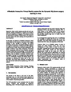
Figure 1. The CLEVR’s spiral model of VR system development.
meshes well with the concept of concurrent consideration of form, function, and behavior; that is, the specification in each dimension proceeds incrementally, affecting each other along the way. On the other hand, employing a hierarchical style in the incremental development process promotes a performance-conscious design by forcing the developer to focus on the more critical features in form, function, and behavior in a top-down manner. Intermediate models obtained from the hierarchical modeling approach can be used for LODs as well. At each abstraction level, in order to validate the models (for example, behavioral correctness, visual effect, performance) and perform further refinements, they must be simulated or executed.
3.3 The Spiral Process In general, this specification and simulation-driven validation process continues in a stepwise and incremental fashion. For instance, a form object may be further refined into a set of constituent subobjects (such as a car subdivided into its body and wheels), and their corresponding behaviors and functions would be refined accordingly. From the viewpoint of the whole development cycle, the overall modeling process follows a spiral software development model (Boehm, 1988) (see figure 1), and the basic iterations of “Requirements— Design—Validation” occur continuously at each stage. Features that distinguish the VR systems from others— like the required framerate, styles of interaction, LODs and their switching rules, and presence—are mostly dealt with during second- and third-stage iterations.
386 PRESENCE: VOLUME 11, NUMBER 4
4
P-VoT: Tools to Support CLEVR
P-VoT represents a collection of tools to support the CLEVR modeling approach. The major required functionalities are ways to construct and represent information regarding the form, function, and behavior of a virtual object and coalesce the information into an executable object-oriented form. The next step is to simulate (or execute) these evolving specifications and collect performance data for validating the behavioral correctness and performance tuning, and to save and organize different alternative model configurations for experimentation, as well as usage in dynamic model switching during execution. Note that interaction models, presence elements, special effect behaviors, and even model switching behaviors can all be represented as specially tailored derivatives of the constructs to represent funtion or behavior. Currently, P-VoT includes tools that provide only a subset of the functionalities previously listed, which are not integrated under one roof. In this section, we describe the specification constructs and the simulation environment.
4.1 Specification Method The major part of a system specification in CLEVR consists of a scenario, class diagram, and explicit representations of form, function, and behavior of objects that appear in the scenario and class diagram. 4.1.1 Scenarios. In CLEVR/P-VoT, the specification process starts by drawing several Message Sequence Diagrams (MSDs). The MSD depicts typical scenarios of internal and external behaviors of a VR world in terms of a sequence of data or control signals exchanged among objects in the system. (See figures 7 and 8.) In addition to using MSDs as test scenarios for later model validation, they prompt the user to identify important “functional” objects in the system. In fact, objects in a VR system may be classified into those that are purely functional, and those that are “spatial,” having “form” (that is, geometric spaces). Note that, with spatial objects, it is simply natural to model “things with geometry” as spatial objects. Constructing MSDs also
aids in identifying the sequences of the messages among various objects and picturing how they interact with one another. In particular, external devices can be treated as an object for human– computer interaction modeling. Object classes are then found by examining the identified objects and grouping them according to their commonality in form, function, and behavior. 4.1.2 Class Diagram. A class diagram shows the existence of classes and their relationships in the logical and brief view format. The class diagram notation in P-VoT follows that of the Unified Modeling Language (UML) (Fowler & Scott, 1997). The diagram includes association, aggregation, composition, and inheritance relationships; multiplicity and navigation indicators; and role names. Relationships provide a path for communication between objects. MSDs are examined to determine which type of links among objects must exist to accomplish the specified interaction. We note the relationships of aggregation and composition that exhibit different implications regarding the life cycle of the associated objects. In other words, an aggregation between a master and a slave object can be dynamically disconnected, with their life cycles separate, whereas a composition between two objects is decided statically, with their life cycles identical. It is important to begin the overall modeling process with a consistent view of object orientation as seen by the behavior/function specification process and form design. Figure 2 shows the modeling process to specify and validate a system. As figure 2 illustrates, each aspect (form, function, or behavior) is treated using appropriately different representation constructs and merged into a single object model. With a clear picture of a system configuration in terms of constituent objects and information flows between them, detailed behavior, function, and form specification of each object may start. We explain the behavior and function specification in the next subsection. 4.1.3 Behavior and Function Specification. Next, we proceed to specify the intended behavior and refine the functional structure of each object in the MSD using the statecharts and DFD. The behavior and
Seo and Kim 387
Figure 2. The object modeling process: form, function, behavior merging into an object.
function models are constructed using formalisms of the statecharts and the Data Flow Diagrams (DFDs) respectively, both available from P-VoT. A DFD specifies a single process or a function in terms of how it can be decomposed into a number of subprocesses or objects and their input/output relationships. A DFD may have a corresponding statechart that specifies how the processes behave; that is, it specifies when to execute the processes according to the states. (See figure 10.) For a more detailed explanation of their exact formalisms, please refer to (Harel, 1990). For simple isolated behaviors with a limited number of states and a simple computation structure, we believe a script-based description would suffice, as best exemplified in Alice (Carnegie Mellon University, 2001). (Such a facility is not available in P-VoT as yet.) Computational processes in the DFD are expressed using a “neutral” specification language. The statecharts/DFD constructs can be executed by “translating” them into a target implementation language/API (according to their semantics), and compiling them for
an appropriate execution platform. It is very important that the evolving system design be executed and tested in the actual execution platform for the performancetuning purpose. However, the “code” translation process is not straightforward, as the execution platform must efficiently implement the semantics of the statecharts and DFD. (Otherwise, performance tuning loses much of its meaning.) Although an option, a manual translation would be difficult and defeat the purpose of taking advantage of the intuitiveness of using statecharts or DFDs. Subsection 4.2 briefly discusses a semiautomatic translation process by augmenting the usual VR execution platforms (such as WorldToolKit) with a simple state machine. For an object-oriented simulation platform, the translation process would consolidate the function/behavior and form descriptions (to be explained in the next subsection) into an object-oriented form. The separate form/function/behavior descriptions and the consolidated executable objects can all be saved for later “spec/code reuse” and facilitate experimentation for performance or even usability. For instance, several different interaction models could be easily expressed using the DFDs, and the most appropriate one would next be chosen, based on user preference. 4.1.4 Form Specification. Specification of form may proceed in an interleaved fashion influenced by ongoing behavior/function modeling. Take, for instance, the system specification explained in subsections 4.1.1 and 4.1.2. The form specification would start by capturing the initial approximate shape/volume as well as the configuration of those objects. Like behavior or function, form is further refined in an incremental fashion, such as by subdividing a car into its components, such as body, wheels, doors, and so forth. The form is expressed using the Visual Object Specification (VOS) tool/language. Its primary purpose is to allow developers to easily describe the physical properties and configuration of a physical entity. Typical types of such attributes include shape, material, position, velocity, acceleration, force, angular velocity, angular acceleration, torque, and so forth. Users can define additional properties as needed. In addition, a form itself may in-
388 PRESENCE: VOLUME 11, NUMBER 4
Figure 4. Simulation environment structure of P-VoT. Figure 3. Class templates for a dynamic object.
clude primitive function or behavior. Here, the primitive behavior/function refers to the low-level behavior/ function that the user does not care to specify. For instance, a moving object might have a primitive “constant speed” behavior controlled by the target location only. Another moving object might display a primitive “accelerate-constant speed-decelerate” behavior instead. More-complex or higher-level function/behavior would be expressed using statecharts or DFD. The VOS library objects provide object classes for representing objects with typical spatial motions, such as linear acceleration, linear velocity, angular acceleration, and angular velocity. Figure 3 shows meta-class templates representing spatial (that is, occupies some space) and dynamic (changes its properties) objects. All virtual objects with form will inherit from the SpatialObject and possess basic attributes like shape, position, and orientation. They are further classified into dynamic (those that move), static (those that do not move), active (those that trigger other objects to move), and passive (those that are not active). Active objects control passive objects by having them as a “passive” child in a scene graph-like hierarchy. Notice that the Observer is a subclass of the DynamicObject, which is a subclass of the SpatialObject.
VOS also provides ways to specify explicit physical relationships or constraints among physical objects (such as a block’s location follows the tip of the end effector after it is grabbed). Inter-object spatial constraints make physical objects affect one another dynamically. For example, placing a screw on a conveyor belt is realized by explicitly defining a dynamic structural constraint between the conveyor and the screw. Spatial constraints can be used to define a structure similar to a scene graph. A scene graph structure organizes a composite object by a tree, wherein the coordinate system of children objects (constituents of the parent object) is defined relative to that of the parent object. When a motion is applied to the parent, all of its children are affected by it as well. Constraints are encoded using a predicate logic-like language, and the simulation would have to be equipped with an event/constraint checking routine for the corresponding constraints (for example, collision).
4.2 Simulator and Code Translator To simulate these specifications constructed separately for form, function, and behavior (although related to one another) and/or transform them into an implementation model that can be compiled and executed in
Seo and Kim 389
Figure 5. A snapshot of the VOS tool for constructing form specifications. It provides constructs to make incremental and hierarchical specifications for objects with form, and visualizes them.
a target platform, P-VoT offers the specification simulator (figure 4) and the code generator (figure 6). The simulation engine reads in specifications of components (or objects) and executes them in an interpretive fashion, then sends the simulation results to the object monitor and the scene viewer. The object monitor shows a variety of data about objects, such as the currently activated states of objects, transitions among states, values of data attributes, operation status of functions, and so on. The scene viewer renders objects that possess form. Through it, developers can validate behaviors of objects and performance visually (figures 5 and
12). The event manager of the simulation engine watches for generations of events from objects and relays them to other objects. The data manager supervises data attributes of objects and, upon changes, informs other objects with data dependency. The performance data collected from the interpretive simulation environment is bound to be unrealistic because actual implementation platforms have different computational models or rendering mechanisms optimized in their own right. Therefore, to collect more correct performance-related data and tune the system accordingly for a given implementation platform, P-
390 PRESENCE: VOLUME 11, NUMBER 4
Figure 8. MSD of the scenario “Create an AutoShip.” ( The asterisks indicate periodic messages.)
Figure 6. An example of translated codes.
the statecharts assigned to an object. It maintains an event prediction table for performance improvement. This table updates the list of events that are required to transit from a set of current states to other states. By updating this table, unwanted events can be rejected quickly. When one object is translated into the corresponding C⫹⫹ code, the following four files are generated by inheritance from the base classes. ●
●
Figure 7. MSD of the scenario “Increase the velocity of MyShip.” ●
VoT provides a semi-automatic translation of the specifications into C⫹⫹/WorldToolKit or Java/Java3D. In the case of C⫹⫹/WTK, P-VoT provides a static library that is linked with the translated code for compilation. The library consists of base classes from which the classes of translated code inherit. One of the core classes is the “StateTree” class, which is the engine that runs
●
具Object Name典_States.h: It includes information about all the states in the behavior specification of the object. Each state inherits from the State base class. 具Object Name典_Transitions.h: It includes information about all the transitions in the behavior specification of the object. Each state inherits from the Transition base class. 具Object Name典_Code.h: It inherits from the State Tree base class and specifies the connection between states and transitions in States.h and Transition.h. It also includes the object templates (that is, data and methods). 具Object Name典_Proxy.h: It manages outgoing events and determines where they should go.
Figure 6 shows an example of the generated code for one state (“CHANGING”).
Seo and Kim 391
Figure 9. The simplified class diagram for the ship simulator obtained after drawing the MSDs. Quite a number of object classes are inter-related in a complex manner.
5
Example: CLEVR Ship Simulator Design
In this section, we illustrate the whole modeling process more concretely by applying CLEVR to the design of a ship simulator. The major purpose of the ship simulator example application is to assist trainees to navigate in and out of the pier and come to an anchor without colliding with other vessels or the coast. At a first glance, the major objects to be modeled seem to be the trainee vessel (called MyShip) and the “other” automatically controlled vessels (called AutoShips), and the complexity and distribution of Autoships appear to be major parameters in tuning the performance of the whole system.
5.1 Specification (Stages 1, 2, and 3) The specification of the Ship Simulator, according to the spiral process of CLEVR, will proceed first by sketching the rough scenario, identifying the important objects and validating their basic functionalities (first stage). Then, additional requirements such as interaction design and presence enhancement are dealt with during the next stages of specification.
5.1.1 Scenarios and Object Identification: As described in subsection 4.1, the specification starts by making scenarios using the MSD. For the ship simulator, we draw MSDs to model possible and typical interactions between the trainee and the simulator, and among internal objects of the simulator. Figure 7 is the first simple example of the MSD: a trainee interaction scenario for “Increase the velocity of MyShip.” It describes a keyboard-based interaction for the trainee to operate his vessel. The MSD of figure 7 starts with the message “press key up” initiated by the trainee, which then triggers a message “increase power” to MyShip. Figure 8 shows another example of an MSD for a “Create an AutoShip” scenario. It shows the interaction among internal objects of the system. First, an object ShipSimulator creates an object AutoShip and sets the initial position of AutoShip. Next, three periodic messages (shown with asterisks) for maintaining the ship velocity are automatically generated (to simulate the fact that all ships are aware of the whereabouts of other ships). 5.1.2 Overall System: Figure 9 shows the simplified class diagram created by constructing various MSDs. Notice the objects like Mouse, Fastrak (for an-
392 PRESENCE: VOLUME 11, NUMBER 4
Figure 10. The second level DFD of ShipSimulator.
other interactive task), Camera (for view control), Environment (static terrain/sky/sea models that have no particular behavior), and ShipSimulator (a formless entity that abstracts various simulator functions). As noted, the relationships among classes are cleared up in this stage of the modeling. A trainee can operate Myship through Keyboard, then MyShip moves Camera. He can also change the orientation of Camera through Mouse or Fastrak, but the change in Camera does not affect MyShip. Note that the relationship between ShipSimulator and MyShip is an aggregation, whereas the relationship between ShipSimulator and AutoShip is a composition. This initial class diagram is subject to revision during the next phases of development. 5.1.3 Polygon Budgeting: After the initial class diagram is completed, we continue by specifying details of form, function, and behavior for each object. For objects with form, we plan for a suitable level of geometric complexity in the object’s form through the polygon budgeting process (Hoffman, 1997). In polygon budgeting, the suitable number of polygons is decided by considering the processing and rendering capacity of the target execution environment. Table 1
assumes that a target platform can process about 35,000 polygons per frame. We initially determine the estimates, including polygon counts. The number of LODs and their distribution are initially determined by the properties of the application, but they are also subject to change upon iterative performance and presence tuning during later stages. 5.1.4 Modeling of Functional Objects—ShipSimulator: In this subsection, we highlight the general process of specifying the function and behavior of an object—in this case for ShipSimulator (a formless object that subsumes various control functions for the simulator)—to show how they are coupled to one another. Figure 10 is the diagram of the second-level DFD.2 ShipSimulator is composed of three processes: “SetInitialPosition” that decides the initial position of AutoShip, “CheckCollision” that checks collisions with other objects, and “SetMyShipPosition” that accepts a newly joined MyShip for training (Several users may be being trained at the same time.) All the leaf (not to be refined 2. The second-level DFD in this paper is refined from a top-level DFD, also called a context diagram, which is omitted on purpose.
Seo and Kim 393
Figure 11. Statecharts of the controller ShipSimulatorController.
further) process blocks (circular blocks in the DFD) have “process specifications” that describe the actual computation performed by the process block. (The circular blocks with asterisks are all leaf processes and have their own process specifications.) This is expressed using an intermediate language similar to the C language. The DFD must have a controller (the rectangular box in figure 10) that is responsible for initiating and coordinating process executions (when it has one or more leaf processes), and bringing about state transitions. The internals of the controller is specified using statecharts, as shown in Figure 11. In this example, the process “SetInitialPosition” generates the event “initComplete” that triggers a state transition for ShipSimulator.
This controller changes its state from “Idle” to “DoingSimulation” by the event “start,” and the state “DoingSimulation” has three concurrent states that manage AutoShips, MyShips, and TUGboats simultaneously. Because all the instances of AutoShip are generated automatically at the beginning, the state “AutoShipControl” changes its substate to the “AutoShipChecking” state after the instances of AutoShip are created and initialized successfully. The “MyShipControl” state notifies the initial positions/orientations of instances of the joining MyShips and returns to the “WaitingMyShip” state to wait for another MyShip to join for training. At this point, the specifications can be validated by simulating the specifications. (See figure 12.)
394 PRESENCE: VOLUME 11, NUMBER 4
Figure 12. Snapshot of function and behavior simulation in P-VoT. Statecharts and DFDs (bottom half) are animated as they are simulated, controlled by a control panel (upper right), and state/data information are shown simultaneously (upper middle).
5.1.5 Modeling User Interactions: Although the behavior and function of MyShip is simple, it is the only object that has dynamic behavior controlled by user interactions. As you can guess from subsections 5.1.1 and 5.1.2, a trainee can interact with the system, using a keyboard, a mouse, and a Polhemus FASTRAK 6D tracker. The following statecharts of Keyboard depicts how a trainee controls the velocity and orientation of one’s vessel using various keys. Once transiting into a proper ship control state, it returns to the “ready” state upon a “key_processed” event. (It should not be in the “increasing_power” state
permanently!) In the case of using a continuous device, such as the tracker, we need to poll the data from the device. The procedure for specifying a periodic process using the formalism of statecharts is easily accomplished. 5.1.6 Modeling of Objects with Form (and their LODs)—AutoShip: In this subsection, as the last example of object modeling, we demonstrate the process of concurrent modeling of form and behavior and LOD generation. In the case of AutoShip, we start with a very simple form model of a ship (for no particular
Seo and Kim 395
Figure 13. Snapshot of interaction modeling using P-VoT.
reason, we could very well start with a rough function/ behavior model instead). This simplest form model (G1) is composed of a set of boxes and has 106 polygons, roughly within the estimate of the initial polygon budget. (See table 1.) At this point, we can think of a simple behavior model (B1) that can accompany this simple form model, which starts to navigate from a random position and orientation and changes its velocity and angular velocity at random periods. Further, if it detects a collision with other ships or the coastline, it moves in the opposite direction and starts to navigate at a new velocity again. (See figure 14.) Next, we proceed to the next behavior model, B2. (Again, we could begin refining the form first.) The B2 behavior model is generated by adding a new concurrent behavior for rotation of the radar to the B1 behav-
ior model. This new behavior model is not “compatible” with the G1 form model because some geometric parts (such as the radar) are necessary. Thus, the next geometric model, G2, is produced by adding the radar geometry along with other parts for a more realistic appearance (365 polygons). Next, we proceed to the third-level form model because we originally planned to generate three levels of details for the AutoShip. We chose not to refine the behavior model further. We refine the geometric model to G3 (figure 15) by adding windows and other parts for a more realistic visualization (645 polygons). The incremental and hierarchical nature of the modeling process naturally leads to the generation of LOD models both for geometry and behavior. Figure 16 depicts the overall refinement process of AutoShip, and the
396 PRESENCE: VOLUME 11, NUMBER 4
Table 1. A Polygon Budget Table Object MyShip AutoShip
LOD1 LOD2 LOD3 Env. (Sky, Terrain. . .) Total
Number of objects
Total polygons
Polygons per objects
1 80 48 16 1
500 8,000 14,400 9,600 3,000 35,500
500 100 300 600 3,000
5.2 Performance Estimation and Model Selection
Figure 14. The first-level form and behavior model of the AutoShip.
arrows represent the sequence of refinement. Note that the flow and number of refinements (or the number of LODs) may vary according to the intent of the developer, and, as long as the “compatibility” condition is kept, any geometric and any behavior model can be combined. In fact, we redefine LOD as a particular combination of two compatible geometric and behavior models (see table 2) (Seo & Kim, 1999).
At this stage, we are ready to run a simple simulation to estimate the approximate performance of the system using various mixes and distributions of these LOD models. (We assume that, because there are relatively many AutoShips, it dominates the load on the processor and the graphics board.) As the application required the AutoShip cardinality at around 300 to 400, we check the performance by simulating those amounts of AutoShips at five different LODs, as shown in table 2. Figure 17 shows the simulation environment. Table 3 shows performance test results in terms of the average framerates for each chosen LOD. Although the results3 show the expected trivial fact that more-complex models produce lower framerates, we observe that the variances in the framerates are not linear. For instance, if we were to select a two-LOD mix for the case of 300 ships, we might choose L2 and L3, because they have higher details at a similar cost versus L1 and L4 respectively.
5.3 Presence/Special Effects: Third Stage of Spiral Process In subsection 3.3, we explained the spiral process, which is one of the modeling philosophies in the CLEVR.
3. The simulation was performed on a desktop PC with an Intel Pentium 4 1.4 GHz CPU, 512 MB bytes (RDRAM) main memory, and an Nvidia Geforce2 MX graphics card, using MS Windows 2000, WorldToolKit, and MS Visual C⫹⫹.
Seo and Kim 397
Figure 15. The third-level form model of the AutoShip.
Table 2. LOD as Combination of Compatible Geometry and Behavior Models
B1 B2
G1
G2
G3
L1(G1, B1) N/A (incompatible)
L2(G2, B1) L4(G2, B2)
L3(G3, B1) L5(G3, B2)
Figure 16. Refinement process of the object AutoShip.
The spiral process has three stages and the basic iterations of “Requirement Analysis—Design—Validation” occur continuously at each stage. In this subsection, we illustrate the third stage of the modeling process, in which we assume that the most-basic parts of the system have been designed and tested for, and thus we can start worrying about special effects and other elements that may improve the overall presence of the VR system. 5.3.1 A More Realistic Behavior of AutoShip: Table 3 showed that, even with 400 AutoShips, we would be able to obtain up to 30 – 40 fps performance, depending on a careful choice of an LOD mix. We choose to refine the second-level behavior model of the AutoShip by adding two concurrent states, so that the ship rolls and pitches to express the movement caused by the waves and the wind (B3). Now, two compatible combinations of the geometric and behavior LOD models—L6 ⫽ (G2, B3) and L7 ⫽ (G3, B3)—are cre-
ated and should be tested. The last row of table 4 shows the new LOD models (L6 and L7), and table 5 is the updated performance result with the newly added LODs. The three seemingly appropriate LODs for the three-LOD mix are indicated in boldface for each case. 5.3.2 Special Effects: Environment is composed of a set of static form (geometric) objects: for example, the sea surface (a big polygon with a nice-looking sea surface texture), the semi-spherical sky, and the terrain data (for simple rendering of the coast). After confirming that the framerate of up to 40 fps could be achieved (depending on the careful selection of LOD models for the AutoShip and their cardinalities), we thought of three ways to further enhance the realism or presence. The first special effect we tried to add was fog. At the specification level, this amounted to simply adding a new attribute to the Environment, and, this in turn, produced a “one-line” graphics call to activate the fog effect. The graphics hardware we
398 PRESENCE: VOLUME 11, NUMBER 4
Figure 17. Snapshot of visual simulation with LOD mix selection in P-VoT. User experiments with various LOD object models and their cardinality to assess overall performance and presence effect.
used did not introduce any significant performance drop when the fog effect was used. (See table 6.) The next special effect applied to improve the appearance of the sea was the use of a moving texture technique. Instead of using a big static texture polygon, we employed a simple logic to rotate through four texture images to simulate the dynamics of the sea. (Figure 19 shows this newly added behavior of Environment.) ShipSimulator determines the period according to the parameters of the simulation environment; that is, the velocity of the wind and the height of the wave, and
Table 3. Simulating 300, 350, and 400 AutoShips with Different LODs Average framerate LOD
300
350
400
L1(G1, B1) L2(G2, B1) L4(G2, B2) L3(G3, B1) L5(G3, B2)
41 43 33 34 27
41 37 26 28 23
40 30 22 25 18
Seo and Kim 399
Figure 18. The third-level behavior model of AutoShip.
Table 4. The New LOD Models G1
G2
Table 5. The Simulation Results with New LODs G3
B1 L1(G1, B1) L2(G2, B1) L3(G3, B1) B2 N/A (incompatible) L4(G2, B2) L5(G3, B2) B3 N/A (incompatible) L6(G2, B3) L7(G3, B3)
generates the event “next_texture.” Again, our system set-up, equipped with texture cache like most of today’s VR API or graphics hardware, did not introduce any significant performance drop. Finally, we implemented a more realistic sea surface movement through a mesh deformation scheme. A part of the sea surface was remodeled using a 50 ⫻ 50 vertex grid composed of triangular polygons, and a simple physically based algorithm was applied to simulate a wavy sea surface. As shown in table 6, this final addition resulted in quite a drop in the overall performance. Although not tested experimentally, the improvement in the realism or presence was most apparent with the
Average framerate LOD
300
350
400
L1(G1, B1) L2(G2, B1) L4(G2, B2) L6(G2, B3) L3(G3, B1) L5(G3, B2) L7(G3, B3)
41 43 33 30 34 27 25
41 37 26 23 27 23 18
40 30 22 19 25 18 16
mesh deformation effect. Without an objective experiment, however, it would be up to the system developer’s perception to choose the LOD and special effect mix to determine the final system configuration. Considering few other (none dominating) objects (for such as MyShip, Coast), our conservative choices of LOD and special effects mix are highlighted in the table.
400 PRESENCE: VOLUME 11, NUMBER 4
Table 6. The Simulation Results of Environment with Three Special Effects and Different LOD Mixes. A Three-LOD Mix Scheme was Used in Which Its Distribution was Set at High/Medium/Low ⫽ 1/3/5 (Ships Proportionally Distributed in Three Distance Regions) Result (average/fps) LOD Mix Ratio (1:3:5)
Fog
Moving texture
Ripple mesh
N ⫽ 300 L2 ⫽ 167, L3 ⫽ 100, L7 ⫽ 33
N Y N Y N Y N Y
N N Y Y N N Y Y
N N N N Y Y Y Y
39 32 38 30 27 23 29 24
Figure 19. Moving sea behavior by moving textures.
6
Discussion and Conclusion
This paper has presented CLEVR, a comprehensive structured methodology for building VR systems. The underlying modeling philosophies of CLEVR are the concurrent consideration of form, function, and behavior; hierarchical and incremental development and
N ⫽ 350 L1 ⫽ 194, L2 ⫽ 117, L5 ⫽ 39
N ⫽ 400 L1 ⫽ 222, L2 ⫽ 133, L5 ⫽ 45
35 35 27 27 30 23 29 25
41 33 40 32 27 22 26 22
simulation; and spiral modeling process. To support this modeling strategy, a collection of computer-aided tools, called P-VoT was also introduced. It would be quite difficult to quantitatively show the utility or effectiveness of the proposed methodology in terms of reduced cost in development and maintenance due to the lack of objective metrics and the qualitative and even fuzzy nature of most software engineering studies. Instead, we have illustrated a step-by-step application of CLEVR/P-VoT to a design of a virtual ship simulator in hopes of convincing the readers of the benefits of the proposed methodology. Through the example, we showed how the specifications of form, function, and behavior of a VR object were related to one another, how interactions and performance issues and presence enhancing elements were considered, and how the specification evolved from the abstract to detailed and executable models. Applying a structured design method makes sense when the target system is relatively large and highly complex, and our example partly illustrates this aspect as the system was tested with up to 400 instantiated objects with several levels of details and interacting behaviors. In fact, enriching VR content often amounts to increasing the number of objects and
Seo and Kim 401
detailing their behavior and interactions. Accurate (computational, storage and graphics subsystem) cost models would be required to predict how the system will behave when such a system scale-up occurs. Our experience demonstrated that, with the lack of such cost models and the difficulty to establish them (due to unknown factors in the operating system and the graphics subsystems), our conservative and incremental performance check (that is, check the basics first then apply extra special effects later) along with the LOD selection scheme helps the developer by reducing the potentially large design alternative space as the systems grows larger. We claim that a structured approach such as CLEVR/P-VoT enables an effective exploration of various alternatives for a domain with fairly large design possibilities such as VR systems (for example, with respect to performance, interaction, and presence). Without the exact model of what constitutes a “highly present” VR content, choosing the final system configuration is basically a trial-and-error process, dependent on the perception of the system developer and thus always subject to change and further tuning. It goes without saying that simply leaving at least rough specifications of the VR objects and their organizations—and documenting the functional requirements and rationale of the design choices—would prove to be beneficial in later maintenance. Moreover, the early and incremental validation of the model is likely to reduce the cycles of the usual trial-and-error process of system tuning for the required performance and usability and change in content and interaction methods. However, we have only scratched the surface of this research area. Many related issues must be addressed to truly make CLEVR/P-VoT a complete development method for VR systems. One important aspect is rapid prototyping, an issue that entails reusing object specifications and leveraging off predefined performance or usability models within the context of CLEVR/P-VoT. We also plan to introduce (or improve) the specification/simulation tools, making them easier to use and more tightly integrated with formally clear semantics.
Acknowledgments The work presented in this paper has been supported in part by the Korea Ministry of Education’s BK21 Project and Korea Science and Engineering Foundation (KOSEF) supported Virtual Reality Research Center.
References Adachi, Y., Kumano, T., & Ogino, K. (1995). Intermediate representation for stiff virtual objects. Proceedings of IEEE Virtual Reality Annual International Symposium (pp. 203– 210). Barfield, W., Zeltzer, D., Sheridan, T., & Slater, M. (1995). Presence and performance within virtual environments. In W. Barfield & T. Furness (Eds.), Virtual environments and advanced interface design (pp. 473–513). New York: Oxford University Press. Boehm, B. (1988). A spiral model for software development and enhancement. Computer, 21(5), 440 – 454. Carlson, D. A., & Hodgins, J. K. (1997). Simulation levels of detail for real-time animation, Proceedings of Graphics Interface (pp. 1– 8) Carnegie Mellon University. (2001). Alice: Free, Easy, Interactive 3D Graphics for the WWW. Retrieved May 10, 2002 from the World Wide Web: http://www.alice.org Carroll, J. M. (1998). Making use: Scenario-based design of human-computer interactions. Cambridge: The MIT Press. Chen, S. E. (1995). QuickTime VR: An image-based approach to virtual environment navigation. Proceedings of the 22nd annual ACM conference on Computer Graphics (pp. 29 –38). Cohen-Or, D., Chrysanthou, Y., & Silva, C. T. (2001). A survey of visibility for walkthrough applications. SIGGRAPH 2001 Course Notes on Visibility, Problems, Techniques and Applications (pp. 44 – 65). Colbert, E. (2000). How RapidPlus Speeds Development of Embedded Systems that Satisfy Customers. Retreived May 13, 2001 from the World Wide Web: http://www.e-sim.com/ user_downloads/PDF/whtpaper.pdf. DeMarco, T. (1979). Structured analysis and system specification. Yourdon, NY: Prentice-Hall. Elliott, C., Schechter, G., Yeung, R., & Abi-Ezzi, S. (1994). TBAG: A high-level framework for interactive, animated 3D
402 PRESENCE: VOLUME 11, NUMBER 4
graphics applications. Proceedings of the 21st annual conference on Computer graphics (pp. 421– 434). Ellis, S. (1991). Nature and origin of virtual environments: A bibliographical essay. Computer System in Engineering, 2(4), 321–347. Engineering Animation, Inc. (1999). WorldToolKit reference manual. Fishwick, P. (1996). Extending object-oriented design for physical modeling. ACM Transactions on Modeling and Computer Simulation. Submitted July 1996. Fowler, M., & Scott, K. (1997). UML distilled: Applying the standard object modeling language. New York: Addison Wesley. Gaskell, C., & Phillips, R. (1995). Software architecture of the executable graphical specification tool EGS1. SoftwareConcepts and Tools, 16(3), 124 –135. Gobbetti, E., & Balaguer, F. (1993). VB2: An architecture for interaction in synthetic worlds. Proceedings of the Sixth Annual ACM Symposium on User Interface Software and Technology (pp. 167–178). Greene, N., Kass, M., & Miller, G. (1993). Hierarchical Zbuffer visibility. Proceedings of the 20th Annual Conference on Computer Graphics (pp. 231–238). Harel, D. (1990). STATEMATE: A working environment for the development of complex reactive systems. IEEE Transactions on Software Engineering, 16(4), 403– 414. Heeter, C. (1992). The subjective experience of presence. Presence: Teleoperators and Virtual Environments, 1(2), 262–271. Hoffman, W. (1997). Database design for visual simulation and entertainment. SIGGRAPH 97 Course Notes on Designing Real Time Graphics for Entertainment (pp. 175–186). Hubbold, R., Cook, J., Keates, M., Gibson, S., Howard, T., Murta, A., West, A., & Pettifer, S. (1999). GNU/ MAVERIK: A micro-kernel for largescale virtual environments. Proceedings of ACM Symposium on Virtual Reality Software and Technology (pp. 66 –73). Jacob, R., Deligiannidis, L., & Morrison, S. (1999). A software model and specification language for non-WIMP user interface. ACM Transactions on Computer-Human Interaction 6(1), 1– 46. Kang, K. C., Lee, K. W., Lee, J. Y., Kim, G. J., & Kim, H. J. (1998). ASADAL/SIM: An incremental multi-level simulation and analysis tool for real-time software specifications. Journal of Software: Practice and Experiences, 28(4), 445– 462. Kim, G. J., Kang, K. C., Kim, H. J., & Lee, J. Y. (1998). Soft-
ware engineering of virtual worlds. Proceedings of the ACM Symposium on Virtual Reality Software and Technology (pp. 131–138) Lubeke, D. (1999). A developer’s survey of polygonal simplification. IEEE VR Conference Tutorial 7 Course Notes. McMillan, L., & Bishop, G. (1995). Plenoptic modeling: An image-based rendering system. Proceedings of the 22nd Annual ACM Conference on Computer Graphics (pp. 39 – 46). Paradigm Simulation, Inc. (1996). VEGA programmer’s guide. Pausch, R., Burnette, T., Copeheart, A. C., Conway, M., Cosgrove, D., DeLine, R., Durbin, J., Gossweiler, R., Koga, S., & White, J. (1995). Alice: Rapid prototyping system for virtual reality. IEEE Computer Graphics and Application, 15(3), 8 –11. Perlin, K., & Goldberg, A. (1996). Improv: A system for scripting interactive actors in virtual worlds. Proceedings of the 23rd Annual Conference on Computer Graphics (pp. 205–216). Rohlf, J., & Helman, J. (1994). IRIS performer: A high performance multiprocessing toolkit for real-time 3D graphics. Proceedings of the 21st Annual Conference on Computer Graphics (pp. 381–394). Schmalstieg, D. (1997). A survey of advanced interactive 3-D graphics techniques. Research paper, Institute of Computer Graphics, Vienna University of Technology. Seo, J. S., & Kim, G. J. (1999). Levels of detail (LOD) engineering of VR objects. Proceedings of ACM Symposium on Virtual Reality Software and Technology (pp. 104 –110). Seo, J. S., Kim, D. N., & Kim, G. J. (2001). VR object reuse through component combination. International Workshop on Structured Design of Virtual Environments and 3D-Components. In press. Sheridan, T. B. (1992). Musings on telepresence and virtual presence. Presence: Teleoperators and Virtual Environments, 1(1), 120 –126. Sowizral, H., Rushforth, K., & Deering, M. (2000). The Java 3D API specification, 2nd ed. Reading, MA: AddisonWesley. Sriram, D., Logcher, R., Grouleau, N., & Cherneff, J. (1992). DICE: An object-oriented programming environment for cooperative engineering design. AI in engineering design, vol. III, C. Tong & D. Sriram Eds. (pp. 303–366). San Diego, CA: Academic Press. Turner, R., Gobbetti, E., Balaguer, F., Mangili, A., Thalmann, D., & Thalmann, N. M. (1990). An object-oriented methodology using dynamic variables for animation and
Seo and Kim 403
scientific visualization. Proceedings of Computer Graphics International (pp. 317–328). Turner, R., Li, S., & Gobbetti, E. (1997). Metis: An objectoriented toolkit for constructing virtual reality applications. Proceedings of Sixth Eurographics Workshop on Programming Paradigms in Graphics (pp. 79 –90). Welch, R. B., Blackmon, T. T., Liu, A., Mellers, B. A., & Stark, L. W. (1996). The effects of pictorial realism, delay of visual feedback, and observer interactivity on the subjective
sense of presence. Presence: Teleoperators and Virtual Environments, 5(3), 263–273. Wernecke, J. (1994). The Inventor mentor: Programming object-oriented 3D graphics with Open Inventor. Reading, MA: Addison-Wesley. Willians, J. S., & Harrison, M. D. (2001). A toolset supported approach for designing and testing virtual environment interaction techniques. International Journal of HumanComputer Studies, 55(2), 145–165.