International Archives of the Photogrammetry, Remote Sensing and Spatial Information Sciences, Volume XXXIX-B2, 2012 XXII ISPRS Congress, 25 August – 01 September 2012, Melbourne, Australia
A STUDY OF VARIABLES CHARACTERIZING DRAINAGE PATTERNS IN RIVER NETWORKS Ling Zhang *, Eric Guilbert
Dept. of Land Surveying and Geo-Informatics, the Hong Kong Polytechnic University, Hung Hom, Kowloon, Hong Kong KEY WORDS: River Network, Drainage Pattern, Terrain Analysis, GIS
ABSTRACT: In GIS and in terrain analysis, drainage systems are important components. Due to local topography and subsurface geology, a drainage system achieves a particular drainage pattern based on the form and texture of its network of stream channels and tributaries. Drainage pattern recognition helps to provide a qualitative description of the terrain for analysis and classification and is useful for terrain modelling and visualization and applications in environment. Much research has been done on the description of drainage patterns in geography and hydrology. However automatic drainage pattern recognition in river networks is not well developed. This paper introduces a method based on geometric quantitative indicators to recognize drainage patterns in a river network automatically. Experiment results are presented and discussed.
1. INTRODUCTION
2. RELATED WORK
Drainage system is the pattern formed by streams, rivers and lakes in a drainage basin. As an indivisible part of the land, drainage system is an important component in GIS and in terrain analysis. In a drainage system, streams or rivers always connect together to form networks. In current GIS systems, river networks are stored as line segments with their geographical coordinates and topological relationships. Inside a network, different patterns can be observed and related to other geographical factors. In a drainage basin, a number of factors such as topography, soil type, bedrock type, climate and vegetation cover influence input, output and transport of sediment and water (Charlton, 2008). These factors also influence the nature of the pattern of water bodies (Twidale, 2004). As a consequence, drainage pattern can reflect geographical characteristics of a river network to a certain extent.
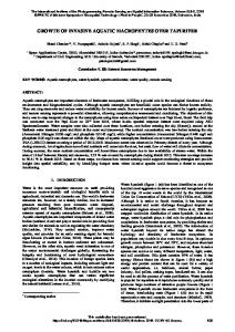
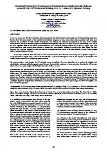
With the passage of time, a drainage system achieves a particular drainage pattern where its network of stream channels and tributaries is determined by local geologic factors. Drainage patterns are classified on the basis of their form and texture according to slope and structure. Their shape or pattern develops in response to the local topography and subsurface geology. River segments inside a river network can be organised in five types of drainage pattern (Figure. 1). Dendritic pattern (Figure 1a) is the most common form of river system. In a dendritic river system, tributaries of a main river join together in a shape analogous to the twigs of a tree (Lambert, 1998). Parallel patterns (Ritter, 2003) form where there is a pronounced slope to the surface. Tributary streams tend to stretch out in a parallellike fashion following the slope of the surface (Figure 1b). In a trellis pattern (Figure 1c), the main river flows along a strike valley and smaller tributaries feed into it from the steep slopes on the sides of mountains. These tributaries enter the main river at right angles, causing a trellis-like appearance of the river system. The rectangular pattern (Figure 1d) is found in regions that have undergone faulting. Movements of the surface due to faulting offset the direction of the stream. As a result, the tributary streams make sharp bends and enter the main stream at high angles. Reticulate drainage patterns (Figure 1e) usually occur on floodplains and deltas where rivers often interlace with each other forming a net (Simon and Gerald, 2004).
There are several types of drainage pattern. At present, much research has been done on the description of drainage patterns in geography and hydrology (e.g. Howard, 1967; Lambert, 1998; Twidale, 2004; Pidwirny, 2006). However, automatic drainage pattern recognition in river networks is not well developed. In this paper, several geometric indicators for the characterization of drainage patterns are presented and discussed on experiments. In GIS, such classification can be useful for terrain analysis or for generalization. At present, many researchers have started to pay attention to geographic features of river networks during the generalization process (Ai et al., 2007; Buttenfield et al., 2010; Stanislawski, 2009, 2011).
Some experimental works have been done about morphological dependencies of river channel patterns, such as straight, meandering and braid pattern. Schumm and Kahn (1972) obtained an experimental relationship between slope and sinuosity for a fluvial channel, which can show threshold changes between pattern types. Here, sinuosity is a ratio of channel length to valley length. Results show that braided pattern appears on steep low-sinuosity channels. Schumm (1977)
The paper is organized as follows. Section 2 briefly reviews related works in drainage pattern. In section 3, several geometric indicators are presented to recognize drainage patterns in a river network. In section 4, the method is tested in an experimental area, and the validity of indicators is discussed. Finally, conclusions and research perspectives are presented.
* Corresponding author. E-mail addresses:
[email protected] (L. Zhang),
[email protected] (E. Guilbert).
29
International Archives of the Photogrammetry, Remote Sensing and Spatial Information Sciences, Volume XXXIX-B2, 2012 XXII ISPRS Congress, 25 August – 01 September 2012, Melbourne, Australia
improved his model and pointed out that pattern adjustments, measured as sinuosity variations, are closely related to the type, size, and amount of sediment load. Although these works (e.g. Knighton, 1998; Lewin, 2001) about morphological dependencies apply to river channel pattern rather than river network, some of the indicators referred above can be considered in this paper.
scheme based on (Horton, 1945) and modified by Strahler (1957) and the Shreve scheme (Shreve, 1966). Junction
Source River segment
Node Catchment Sub-catchment
Outlet
a. dendritic
b. parallel
c. trellis
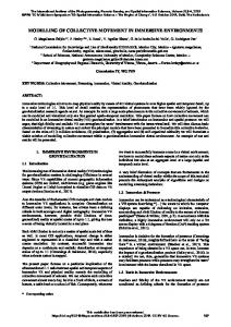
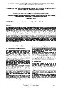
Figure 2. Features in river network (modified from Li, 2007) 3.2 Drainage Pattern Recognition
d. rectangular
In section 2, 5 types of drainage pattern were introduced. This work addresses the identification of the patterns based on geometric characteristics identified inside a network. According to the description given in section 2, Table 1 proposes a list of characteristics for each of them.
e. reticulate
Figure 1. Drainage network patterns (diagrams modified from Ritter, 2006)
The reticulate pattern is specific as rivers form a cycle instead of a tree. Therefore, recognition of reticulate patterns is discussed in the next section while identification of other patterns based on geometric indicators is introduced in section 3.2.2.
At present, much research has been done on the definition, classification and description of drainage patterns in geography and hydrology. Many scholars work on predicting river channel pattern from in-channel characteristic, such as slope and discharge, but not drainage pattern. Indeed, drainage pattern is recognized as an important element in GIS but its classification has not been considered yet. Therefore, the next section studies the geometric and topologic characteristics of each type of river patterns and presents a classification method based on several geometric quantitative indicators in river network.
Drainage pattern
Geometric and Topologic Characteristic
Dendritic
-Tributaries joining at acute angle
Parallel
- Parallel-like - Elongated catchment - Long straight tributaries - Tributaries joining at small acute angle
Trellis
- Short straight tributaries - Tributaries joining at almost right angle
Rectangular
- Tributary bends - Tributaries joining at almost right angle
3. DRAINAGE PATTERN RECOGNITION Based on the description of different drainage patterns, each pattern has its own characteristics, which can be reflected in some quantifiable variable related to some topological and geometrical aspects. Therefore, each pattern can be characterized by a combination of different variables. In this section, the method for drainage pattern recognition is introduced. First, terms describing river networks are defined then classification criteria are introduced and the different steps of the process are detailed.
Reticulate
- Tributaries cross together forming a cycle
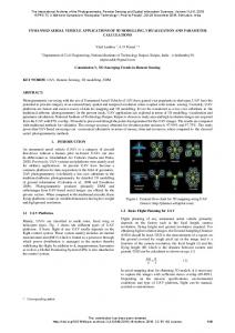
Table 1. Drainage pattern characteristic 3.2.1 Reticulate Pattern Recognition: In graph theory, a cut-edge (also known as a bridge) is an edge whose removal produces a graph with more components than the original (Bondy and Murty, 2008). Equivalently, an edge is a bridge if and only if it is not contained in any cycle. The figure 3 illustrates the cut-edges in an undirected graph, where the dashed line is cut-edge and the solid line is edge contained in a cycle.
3.1 Definition of Features in River Networks A river network is composed of several connected river segments. End points of the river segments are the nodes. There are three types of node: the junction node connecting river segments, the source node corresponding to river springs and the outlet towards where the flow goes. A river network is located in a catchment. The catchment controlled by a tributary flowing into a main stream is called a sub-catchment. All these features are illustrated in Figure 2.
A
D C
The river network forms a tree structure. The structure is built by assigning an order number to each tributary. Ordering starts by assigning order 1 to branchless tributaries. The order of a stream is always higher than the order of its tributaries so that the highest order is assigned to the segment connected to the outlet. Most relevant ordering schemes are the Horton-Strahler
F E
B
G
F
Cut-edge Edge in cycle
Figure 3. Cut-edges in an undirected graph
30
International Archives of the Photogrammetry, Remote Sensing and Spatial Information Sciences, Volume XXXIX-B2, 2012 XXII ISPRS Congress, 25 August – 01 September 2012, Melbourne, Australia
Considering the river network as an undirected graph, all cutedges are found using a bridge-finding algorithm (Tarjan, 1974). Edges which are not identified as cut-edges are components of cycles and form reticulate patterns.
stream as an indicator. The main stream is not a single river segment connected to the tributary but a series of consecutive segments with the same direction and same order (Figure 5).
3.2.2 Dendritic, parallel, trellis, and rectangular pattern recognition: In this section, some geometric quantitative indicators are defined to recognize these patterns. (1)Angle: From the geometric characteristics of drainage patterns in table 1, the most important variable is the angle formed by a tributary with its main stream at a junction node. The average angle of all angles in a catchment is one quantitative indicator.
Figure 5
(2)Sinuosity: In order to distinguish rectangular pattern, the shape of a tributary is needed. In this pattern, tributary streams make shape bends almost to right angle.
(4)Catchment elongation: The catchment elongation is characterized by the ratio of the depth to the breadth of the Minimum Bounding Rectangle (MBR) of the catchment. If the catchment is elongated, this ratio is large.
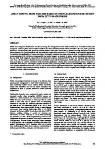
Schumm (1977) set the sinuosity variable of a stream as the ratio of the channel length to the valley length. If the sinuosity ratio is equal to or is greater than 1.5, the channel is considered to be meandering (Ritter, 2003). Only using length value to calculate the sinuosity would lose the information about the river shape. Sometimes a stream seems almost straight, but it would have approximate sinuosity ratio with bending stream, as shown in Figure 4. In order to distinguish angular streams in rectangular pattern from other patterns, a different method is used to identify bended tributaries.
The exact location of the catchment area is usually computed from the DEM which is not available. Approximations can be obtained from the river network such as the convex hull, the axis-aligned bounding box (AABB) or the oriented minimum bounding rectangle (MBR) (Figure 6). The objective is to estimate whether the catchment is elongated or not. The MBR of the river network is considered as it follows the orientation of the network. The breadth of the river network is given by the length of the MBR side which follows the orientation of the main stream while the other side corresponds to the depth. For example, in Figure 6, the depth is smaller than the breadth and the catchment area should be large so the drainage cannot be considered as parallel.
P1 Pi Pi-1
Pi+1
Main streams calculated in length ratio, arrow refers to the flow direction, the river segments in dashed box are main streams.
PN
a. almost straight Pi Pi+1 P1
Pi-1 PN
b. bending
Figure 4 River segment represented as a polyline Supposing a river segment is composed of N points Pi with P1 and PN the end points (Figure 4). There are N-1 vectors Pk Pk 1 1 k N 1 . A set of angles Ω are formed by vectors:
( P1 P2 , Pj Pj 1 ) | 2 j N 1
Figure 6
If the maximum value among these angles is close to 0°, it indicates that the river segment is almost straight; otherwise, if it is equal to or greater than 90°, it shows that the river segment has an obvious turning which is a bended tributary. So, the maximum value MAX () is used to indicate the river segment sinuosity level.
MBR of a river network. The edge Edge_a has a bigger angle with mainstream, ratio = Edge_b / Edge_a< 1, it is not an elongated river basin.
Geometric characteristics of different patterns presented in Table 1 are only defined qualitatively. In order to identify patterns based on these characteristics, statistical measures are obtained from the network and compared with threshold values.
(3)Length ratio: It is the ratio of tributaries to main stream is the third indicator. The difference between parallel and trellis pattern is length, the tributaries in parallel pattern are long relative to trellis.
The first parameter is the angle between the tributaries and the main stream. The parameter is given by the average value α of angles measured at all junctions. Dendritic pattern only requires that junction angles are acute, which can translate by α