A Study on the Enhanced Detection Method Considering the Channel Response in OFDM Based WLAN Hyoung-Goo Jeon1, Hyun Lee2, Won-Chul Choi2, Hyun-Seo Oh2, and Kyoung-Rok Cho3 1
Dong Eui University, Busan, Korea
[email protected] 2 Electronics and Telecommunications Research Institute, Daejeon, Korea {hyunlee, wcchoi, hsoh5}@etri.re.kr 3 School of Electrical Engineering Chungbuk Nat’l University, Chungbuk, Korea
[email protected]
Abstract. In this paper, we proposed a channel estimation method by impulse signal train in OFDM. In order to estimate the channel response, 4 impulse signals are generated and transmitted during one OFDM (Orthogonal Frequency Division Multiplexing) symbol. The intervals between the impulse signals are all equal in time domain. At the receiver, the impulse response signals are summed and averaged. And then, the averaged impulse response signal is zero padded and fast Fourier transformed to obtain the channel estimation. The BER performance of the proposed method is compared with those of conventional channel estimation method using the long training sequence in fast fading environments. The simulation results show that the proposed method improves by 3 dB in terms of Eb/No, compared with the conventional method.
1 Introduction Recently, OFDM has been effectively used for transmitting high speed data in multipath fading environment. In OFDM, the high speed data is parallel processed and transmitted by N(=power of 2) orthogonal sub-carriers. One OFDM symbol duration is N times longer than the duration of the original data bit. Therefore, OFDM has robustness over multi-path fading environment. For coherent detection in OFDM, we have to estimate the channel frequency response information. In OFDM systems, channel estimation is very important, because the performance of receivers is very dependant on the precise of the channel estimation. There have been studies on time domain and frequency domain channel estimation methods. In recent, DFT(Discrete Fourier Transform) based channel estimation method was proposed to reduce the affection by AWGN, using zero padding[2]. The method takes into account the maximum length of the impulse channel response. Two DFT based channel estimation methods were proposed in Ref. [3]. One is MMSE method, the other one is LS method. The MMSE method has a high complexity to implement. Moreover, if a prior knowledge of noise variance and channel covariance is not available, the MMSE method can not be used. The LS method has a low complexity, but not a good performance. D.S. Huang, X.-P. Zhang, G.-B. Huang (Eds.): ICIC 2005, Part II, LNCS 3645, pp. 675 – 684, 2005. © Springer-Verlag Berlin Heidelberg 2005
676
H.-G. Jeon et al.
To increase the precise of the channel estimation, in this paper, we proposed a channel estimation method by impulse signal train. In OFDM, an impulse signal can be easily made by performing inverse FFT (fast Fourier transform) over all one data on all N sub-carriers. If the impulse signal is transmitted as a OFDM symbol, the channel estimation becomes very simple. In the proposed method, four equal interval impulse signals are generated and transmitted during one OFDM symbol period. The impulse signal train generation and channel estimation method will be described further in section III. This paper is organized as follows. Section II introduces the conventional channel estimation method. In section III, we propose the channel estimation method by impulse signal train. In section IV, we describe the simulation to evaluate the proposed method. Finally, section V presents our conclusions.
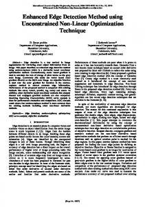
2 Channel Estimation in Frequency Domain Channel estimation is required for coherent detection in OFDM systems. Long training sequence is used to estimate the channel before start transmitting the data. Fig. 1 shows the frame structure of IEEE 802.11a physical layer.
Short training sequence
Long training sequence
t1 t2 t3 t4 t5 t6 t7 t8 t9 t10 GI2
T1
T2
Data
Data
GI SIGNAL GI DATA1 GI DATA2
Fig. 1. Frame structure of IEEE 802.11a physical layer
The long training sequence is a known data to receivers. When the known data xn passed through the channel, the received signal yn can be expressed as equation (1).
yn = xn * hn + wn
(1)
where hn is the impulse channel response, wn is AWGN, * symbol denotes convolution. Equation (1) becomes equation (2) in frequency domain.
Yk = X k H k + Wk ,
0 ≤ k ≤ N −1
(2)
From equation (2), the channel response can be estimated in frequency domain as equation (3).
Hˆ k = Yk / X k + Wk / X k ,
0 ≤ k ≤ N −1
(3)
A Study on the Enhanced Detection Method
677
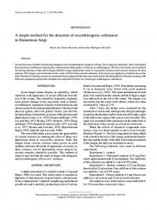
3 Proposed Channel Estimation Method by Impulse Signal Train The length of channel impulse response is much shorter than that of an OFDM symbol. Therefore, more than one channel impulse response can exist during one OFDM symbol. In this paper, impulse signal train in time domain is proposed as the training sequence for channel estimation. We consider IEEE 802.11a OFDM modem and assumed that the maximum impulse response length L = 16 and the sub-carrier number N = 64. Fig. 2 shows the conceptual block diagram of the proposed channel estimation method. impulse signal train
Proposed preamble sequence
IFFT
Estimated channel values
FFT
N
Multi-path fading+AWGN channel
Average and zero-padding L
(N-L) zero-padding
Fig. 2. The proposed channel estimation method
In the proposed method, one OFDM symbol period is equally divided into 4 sections. We designed a preamble sequence in frequency domain so that one impulse signal can be generated in each section. A total of 4 impulse signals exist in one training OFDM symbol as shown in Fig. 2. The proposed preamble signal in frequency domain can be expressed as equation (4).
⎧4, if n = 4k , k = 0,1, 2,...15 new _ preamble[n] = ⎨ otherwise ⎩0,
(4)
The time domain signal can be obtained by performing IFFT over the proposed preamble signal and be expressed as equation (5).
TS (n) = IFFT (new _ preamble[n]) = δ (n) + δ (n − L) + δ (n − 2 L) + δ (n − 3L),
0 ≤ n ≤ N −1
(5)
where δ (n) is unit impulse function which is one only when n = 0. TS(n) signal is an impulse signal train as shown in Fig. 3-(a). When the impulse signal train passed through a wireless multi-path channel, an example of the received signal is shown in Fig. 3-(c) and (d). It can be assumed that during one OFDM symbol the channel is invariant with time.
Relative Power
H.-G. Jeon et al.
Relative Power
678
0
16
32
48
0
Delay time[sample]
(a) Impulse signal train(Time domain)
16
32
48
Delay time[sample]
(b) Impulse response(multi-path)
(d) Impulse response(multi-path with AWGN) Fig. 3. Impulse response examples
Received signal r ( n) can be expressed as equation (6).
r (n) = TS (n) * h(n) + n(n)
(6)
A Study on the Enhanced Detection Method
679
where n(n) , h(n) , and * symbol denote AWGN noise, channel impulse response, and convolution operation, respectively. Equation (6) can be expressed as equation (7)
r ( n) = δ ( n ) * h ( n) + δ ( n − L ) * h ( n ) + δ ( n − 2 L ) * h ( n ) + δ ( n − 3 L ) * h ( n ) + n ( n ) = h( n) + h( n − L ) + h( n − 2 L ) + h( n − 3L ) + n( n )
(7)
We consider only a causal system. And the maximum channel response length is assumed to be L sample duration. In this case, h(n) = 0, if n < 0 or n > L − 1 . Therefore, from equation (7), it can be seen that a series of 4 channel responses with L sample interval are there. In the OFDM receiver, 4 received impulse signals can be regarded as an identical impulse channel response so that they are averaged to make one received impulse signal as expressed in equation (8). Additionally, the effect of AWGN noise is reduced by the averaging operation.
ha (n) =
1 3 ∑ r (n + iL) 4 i =0
= h(n) +
1 3 ∑ ni (n) , 4 i=0
0 ≤ n ≤ L −1
where ni ( n) = n(n + iL), i = 0,1, 2,3 . Each random process
(8)
ni (n) is independent and
has an identical probability distribution. Therefore, noise variance in equation (8) is reduced as much as 1/4 factor. That means an increased accuracy in the channel estimation. where h( n) is the channel response by the impulse signal train and ni ( n) is AWGN. Fig. 4 is an example of an averaged impulse response obtained by equation (8) under the condition of multi-path and AWGN of Fig 3-(d). In this paper, the maximum length of impulse channel response, L, is assumed to be 16. Therefore, the sample over the maximum length is set to be zero. The affection of AWGN in the channel estimation can be reduced by averaging the received impulse response signal. To make N point FFT (Fast Fourier Transform) and eliminate AWGN components included in (N-L) samples after the maximum impulse response length, (N-L) zeros are padded at the sample positions of more than L. The zero padded impulse response signal h% (n) is expressed as equation (9).
⎧ h ( n) , 0 ≤ n ≤ L − 1 h% (n) = ⎨ a , L ≤ n ≤ N −1 ⎩ 0
(9)
We can estimate the channel by performing FFT over the zero padded impulse response signal h% (n) as shown in equation (10).
H (k ) = FFT {h% (k )},
0 ≤ k ≤ N −1
(10)
In indoor environment, channel response length is shorter than that of outdoor environment. According to the channel response length, the zero padding length should be determined. How to determine the channel response length is beyond our topic. In this paper, we assume that L = 5 in indoor wireless channel and L = 16 in outdoor wireless channel.
H.-G. Jeon et al.
Relative Power
680
0 1 2 3 4 5 6 7 8 9
63
Delay time[sample]
Fig. 4. Impulse response with zero padding
4 Simulation In order to evaluate the performance of the proposed method, a computer simulation is carried out under the condition of multi-path with 3 paths. In indoor environment, Doppler frequency is set to 0 Hz, and maximum delay is assumed to be 4 samples. In outdoor environment, Doppler frequency is set to 200 Hz, and maximum delay is assumed to be 16 samples, considering the worst case. The simulation condition is described in table 1. The MMSE method is not considered in this simulation, because the method needs a prior knowledge about the channel to be estimated. AWGN Data Generation
S to P
QPSK modulation
Data mapping (DC=0)
Mux
IFFT
Add GI
Attenuation Calculation
Multipath Rayleigh 3-ray
FFT
Remove GI
Channel Estimation Data Generation
BER Calculation
P to S
QPSK demodulation
CE symbol Remove
Channel Estimation
Fig. 5. Simulation model block
zero padding
A Study on the Enhanced Detection Method
681
Fig. 5 shows the OFDM system model block for the simulation. In this simulation, we assumed a perfect synchronization in the OFDM system. The BER performance of the proposed method is compare with those of the long preamble method and the LS method. Table 1. Simulation parameters
Item
Value
Fading channel
Multipath Rayleigh fading channel(3ray)
Mean power
3-ray (0, 10, 20) dB 4-ray (0, 20, 10, 30) dB
Arrival time delay
3-ray (0, 2, 4) samples 4-ray (0, 2, 3, 4) samples
Modulation
QPSK
Doppler Frequency
0 Hz(indoor), 200Hz(outdoor)
Loop
10000
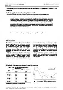
AWGN = 10dB, Doppler Frequency = 0Hz, 3-ray[0, 10, 20 dB] 1 0.9 0.8
Magnitude
0.7 0.6 0.5 0.4 0.3 Ideal channel Proposed channel estimation Impulse response estimation Long preamble(IEEE802.11a)
0.2 0.1 0 0
10
20
30
40
50
60
Index[sample]
Fig. 6. Comparison of channel estimation values
Fig. 6 shows the channel estimation results obtained by long preamble method, LS method, and the proposed method in indoor environment (L = 5). As we can see from Fig. 6, the proposed method is very close to the ideal channel estimation. When L is a small value (L