A super‐resolution algorithm for enhancement of FLASH LIDAR data Alexander Bulyshev*a, Michael Vanekb, Farzin Amzajerdianb, Diego Pierrottetc, Glen Hinesb, and Robert Reisseb a
b
AMA-inc, Hampton, Virginia 23666, NASA Langley Research Center, MS 468, Hampton, Virginia 23681-2199 c Coherent Applications, Inc., Hampton, Virginia 23666
ABSTRACT A novel method for enhancement of the spatial resolution of 3-diminsional Flash Lidar images is being proposed for generation of elevation maps of terrain from a moving platform. NASA recognizes the Flash LIDAR technology as an important tool for enabling safe and precision landing in future unmanned and crewed lunar and planetary missions. The ability of the Flash LIDAR to generate 3-dimensional maps of the landing site area during the final stages of the descent phase for detection of hazardous terrain features such as craters, rocks, and steep slopes is under study in the frame of the Autonomous Landing and Hazard Avoidance (ALHAT) project. Since single frames of existing FLASH LIDAR systems are not sufficient to build a map of entire landing site with acceptable spatial resolution and precision, a super-resolution approach utilizing multiple frames has been developed to overcome the instrument’s limitations. Performance of the super-resolution algorithm has been analyzed through a series of simulation runs obtained from a high fidelity Flash LIDAR model and a high resolution synthetic lunar elevation map. For each simulation run, a sequence of FLASH LIDAR frames are recorded and processed as the spacecraft descends toward the landing site. Simulations runs having different trajectory profiles and varying LIDAR look angles of the terrain are also analyzed. The results show that adequate levels of accuracy and precision are achieved for detecting hazardous terrain features and identifying safe areas of the landing site. Keywords: 3-D imaging, imaging LADAR, Flash Lidar, imaging laser radar, hazard detection, safe landing.
1. INTRODUCTION Super-resolution (SR) is the image enhancement technique which uses a set of shifted images of the same object to obtain the spatial resolution better then the pixel size of each individual image. Many SR algorithms for enhancing 2-D intensity images have developed over the past decades for different applications including satellite imagery1-4 . In lieu of emergence of FLASH LIDAR as a viable sensor for generation of 3-D images, some limited work has been conducted on application of SR technique to 3-D range images for a simple case of normal incident angle5-7.. A more practical SR method that applies to any incident angle was first proposed last year8. This paper provides some additional details on the SR algorithm developed by NASA and reports on the current state of its implementation. One of the particular problem which should be solved as the part of the SR problem is to determine the position and attitude of LIDAR relatively to known coordinate system. This problem can be solved by independent measurements or correlating images obtained from different positions and orientations of the LIDAR. The former is *
[email protected], phone: 1-757-864-9458, fax: 1-757-864-8828.
not always available, so the latter is the only real option. At the same time this approach has obvious limitation: it works only if the correlation between two frames is high. There are several efficient methods to find relative position of the imaging system or the position of the individual frame on the general image. Most of those methods are applied effectively in 2D case, but they will be computationally excessive for the 3D case beyond the practical limit. In the current work we propose to generalize Lucas-Kanade9 method to work in full scale 6 dimensions state vector space. The computational complexity of this method is proportional to the dimension of the state vector space, so the increase of the computational time from 2D to 6D is tolerable. The paper is organized as following. Section 2 is serving to describe Flash Lidar model which is used in computer experiments. Section 3 devoted to the general description of 3D super-resolution algorithm. Section 4 describes iterative approach on one step of the super-resolution scheme. Section 5 is devoted to the back projection method. Section 6 contains the results of computer modeling followed by the conclusions.
2. SUPER-RESOLUTION (3D APPROACH) The SR algorithm being developed by NASA is to achieve two major objectives: creating a Digital Elevation Map (DEM) covering a sufficiently large area with acceptable accuracy and precision, and retrieving the relative vehicle trajectory. Starting with first frame, the stationary high resolution grid is created. The algorithm utilizes an iterative scheme which updates the DEM in a high resolution grid and finds the next trajectory point using one Lidar frame at a time. That makes the algorithm computationally efficient and opens the possibility for real time processing. A back projection algorithm is used for the DEM creation and 6-d generalization of Lucas-Kanade method is utilized to retrieve the trajectory of the space craft and Lidar attitude. There are two different, but connected problems should be solved: 1) registration of each individual image to the high resolution elevation map,and2) transfer of each lidar pixel range data to the high resolution elevation map. If the first problem can be solved independently, the overall problem is much less complicated. The image registration is solved by analyzing consecutive images shifted relative to each other. In our case both problems are significantly more complicated. First, the registration problem becomes 6 dimensional since the total state vector of the Flash Lidar need to be determined. Second, the exact solution of the super-resolution problem with the location and orientation of the Flash lidar both known leads to the solution of the 3D integral equation which is computationally complicated. In order to solve the registration problem (, also referred to as the ortho-rectification problem), we propose to use generalize Luke-Kanade method9. The second problem – translating the lidar range data to elevation data – will be solved by using a back projection method developed by authors earlier and described in reference 8.
from the Lidar FPA to the points
One frame of the Flash Lidar data will be described as the 2D set of ranges Ri , j
on the reflecting surface. i, j are the numbers of the row and column consequently. The super-resolution method using Flash Lidar data can be represented as the sequence of the following steps: i.
Chose the spatial domain and create of the fine grid for the high resolution map.
ii.
Chose the coordinate system associated with the instrument.
iii.
Chose initial value of the state vector.
iv.
Using the first frame, generate the first approximation of the map applying the back projection method.
v.
Using the next frame and the map determine the corresponding value of the state vector.
vi.
Update the map using the current frame and obtained value of the state vector.
vii.
Check if there is another frame available and then go to the step #v. Otherwise the process is concluded.
viii.
Convert the obtained map from the instrument coordinate system to the ground coordinate system.
The spatial domain and the fine grid on this domain are stationary during the process. If there is no additional information about the Flash Lidar state vector in any ground based coordinate system, then the map can only be reconstructed in the instrument or the platform coordinate system. We assume that the transformation from coordinate system to another can be done easily. The following notations will be used in the mathematical description of the algorithm:
is the domain on the X-Y plane where the map will be constructed
is the rectangular fine mesh with i and j denoting the nodes numbers ij
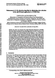
X 0 , Y0 , Z 0 is the initial coordinates of the Lidar , , are three angles which describes the pointing vector of the Flash lidar (see. Fig 1) V X , Y , Z , , , is state vector for the Lidar
h hij is the elevation map defined on the nodes of the fine mesh ij R Rij is the set of ranges.
Detector Surface R(x,y)
Elevation
(x,y) Figure 1: FOV of one detector
3. ITERATIVE SCHEME As was described in the previous section, the set of ranges can be presented as the functional of the state vector and elevation map:
R h ,V
(1)
Knowing the state vector, it is possible to invert equation (1) and obtain some approximation for the digital elevation map (DEM). If only one frame is used, then the spatial resolution of this approximation will be limited by size of the one detector projection on the ground. This approximation can be denoted as:
hbp bp V , R
(2)
where subscript “bp” stands for back projection. In order to start the iterative process described previously, the initial value of DEM should be defined. We propose to use the frame #1 for this purpose:
h 0 bp V0 , R0
(3)
Solving equation (1) in the respect of V gives us the position of the Lidar corresponding to the frame #1. That allows us to update the elevation map, and the process can go on after that.
4. Back projection method The back projection method we use in the current investigation is described previously in details. The term “back projection” originally came from linear X rays tomography, where measured signals are 1D (2D) projections of 2D (3D) object. Calculation of projections is the direct problem solving. It is actually integration of the object quantity feature (density for example) along with the X ray path. The reconstruction technique ( inverse problem solving), when the property of projections are translated back into the object following the X ray path in the inverse direction is called back projection. In case of the Flash Lidar, a similar concept can be applied.
5. NUMERICAL IMPLEMENTATION In order to prove the concept and to test the algorithm, a computer code in Matlab language was developed. The block diagram of this code is presented in Fig 2.
Figure 2: Block diagram of the computer code implemented super-resolution method
The function of each block is described below:
Input frame is the 2D array of ranges with dimensions 128X128
Initialization block creates initial values of the state vector and computational domain
Back projection block converts a frame of ranges into a map defined on the fine mesh
First back projection works only for the first frame, for the rest of the frames it will be skipped
Trajectory correction calculates the next values of the state vector based on the next frame and the current map
Back projection updates the map
Output map is the result of the processing of all of the frames
6. NUMERICAL SIMULATION Using the Matlab codes described above, a set of computational experiments was performed. There were two major goals for these experiments, one to test the SR algorithm in generation of high resolution elevation map, and two to test its trajectory restoration capability. For these computer experiments, we used the ALHAT project terrain and trajectory models 12. A section of the lunar surface was chosen to create a simulated map, which was considered as the truth map. The descending trajectory of the spacecraft and Lidar pointing direction was also simulated. Then, a set of Lidar frames was calculated using direct problem solver (see above). Applying the SR procedure described above, the DEM and the vehicle trajectory were restored and compared with “truth” map and trajectory. Approach angles, field of view (FOV), measurements errors, and numerical schematic parameters were varied. The most important and critical parameter which influences the results of the
map restoration and the trajectory retrieval is the approach angle. One of the results of computer modeling for challenging case of shallow approach angle is presented below. The original map was chosen from a synthetic lunar terrain database in an end-to-end engineering landing simulation known as POST II (Program to Optimize Simulated Trajectories II)13. The map is classified as a smooth mare terrain type with 10% rock abundance. The original elevation map, shown in Figure 3a), was generated on a rectangular grid with 1024 × 1024 pixels. Lidar data were generated using 30 degree approach trajectory starting with a slant range of 1000 m and descending down to 100 m. Flash frames were taken every 1.0 m of descent. The sizes of the frames were 128×128 pixels. The footprint of the first frame, which was captured at 1000 m range, has the smaller size than the original map. The original and restored elevation maps are presented in Fig 3.
Figure 3: The original and restored elevation maps in meters
The trajectory of the Lidar was also restored using 30 frames. The errors of restoration for all 3 coordinates are presented in Fig 4. All errors are in submeter area.
Figure 4: The differences (in m) between ideal and restored trajectories for X, Y, and Z coordinates
7. CONCLUSION A new method of Flash Lidar image enhancement together with the Flash Lidar trajectory and attitude reconstruction is introduced. The capability of the approach to restore a high resolution elevation map using a series of low resolution images generated by a Flash Lidar is demonstrated through a number of computational experiments.
REFERENCES
1. S. Park, M. K. Park, and M. Kang, “Superresolution image reconstruction: A technical review,” IEEE Signal processing Magazine 20, pp. 21–36, May 2003.
2. S. Farsiu, M. D. Robinson, M. Eland, and P. Malinfar, “Fast and robust multiframe superresolution,” IEEE Transactions on Image Processing 13, pp. 1327–1344, 2004.
3. G. Clement, J. Huttunen, and K. Hynynen, “Super-resolution image reconstruction from a sequence of aliased imagery,” Journal of the Acoustical Society of America 118, pp. 3953–3960, 2005.
4. S. Chaundhuri, Super-resolution Imaging, Springer, 2001. 5. Q. Yang, R. Yang, J. Davis, and D. Nister, “Spatial-depth super resolution for range images,” in IEEE Conference on Computer Vision and Pattern Recognition, 2007.
6. G. Rosenbush, T. Hong, and R. Eastman, “Super-resolution enhancement of flash LADAR range data,” in Proceedings of SPIE, 6736, 2007.
7. S. Hu, S. S. Young, T. Hong, J. Reynolds, K. Krapels, B. Miller, J. Thomas, and O. Nguyen, “Superresolution for flash LADAR data,” Applied Optics 49(5), pp. 772–780, 2010.
8. A. Bulyshev, G. Hines, M. Vanek, F. Amzajerdian, R. Reisse, D. Pierrottet, “Super Resolution Image Enhancement for a Flash Lidar: Back Projection Method,” in Proceedings of SPIE, Orlando, 2010. 9. Lucas B D and Kanade T 1981, An iterative image registration technique with an application to stereo vision. Proceedings of Imaging understanding workshop, pp 121—130 10. Dahlquist G and Bjorck A 1974, Numerical Methods, Prentice Hall, 572p. 11. A. Bulyshev, D. Pierrottet, F. Amzajerdian, G. Busch, M. Vanek, and R. Reisse, “Processing of 3-dimensional flash lidar terrain images generated from an airborne platform,” Proc. of SPIE, 2009, Vol. 7329 73290I-9. 12. C. Epp, E. Robinson, and T. Brady, “Autonomous landing and hazard avoidance technology (ALHAT),” in IEEE Aerospace Conference, pp. 1–7, 2008. 13. J. Davis, S. Striepe, R. Maddock, G. Hines, S. Paschall, B. Cohanim, T. Fill, M. Johnson, B. R., K. DeMars, R. Sostaric, and A. Johnson, “Advances in POST2 end-to-end descent and landing simulation for the ALHAT project,” in AIAA/AAS Astrodynamics Specialist Conference, AIAA-2008-6938, 2008.