1548
IEEE JOURNAL OF SELECTED TOPICS IN SIGNAL PROCESSING, VOL. 9, NO. 8, DECEMBER 2015
A Superresolution Wide Null Beamformer for Undersampled Signal Reconstruction in SIMO SAR Karen Mak, Student Member, IEEE, and Athanassios Manikas, Senior Member, IEEE
Abstract—With single-input single-output (SISO) SAR systems, employing a single transmitter and receiver beam, there exists a high resolution, wide swath contradiction. However, by using multiple receiver beams and employing array processing techniques, this contradiction can be overcome, allowing greater flexibility and a wider range of application requirements to be met. In this paper the use of single-input multiple-output (SIMO) SAR systems for overcoming this contradiction is of interest, and a novel beamformer is proposed for processing in the cross-range direction. In order to fully describe the system, the array manifold vector is utilized, which is a key concept in the design of the beamformer. In particular, this beamformer is a superresolution beamformer capable of forming wide nulls using subspace based approaches and allows the suppression of ambiguities in multiple sets of received undersampled SAR data in the cross-range direction and reconstruction of the Doppler spectrum to form a single unambiguous set of SAR data. Compared to the existing reconstruction algorithm, only a single weighting vector is required for a block of ambiguous Doppler frequencies compared to a weight vector required for each ambiguous Doppler frequency. The capabilities of the proposed beamformer are shown to give an improved performance in ambiguity suppression via computer simulation studies in a representative maritime environment. Index Terms—Single-input multiple-output (SIMO) synthetic aperture radar (SAR), array manifold vector, array processing.
NOTATION
I. INTRODUCTION
S
ELECTION of the Pulse Repetition Frequency (PRF), , of a SAR system plays an important role in preventing range and cross-range ambiguities. For a SISO SAR system, a single beam is employed for transmitting and receiving. In this paper, it is assumed that planar arrays are used to form the required directional beam using beamforming. However other systems, for example a reflector phased array or horn antenna, can be used. The following condition needs to be met to ensure unambiguous returns are received [1] (1) where is the speed of light, is the swath width, is the incident angle and is the Doppler bandwidth defined as the range of Doppler frequencies in the cross-range direction in the antenna footprint [2]. From (1), the condition on the left hand side must be satisfied to prevent cross-range ambiguities by ensuring is greater than . However, cannot be made arbitrarily large, as range ambiguities will occur due to the returns from different transmitted signals overlapping and being received within the same time frame, thus the right hand side of (1) must also be satisfied. For non-zero squint, is calculated as [2]
Scalar
(2)
Column vector Matrix identity matrix vector of ones
is the squint angle. where In the case of zero squint, i.e., is given as [2], [3]
(boresight direction), (3)
vector of zeros Transpose, conjugate transpose Diagonal matrix whose diagonal entries the elements of Kronecker product
where Using (3), (1) becomes
Hadamard (element-by-element) product Manuscript received January 29, 2015; revised June 21, 2015; accepted July 21, 2015. Date of publication August 06, 2015; date of current version November 17, 2015. The guest editor coordinating the review of this manuscript and approving it for publication was Dr. Yuri Abramovich. The authors are with the Department of Electrical and Electronic Engineering, Imperial College London, London SW7 2AZ, U.K. (e-mail:
[email protected];
[email protected]). Color versions of one or more of the figures in this paper are available online at http://ieeexplore.ieee.org. Digital Object Identifier 10.1109/JSTSP.2015.2465308
(4) thus relating the parameters and , indicating that for a fixed value of , an increase in will lead to coarser resolution and vice versa, thus showing that it is not possible to increase both and simultaneously resulting in a wide swath, high resolution contradiction. However in recent years in the field of SAR, there has been considerable interest in so-called multi-channel SAR systems using an array of beamformers and Smart Multi Aperture Radar
1932-4553 © 2015 IEEE. Translations and content mining are permitted for academic research only. Personal use is also permitted, but republication/ redistribution requires IEEE permission. See http://www.ieee.org/publications_standards/publications/rights/index.html for more information.
MAK AND MANIKAS: SUPERRESOLUTION WIDE NULL BEAMFORMER FOR UNDERSAMPLED SIGNAL RECONSTRUCTION IN SIMO SAR
Techniques (SMART) SAR systems using an array of beamformers with additional digital beamforming [3]–[6] These allow the above contradiction to be overcome. Of particular interest in this paper are SAR systems with a single transmit beamformer and multiple receive beamformers, which will be referred to as SIMO SAR systems. In this paper, array processing concepts in communications are applied to SIMO SAR systems, where the aim is to achieve undersampled signal reconstruction. Inspired by the non-uniform displaced phase center sampling algorithm or reconstruction algorithm in [7], shown to be equivalent to null steering in [3], referred to here as the steering vector beamformer, and the superresolution beamformer in [8] for communication systems, a novel superresolution wide null beamformer is proposed for SIMO SAR systems for the reconstruction of the multiple sets of received undersampled signals. The novelty of this algorithm is in the ability to form wide nulls for signal reconstruction and therefore allows the use of a single weight vector for each block of ambiguous Doppler frequencies compared to the existing reconstruction algorithm using a single weight vector for each ambiguous Doppler frequency. As resolution increases as a function of increased aperture length, the proposed beamformer of this SIMO SAR system uses a large aperture, and consequently has increased resolution. Furthermore, the proposed wide null beamformer is also a “subspace” type and thus has infinite (asymptotically) resolution capabilities [9]. Beamforming techniques for SAR systems are first discussed in Section II, before the mathematical modeling of the received signals used throughout this paper is presented in Section III. In particular the modeling of the received signals utilizes the array manifold vector, which is a key concept for the description of the proposed wide null beamformer. Then the proposed beamformer for the formation of wide nulls applied in the Doppler frequency domain for undersampled SAR data reconstruction is presented in Section IV. Representative results are then given in Section V, firstly in a high Signal-to-Noise (SNR) case to allow a better analysis of the capabilities of the proposed beamformer using impulse response cuts of an imaged target. Then a low SNR case with added sea clutter is used for a representative application of the beamformer in a maritime application before this paper concludes in Section VI. II. BEAMFORMING FOR SAR SYSTEMS Beamforming algorithms based on subspace techniques are treated extensively in radar applications [10]–[15]. However, with conventional SAR systems employing a single transmit and receive beamformer, referred to here as SISO SAR systems, there is a limitation on the ability to directly apply beamforming algorithms based on subspace techniques [16] due to the need for multiple spatial channels in order to calculate the required covariance matrix. However, by using overlapping subsets of data from a SISO SAR system, subspace techniques can be used to generate higher resolution SAR images [17]. However in recent years, there has been considerable interest in so-called multi-channel SAR systems using an array of beamformers and Smart Multi Aperture Radar Techniques (SMART) SAR systems using an array of beamformers with additional digital beamforming [6]. Applications of these systems include
1549
jammer suppression using Space-Time Adaptive Processing (STAP) [18] and clutter suppression. One key area where these systems can be used is in wide swath, high resolution imaging. In the case where a multi-channel SAR system with a single transmit beamformer and receive beamformers is utilized, referred to here as SIMO SAR systems and with , the single transmit beamformer transmits a chirp signal of duration seconds, every seconds, resulting in the chirp signal being transmitted a total of times along the flight path. Therefore, due to the design of a SIMO SAR system, received sets of signals for every transmitted chirp are received, resulting in a total of samples in the cross-range direction compared to only samples in the case when a SISO SAR system is used. These additional samples allows (1) to be rewritten for a SIMO SAR system, giving (5) where in comparison to a SISO SAR system 1) in a SIMO SAR system, can be decreased times while still satisfying (5), resulting in the ability to image a wider swath unambiguously. 2) in a SIMO SAR system, for the same value of , a larger can be used while still satisfying (5), which results in an improved cross-range resolution, as can be seen from (3). In this paper, point 1 is of interest, where is decreased for each receiver such that (1) is not satisfied, resulting in crossrange ambiguities due to undersampling, while allowing the required wide swath width to be imaged. If beamformers in the cross-range direction are used, (5) can be satisfied, and suppression of these ambiguities or aliases, which correspond to ambiguous Doppler frequencies, can be achieved using array processing techniques to reconstruct a single unaliased output, therefore allowing wide swath, high resolution imaging, compared to SISO SAR systems. One particular technique to achieve this is the non-uniform displaced phase center sampling algorithm in [7] which, as mentioned in [3], is equivalent to null-steering using the steering vector beamformer, and is given in Appendix A with the notation used throughout this paper. The use of the steering vector beamformer allows the formation of multiple sharp nulls for ambiguous Doppler frequency suppression. However, there are no known examples of using wide nulls for undersampled SAR signal reconstruction in the SAR literature. For this application, the use of wide nulls will allow the suppression of a range of ambiguous Doppler frequencies using a single wide null, compared to multiple sharp nulls. To achieve this, a novel superresolution wide null beamformer for SIMO SAR systems, inspired by the existing non-uniform displaced phase center sampling algorithm in [7] and the superresolution beamformer in [8] for communication systems, is proposed in Section IV. III. SIMO SAR SYSTEM MODEL A. SIMO SAR Mathematical Modelling Consider a SIMO SAR system represented in Fig. 1, consisting of a transmitter formed from a planar array of antenna
1550
IEEE JOURNAL OF SELECTED TOPICS IN SIGNAL PROCESSING, VOL. 9, NO. 8, DECEMBER 2015
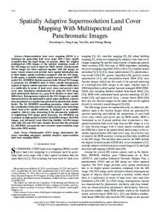
Fig. 1. SIMO SAR system geometry. Note: The Doppler frequency term is only required in a satellite SAR case and when “stop and receive” data collection is not assumed.
elements, which travels along a straight path in the along track direction. The elements are located on the same platform and have Cartesian coordinates described by the matrix
scatterers, the receives the echoes. By assuming a total of ceived signal at a particular time can be modeled as a vector , given as
(6a)
(10)
(6b) where and are column vectors with the and coordinates of each transmitter element respectively and denotes the location of the element of the array. Each of the receive beamformers is also formed using an array of elements and travels in the direction along the positive axis, resulting in a total of antenna elements, which have Cartesian coordinates described by the matrix
with transmitted at
and is received at
(7) where of the
denotes the Cartesian coordinates of the beamformer defined as
elements (8) and
with
and being column vectors containing the and coordinates of each element of the beamformer respectively. All elements of each receive beamformer are located on the same platform, however, the receive beamformers may either be located on the same or separate platforms. The transmitter, described by the complex vector , produces a single beam and transmits a chirp pulse (9)
where is the chirp bandwidth and the chirp pulse duration, with defining the chirp rate. The scatterers within this beam footprint are illuminated for seconds and all elements of the SIMO SAR system re-
with
, where a chirp
MAK AND MANIKAS: SUPERRESOLUTION WIDE NULL BEAMFORMER FOR UNDERSAMPLED SIGNAL RECONSTRUCTION IN SIMO SAR
The complex vector manifold vector associated with the
is the transmitter array scatterer described as (11a)
(11b)
1551
where the required data collection mode determines the time dependency on . Examples of data collection modes include Stripmap, ScanSAR, Spotlight, and TOPSAR (Terrain Observation by Progressive Scans). Likewise, the elements of the system forming the receive beamformers are weighted such that beams are formed to receive the scatterer echoes. The weight matrix is described by
with .. .
.. .
..
.
.. .
(19)
(12) where is the reference slant range between the SAR system and the scatterer, is the path loss exponent and is the wavenumber vector given as (13a) (13b) is a unit vector pointing in the direction of the scatterer. Similarly the complex vector is the rescatterer ceiver array manifold vector associated with the described as
and
(14a)
where is an vector of the weights of the elements of the beamformer at time given by (20) Due to the assumption that the antenna elements forming a single beam are collocated, the round trip delay between the scatterer can be described by . elements and the However, all groups of elements may not be collocated and may be located on different platforms. Therefore the round trip delays will differ. As a result, it can be described by the vector given as
(21a)
(14b) (21b)
with
(15) and is due to and where the difference in signs in the opposite flow of energy between transmitting and receiving. In the case when the scatterer is located in the far field of the beamformer, i.e., is much greater than the array's real aperture, (11) and (14) reduce to the plane wave propagation manifold vector expressed as
where and are the slant ranges between the transmit beamformer and the scatterer and the receive beamformer and scatterer. Furthermore and are the differences between and with the reference slant range for and , and where a chirp signal transmitted at time is received at time . The receiver array output can then be modeled as
(16) and (17) Using the manifold vector, the weight vector , given in (18) is designed such that a single beam is formed whose mainlobe points in the direction for all , with , where and are the azimuth and elevation angles between the center of the beam footprint on the ground respectively (18)
(22) with and , where a chirp , transmitted at is received at and where the element of corresponds to the signals received by the receive beamformer and is now a vector of round trip delays associated with the scatterer and beamformers and
1552
Fig. 2. 3D datacube of the received signals at all SAR system after discretisation.
IEEE JOURNAL OF SELECTED TOPICS IN SIGNAL PROCESSING, VOL. 9, NO. 8, DECEMBER 2015
elements of the SIMO
Fig. 3. The outputs of the range direction.
receive beamformers after discretisation in the
where
(25)
When all receivers are on the same platform, planewave propagation can be assumed, but when they are located on different platforms, the spherical wave propagation manifold vector should be utilized. However, the elements of the manifold vector that are on the same platform will have approximately equal ranges thus collapsing to the planewave propagation manifold vector. B. Discrete Time Modelling The received signals at the array elements of the SIMO SAR system are sampled at a sampling rate of to obtain samples and the discrete samples can be represented by a 3D datacube, shown in Fig. 2, where is a matrix describing the data received at all elements of the SIMO SAR system, given as (23) with being the sample of the vector at time . is a matrix describing the data received at all antenna elements at a particular sample at . Weights are then designed and applied to all elements to form outputs, i.e., beams, resulting in a datacube, as shown in Fig. 3. Here is an matrix containing all the data received by the beamformer from all transmitted chirp pulses and matrix is a matrix describing the data received by the beamformers and is modeled as
The matrix describes the data received by the array of receivers at a particular range sample at and can be seen as a range sample spacetime snapshot. Similarly can be seen as a cross-range sample spacetime snapshot, with the pulse being analogous to the cross range sample. IV. SUPERRESOLUTION WIDE NULL BEAMFORMING Aliasing of the spectrum of the received signals in the crossrange direction occurs due to undersampling when (1) is not satisfied. Therefore suppression of the ambiguities is required in order to allow the reconstruction of the full Doppler spectrum over the frequencies to , where each beamformer receiver receives a section of the Doppler bandwidth. For the this is defined as being over the range [3] (26)
(24)
for
.
MAK AND MANIKAS: SUPERRESOLUTION WIDE NULL BEAMFORMER FOR UNDERSAMPLED SIGNAL RECONSTRUCTION IN SIMO SAR
1553
where is a vector of the coordinates of the center element of the beamformers at time and is the slant range to the center of the beam footprint and (30) By forming the
matrix (31)
where condition
is the
eigenvector of
, with
satisfying the (32)
Fig. 4. Representation of suppression of subbands, where the dark grey subbands are desired.
Fig. 4 gives a representation of these frequency ranges, defined as subbands, where the aim is to reconstruct the full Doppler frequency range from to . By identifying the desired subbands, shown in dark grey in Fig. 4, and suppressing all other ambiguous subbands, reconstruction using array processing techniques is possible, where for the receiver beamformer, the ambiguous Doppler frequencies for , with . With reference cover all to Fig. 4, it can be seen that a wide null could be designed such that ambiguous subbands is suppressed at a time. In this case, only up to two wide nulls need to be formed at a time without suppressing the desired subband, where two nulls, , are required when and only one null, , . is required if By first considering the formation of a single wide null, the matrix for the ambiguous Doppler frequency range can be calculated as
is the eigenvalue of and is a where defined threshold in dBs giving the level of suppression1, and then calculating its complement projection to give (33) a
weight vector is formed, such that after performing a wide null is formed over the Doppler frequency range . is the manifold vector at the desired Doppler frequency assumed to be the center Doppler frequency of the desired subband2, and is calculated as (34) for the beamformer, with . wide nulls are required, the In the general case where above technique can be extended by forming the matrix (35) to give the reand calculating its complement projection quired weights, which when normalized is given as
(27) (36) for which can be seen as the summation of all within the range , with being the manifold vector in terms of Doppler frequency, described by (29) where the subscript is used here to indicate the Doppler frequency at which the manifold vector is calculated at is to be suppressed. As it is assumed that the receive beamformers form a linear array along the positive axis and (28a)
By evaluating the required weight vector for all subbands, the reconstructed data can be represented as (37) where
for
and
(28b) being the squint angle, the manifold vector can with be represented in terms of Doppler frequency and simplified to give
(29)
.. .
(38)
1Note that the value can take is also limited by the number of receive beamvalues can take. Likeformers. With beamformers, there are only possible values of . The effect of on wise this results in only and selection is discussed in Appendix B. 2This results in the center of the mainlobe of the beamformer to be at the center Doppler frequency of the desired subband and therefore resulting in a symmetrical response.
1554
IEEE JOURNAL OF SELECTED TOPICS IN SIGNAL PROCESSING, VOL. 9, NO. 8, DECEMBER 2015
where is the data at the range line in the range Doppler domain and is the required weight vector for suppression of subband for . all subbands other than the As mentioned in [3], when the receivers are sparsely located in space, the increased separation between the transmitter and receiver may need to be taken into account with additional phase terms. In the case of , these extra terms can be combined with the calculated weights as follows (39) . where Also, due to an increased distance between the receivers, the range history of a single scatterer can no longer be assumed apreceivers. Therefore this difference proximately equal at all in range history between receivers needs to be compensated. In order to compensate for this, a range shift must be applied before the superresolution beamformer to ensure that the range history of the imaged scatterers are approximately similar in all sets of data. From [3], a shift related to distances between each receive beamformer and a reference slant range can be applied. By assuming the center element of the first beamformer of the array of beamformers is the reference, the required shift required beamformer can be applied using (40) and (41). for the
ALGORITHM SUMMARY 1) Apply range compression onto the sets of data: , which when stacked to form a datacube, allows the matrix to be extracted for all Doppler frequencies, where is (see Fig. 3) in the Doppler frequency domain. 2) Ensure that the processed sets of data are in the rangeDoppler domain. In the case where a sparse array of receiver beamformers is used, apply additional compensation to ensure that the range histories of the same target between the sets of received data are approximately equal using (40).
3) Identify the range of frequencies within all subbands using (26). 4) Identify the center Doppler frequency of all subbands using (26), and for the desired subband form the manifold vector, for the desired Doppler frequency, which is assumed to be the center Doppler frequency of the desired band. 5) For the formation of a wide null, identify the ambiguous Doppler frequencies to be suppressed, where for the receiver's data, the ambiguous Doppler frequency ranges are calculated from (26) for . Form the manifold vector for each wide null and find the most significant eigenvalues, , from the matrix using (27) and form the matrix using (35). 6) Form the weight vector , for using (36) and if required, apply extra phase terms to take into account sparse arrays. 7) Apply the weights, , to formed using (38), to obtain the reconstructed data using (37). 8) Continue with any further steps in the image formation algorithm of choice to form a single focused image with reduced cross-range ambiguities. V. RESULTS In this section, the performance of the proposed superresolution beamformer will be analyzed for a collocated array of receiver beamformers such that it can be assumed the range histories of imaged targets of interest are approximately equal between the sets of received data. The superresolution beamformer is integrated into the Chirp Scaling Algorithm to form a focused image from the sets of undersampled received data. Based on typical airborne parameters given in [19], the simulation parameters in Table I are used3, where has been chosen as this is a common SIMO SAR system configuration and examples of the application of beamforming for the suppression of cross-range ambiguities in existing systems are available [20], [21]. To show the capabilities of the proposed beamformer, two cases will be presented: 1) A high SNR case of 30 dB, where . Although this will not be true in practice, this will allow better analysis of the resulting Impulse Response Functions (IRF) of the imaged target and capabilities of the proposed beamformer without the target's alias being ‘covered’ by noise and surrounding clutter. 2) A low SNR case of dB, where with sea clutter. This will allow the capabilities of the proposed 3The designed parameters provide a trade-off between simulation time and actual airborne SAR imaging geometry parameters.
(40) (41)
MAK AND MANIKAS: SUPERRESOLUTION WIDE NULL BEAMFORMER FOR UNDERSAMPLED SIGNAL RECONSTRUCTION IN SIMO SAR
1555
TABLE I SIMULATION PARAMETERS FOR UNDERSAMPLING RECONSTRUCTION
TABLE II IMAGED TARGET PARAMETERS AND IMAGE SAMPLE LOCATIONS
Fig. 6. Log slant range cut of reconstructed image using steering vector beamformer.
Fig. 7. Log slant range cut of reconstructed image using proposed wide null beamformer.
A. Case 1:
With no Clutter
In this case a single target is simulated with parameters given in Table II and with added noise in the imaging environment at a high SNR of 30 dB to better illustrate the effect of proposed beamformer before and after processing and to show the location of the ambiguities to be suppressed. By plotting cuts at a specific slant range sample number, i.e., range gate corresponding to the target in the formed SAR image, the Impulse Response Function (IRF) of the imaged target can be analyzed. As undersampled raw data is used, it is important to know the location of the ambiguous returns of a particular target in the image space. These locations are related to the PRF time given as [19] Fig. 5. Log slant range cut of image from undersampled received data.
beamformer to be seen from the formed image after beamforming in a representative maritime environment. In both cases the proposed wide null beamformer performance will be compared and analyzed with the steering vector beamformer detailed in Appendix A. As mentioned in [3], in the case of collocated beamformers, the steering vector beamformer is equivalent to the non-uniform displaced phase center sampling technique described in [7].
(42) Due to the sampling in the cross range direction by , the ambiguous returns will occur at samples which are integer multiples of to the left and right of the actual target response. With reference to Fig. 5, which is a slant range cut of the focused image of the undersampled raw data received at beamformer 1, it can be seen that although a single target was imaged, its ambiguous return is clearly visible samples away from the actual target return. The peak-to-ambiguity ratio, i.e., the ratio
1556
IEEE JOURNAL OF SELECTED TOPICS IN SIGNAL PROCESSING, VOL. 9, NO. 8, DECEMBER 2015
TABLE III IMAGED TARGET PARAMETERS AND IMAGE SAMPLE LOCATIONS
Fig. 9. Focused image from undersampled received data.
Fig. 8. Focused image, using a single receive beamformer, of imaged targets with locations given in Table III, when no undersampling occurs.
of the actual target return and its ambiguous replica is about 15.4 dB. However, by making use of the sets of undersampled data, the steering vector beamformer described in Appendix A allows suppression of the ambiguous returns and reconstruction of the two sets of undersampled data. The improvement can be seen in Fig. 6, where although the ambiguous replica is still present, its response has been suppressed, increasing the peak-to-ambiguity ratio from 15.4 dB to about 25.4 dB. However, in a practical scenario this ambiguity
response may be ‘covered’ by noise and surrounding clutter and therefore may not be visible in the formed SAR image. Instead of the steering vector beamformer, the use of the proposed wide null beamformer applied to the sets of undersampled data results in Fig. 7. Like the case when the steering vector beamformer is applied, the ambiguous replica is suppressed but still present. However, in practical scenarios the replica may be ‘covered’ by noise and surrounding clutter making it less visible in the formed SAR image. Here there is an improvement in the peak-to-ambiguity ratio from 25.4 dB to about 33.8 dB compared to the steering vector beamformer. The 3 dB width of the target's IRF, i.e., cross-range resolution, in both the steering vector beamformer and proposed beamformer is also improved compared to when no reconstruction
MAK AND MANIKAS: SUPERRESOLUTION WIDE NULL BEAMFORMER FOR UNDERSAMPLED SIGNAL RECONSTRUCTION IN SIMO SAR
Fig. 10. Log slant range cut of image formed from undersampled received data across targets 3 and 4.
1557
Fig. 12. Log slant range cut of reconstructed image across targets 3 and 4 using steering vector beamformer.
Fig. 13. Focused image after reconstruction using proposed beamformer. Fig. 11. Focused image after reconstruction using the steering vector beamformer.
is performed. From the undersampled data, the 3 dB width is 1.30 m. However when the steering vector beamformer is applied, this is improved to 0.32 m. When the proposed wide null beamformer is applied slight widening occurs resulting in a 3 dB width of 0.35 m compared to the steering vector beamformer.
B. Case 2:
With Sea Clutter
In this case an imaging environment with added sea clutter dB, is simulated with targets, and a low SNR of whose parameters are given in Table III and are shown in Fig. 8. Fig. 9 shows the focused image of undersampled raw data and the ambiguous returns of the eight targets are clearly visible. With reference to Fig. 10, a slant range cut across targets 3 and 4 shows that the peak-to-ambiguity ratio is about 14.1 dB.
1558
IEEE JOURNAL OF SELECTED TOPICS IN SIGNAL PROCESSING, VOL. 9, NO. 8, DECEMBER 2015
APPENDIX A THE STEERING VECTOR BEAMFORMER The technique detailed in [7] allows the reconstruction of the complete Doppler bandwidth from aliased subsampled signals received by a SIMO SAR system. As mentioned in [3], in the case of collocated beamformers, this technique is equivalent to null-steering using the steering vector beamformer, where a manifold vector for all Doppler frequencies in the range , described in (26) for , is formed, such that (43) column of , is the manifold vector where the corresponding to the beamformers for the frequency range. The following weight matrix (44a) Fig. 14. Log slant range cut of reconstructed image across targets 3 and 4 using proposed beamformer.
By now performing reconstruction using the steering vector beamformer to give Fig. 11, it can be seen that the surrounding background of the targets is darker than in Fig. 9. Note that all images have been normalized and this darker background suggests a higher SNR. This can be seen in Fig. 12, showing a slant range cut across targets 3 and 4, where the noise level is about 10 dB, compared to around 25 dB in Fig. 10. Also from Fig. 12, it can be seen that there is an over 10 dB improvement in the peak-to-ambiguity ratio compared to when no reconstruction is applied, as shown in Fig. 10. By now performing reconstruction using the proposed wide null beamformer, Fig. 13 is obtained. With reference to Fig. 14 it can also be seen that the peak-to-ambiguity ratio is improved from 24.4 dB when using the steering vector beamformer to 29.5 dB when using the proposed beamformer.
(44b) is a weight can then be formed such that the vector vector which recovers the Doppler frequencies within the Doppler frequency range while suppressing the frequencies within the other frequency ranges. For the suppression of the ambiguous Doppler frequencies to form sets of unambiguous data for each Doppler frequency range and combination to form a single set of data for each Doppler frequency range, the row of is applied to the received signals at the receive beamformer in the Doppler domain4. The full Doppler spectrum can then be obtained by concatenating each Doppler frequency range, which results in unambiguous data in the cross-range direction. By representing the weights for all , the matrix is defined as the weights applied to recover the subband for all within the subband
.. .
VI. CONCLUSION In this paper, a novel superresolution beamformer capable of forming wide nulls using subspace based approaches for SIMO SAR systems forming a linear array along the cross-range direction has been proposed for the suppression of cross-range ambiguities in undersampled SAR data and reconstruction to form a single unambiguous set of SAR data. The use of the superresolution beamformer allows the wide swath, high resolution contradiction of SISO SAR to be overcome, allowing greater flexibility in meeting specific application requirements without being constrained by the swath width and cross-range resolution. A SIMO SAR system has been designed and computer simulations for evaluation of the proposed beamformer has been shown to effectively allow the reconstruction of the sets of undersampled SAR data. Compared to the steering vector beamformer, the proposed wide null beamformer only requires a single weight vector to suppress one block of ambiguous Doppler frequencies, as opposed to a weight vector for each ambiguous Doppler frequency. Also the proposed beamformer has been shown to give a better peak-to-ambiguity ratio.
for
.. .
..
.
(45)
.. .
, and the reconstructed data can be given as (46)
with
(47)
.. .
THE EFFECT OF
APPENDIX B ON THE SELECTION OF
AND
From (32), the values that , and consequently , can take is limited by the number of receive beamformers in the SIMO 4A Fourier transform on the received signals along the cross-range direction transforms the signals into the Doppler domain.
MAK AND MANIKAS: SUPERRESOLUTION WIDE NULL BEAMFORMER FOR UNDERSAMPLED SIGNAL RECONSTRUCTION IN SIMO SAR
Fig. 15. Effect of the number of receive beamformers and value of level of suppression in dB.
on the
SAR system. For suppression of a given ambiguous Doppler frequency range, , using a linear array of receive beamformers, it can be seen from Fig. 15 that with an increasing number of receive beamformers, the level of suppression of the ambiguous Doppler frequency range can be increased. Also the value of giving the greatest level of suppression increases with increasing and care must be taken in the selection of to ensure that the benefits of an increased number of receive beamformers is used for increased ambiguous Doppler frequency suppression. By relating back to Section V, in particular Fig. 13, the level of achieved suppression in the simulation is dB, which is comparable to the calculated level of suppression in Fig. 15 for , which is dB. REFERENCES [1] A. Currie and M. A. Brown, “Wide-swath SAR,” in IEE Proc. Radar Signal Process., Apr. 1992, vol. 139, no. 2, pp. 122–135. [2] A. Freeman, “On ambiguities in SAR design,” in Proc. EUSAR, 2006. [3] N. Gebert, G. Krieger, and A. Moreira, “Digital beamforming on receive: Techniques and optimization strategies for high-resolution wideswath SAR imaging,” IEEE Trans. Aerosp. Electron. Syst., vol. 45, no. 2, pp. 564–592, Apr. 2009. [4] M. Younis, C. Fisher, and W. Wiesbeck, “Digital beamforming in SAR systems,” IEEE Trans. Geosci. Remote Sens., vol. 41, no. 7, pp. 1735–1739, Jul. 2003. [5] G. Krieger, “MIMO-SAR: Opportunities and pitfalls,” IEEE Trans. Geosci. Remote Sens., vol. 52, no. 5, pp. 2628–2645, May 2014. [6] M. Younis, F. Bordini, N. Gebert, and G. Krieger, “Smart multi-aperture radar techniques for spaceborne remote sensing,” in Proc. IEEE Int. Geosci. Remote Sens. Symp,, Jul, 2008, vol. 3, pp. 278–281. [7] G. Krieger, N. Gebert, and A. Moreira, “Unambiguous SAR signal reconstruction from nonuniform displaced phase center sampling,” IEEE Geosci. Remote Sens. Lett., vol. 1, no. 4, pp. 260–264, Oct. 2004. [8] P. Karaminas and A. Manikas, “Super-resolution broad null beamforming for cochannel interference cancellation in mobile radio networks,” IEEE Trans. Veh. Technol., vol. 49, no. 3, pp. 689–697, May 2000. [9] A. Manikas, Differential Geometry in Array Processing. London, U.K.: Imperial College Press, 2004. [10] A. Haimovich and M. Berin, “Eigenanalysis-based space-time adaptive radar: Performance analysis,” IEEE Trans. Aerosp. Electron. Syst., vol. 33, no. 4, pp. 1170–1179, Oct. 1997. [11] J. Guerci and J. Bergin, “Principal components, covariance matrix tapers, and the subspace leakage problem,” IEEE Trans. Aerosp. Electron. Syst., vol. 38, no. 1, pp. 152–162, Jan. 2002.
1559
[12] H. Wang and L. Cai, “On adaptive spatial-temporal processing for airborne surveillance radar systems,” IEEE Trans. Aerosp. Electron. Syst., vol. 30, no. 3, pp. 660–670, Jul. 1994. [13] J. Guerci, J. Goldstein, and I. Reed, “Optimal and adaptive reducedrank STAP,” IEEE Trans. Aerosp. Electron. Syst., vol. 36, no. 2, pp. 647–663, Apr. 2000. [14] R. Fa, R. de Lamare, and L. Wang, “Reduced-rank STAP schemes for airborne radar based on switched joint interpolation, decimation and filtering algorithm,” IEEE Trans. Signal Process., vol. 58, no. 8, pp. 4182–4194, Aug. 2010. [15] R. Fa and R. de Lamare, “Reduced-rank STAP algorithms using joint iterative optimization of filters,” IEEE Trans. Aerosp. Electron. Syst., vol. 47, no. 3, pp. 1668–1684, Jul. 2011. [16] J. Ender, “Space-time adaptive processing for synthetic aperture radar,” IEE Colloquium Space-Time Adaptive Process., pp. 6/1–6/18, Apr. 1998. [17] S. DeGraaf, “SAR imaging via modern 2-D spectral estimation methods,” IEEE Trans. Image Process., vol. 7, no. 5, pp. 729–761, May 1998. [18] L. Rosenberg and D. Gray, “Anti-jamming techniques for multichannel SAR imaging,” in IEE Proc. on Radar, Sonar, Navig., Jun. 2006, vol. 153, no. 3, pp. 234–242. [19] I. G. Cumming and F. H. Wong, Digital Processing of Synthetic Aperture Radar Data. Norwell, MA, USA: Artech House, 2005. [20] N. Gebert, F. de Almeida, and G. Krieger, “Airborne demonstration of multichannel SAR imaging,” IEEE Geosci. Remote Sens. Lett., vol. 8, no. 5, pp. 963–967, Sep. 2011. [21] J.-H. Kim, M. Younis, P. Prats-Iraola, M. Gabele, and G. Krieger, “First spaceborne demonstration of digital beamforming for azimuth ambiguity suppression,” IEEE Trans. Geosci. Remote Sens., vol. 51, no. 1, pp. 579–590, Jan. 2013.
Karen Mak received the Master of Engineering (M.Eng.) degree in electrical and electronic engineering from Imperial College London, U.K., in 2006. In 2010 she started her Ph.D. work in the area of arrayed synthetic aperture radar under the supervision of Professor A. Manikas and her research was fully funded by an Engineering and Physical Science Research Council (EPSRC) Doctoral Training Award. In January 2015, she received her Ph.D. degree from Imperial College London. Her research interests lie in the areas of wireless communications, array processing, SIMO and MIMO synthetic aperture radar, beamforming, and superresolution direction finding algorithms. Athanassios Manikas received the Ph.D. degree from the University of London and the D.I.C. diploma from Imperial College London, U.K., in 1988. Professor Manikas is a Fellow of the Institution of Engineering and Technology (IET) and Fellow of the Institute of Mathematics and its Applications (IMA). He holds the Chair in Communications and Array Processing in the Department of Electrical and Electronic Engineering, Imperial College London and was the Technical Lead of the MOD-UK University Defence Research Centre in Signal Processing (DSTL/EPSRC) from its establishment until 2013. He has published an extensive set of journal and conference papers in the area of digital wireless communications and array signal processing and is the Author of a book (monograph) entitled “Differential Geometry in Array Processing.” He is on the editorial board of IET Signal Processing and is also the Editor of the ICPress research book-series on Communications and Signal Processing. He has held a number of research consultancies for the EU, industry and government organizations. He has had various technical chairs at international conferences including the TPC Chair of the IEEE International Conference on Communications in 2015 (IEEE ICC 2015 London). He has served as an Expert Witness in the High Court of Justice (UK) and was a member of the Royal Society's International Fellowship Committee (2008–2011). He is currently the vice-Chair of the IEEE Communications Technical Committee on Transmission, Access and Optical Systems (TAOS). Professor Manikas is leading a strong group of researchers at Imperial College and has supervised successfully more than 45 Ph.D.s and more than 200 Masters project-students.