Manuscript Click here to download Manuscript: PSWC_J.pdf Click here to view linked References
Noname manuscript No. (will be inserted by the editor)
A Survey of Data-Intensive Scientific Workflow Management Ji Liu · Esther Pacitti · Patrick Valduriez · Marta Mattoso
Received: 15 July 2014 / Accepted: 15 July 2014
Abstract Nowadays, more and more computer-based scientific experiments need to handle massive amounts of data. Their data processing consists of multiple computational steps and dependencies within them. A data-intensive scientific workflow is useful for modeling such process. Since the sequential execution of data-intensive scientific workflows may take much time, Scientific Workflow Management Systems (SWfMSs) should enable the parallel execution of data-intensive scientific workflows and exploit the resources distributed in different infrastructures such as grid and cloud. This paper provides a survey of data-intensive scientific workflow management in SWfMSs and their parallelization techniques. Based on a SWfMS functional architecture, we give a comparative analysis of the existing solutions. Finally, we identify research issues for improving the execution of data-intensive scientific workflows in a multisite cloud. Keywords scientific workflow · scientific workflow management system · grid · cloud · multisite cloud · distributed and parallel data management · scheduling · parallelization
1 Introduction Many large-scale scientific experiments take advantage of scientific workflows to model data operations such as loading input data, data processing, data analysis, and aggregating output data. Scientific workflows allow scientists to easily model and express the entire data processing steps and their dependencies, typically as a directed graph or Directed Acyclic Graph (DAG). As more and more data is consumed and produced in modern scientific experiments, scientific Work partially funded by CNPq, CAPES, FAPERJ, INRIA (Hoscar and Music projects) and Microsoft (ZcloudFlow project), and performed within the Institut de Biologie Computationnelle (www.ibc-montpellier.fr). J. Liu MSR-INRIA Joint Centre, Inria and LIRMM, University of Montpellier E-mail:
[email protected] E. Pacitti University of Montpellier, Inria and LIRMM E-mail:
[email protected] P. Valduriez Inria and LIRMM E-mail:
[email protected] M. Mattoso COPPE/Federal University of Rio de Janeiro E-mail:
[email protected]
2
Ji Liu et al.
workflows become data-intensive. In order to process large-scale data within reasonable time, they need to be executed with parallel processing techniques in the grid or the cloud. A Scientific Workflow Management System (SWfMS ) is an efficient tool to execute workflows and manage data sets in various computing environments. A SWfMS gateway framework is a system for SWfMS users to execute scientific workflows with different SWfMSs. Several SWfMSs, e.g. Pegasus [41, 42], Swift [144], Kepler [10], Taverna [104], Galaxy [60], Chiron [102] and SWfMS gateway frameworks such as WS-PGRADE/gUSE [78] are now used intensively by various research communities, e.g. astronomy, biology, computational engineering. Although many SWfMSs exist, the architecture of SWfMSs have common features, in particular, the capability to produce a Workflow Execution Plan (WEP) from a high-level workflow specification. Most SWfMSs are composed of five layers, e.g. presentation layer, user services layer, WEP generation layer, WEP execution layer and infrastructure layer. These five layers enable SWfMSs users to design, execute and analyze data-intensive scientific workflows throughout the workflow lifecyle. Since the sequential execution of data-intensive scientific workflows may take much time, SWfMSs should enable the parallel execution of data-intensive scientific workflows and exploit large amounts of distributed resources. Executable tasks can be generated based on diverse types of parallelism and submitted to the execution environment according to different scheduling approaches. The ability to exploit large amounts of computing and storage resources for scientific workflow execution is provided by cluster, grid and cloud computing. Grid computing enables access to distributed, heterogeneous resources using web services. These resources can be data sources (files, databases, web sites, etc.), computing resources (multiprocessors, supercomputers, clusters) and application resources (scientific applications, information management services, etc.). These resources are owned and managed by the institutions involved in a virtual organization. Cloud computing is the latest trend in distributed computing and has been the subject of much hype. The vision encompasses on demand, reliable services provided over the Internet (typically represented as a cloud) with easy access to virtually infinite computing, storage and networking resources. Through very simple web interfaces and at small incremental cost, users can outsource complex tasks, such as data storage, system administration, or application deployment, to very large data centers operated by cloud providers. Since the resources are accessed through services, everything gets delivered as a service. Thus, as in the services industry, this enables cloud providers to propose a pay-as-you-go pricing model, whereby users only pay for the resources they consume. A cloud is typically made of several sites (or data centers), each with its own resources and data. Thus, in order to use more resources than available at a single site or to access data at different sites, scientific workflows could also be executed in a distributed manner at different sites. There have been a few surveys of techniques for SWfMSs. Bux and Leser [19] provide an overview of parallelization techniques for SWfMSs, including their implementation in real systems, and discuss major improvements to the landscape of SWfMS. Yu and Buyya [139] examine the existing SWfMSs designed for grid computing, and propose taxonomies for different aspects of SWfMSs, including workflow design, information retrieval, workflow scheduling, fault tolerance and data movement. In this paper, we provide a survey of data-intensive scientific workflow management in SWfMSs and their parallelization techniques. The main contributions of this paper are: 1. A five-layer SWfMS functional architecture, which is useful to discuss the techniques for dataintensive scientific workflows. This architecture can also be a baseline for other work and help with the assessment and comparison of SWfMSs.
A Survey of Data-Intensive Scientific Workflow Management
3
2. A taxonomy of workflow parallelization techniques and scientific workflow scheduling algorithms, and give a comparative analysis of the existing solutions. 3. A discussion of research issues for improving the execution of data-intensive scientific workflows in a multisite cloud. This paper is organized as follows. Section 2 gives an overview of scientific workflow management, including system architectures and basic functionality. Section 3 focuses on the techniques used for parallel execution of scientific workflows. Section 4 presents the recent frameworks for parallelization, eight SWfMSs and a science gateway to execute scientific workflows. Section 5 summarizes the main findings of this study and discusses the open issues raised for executing data-intensive scientific workflows in a multisite cloud.
2 Scientific Workflow Management This section introduces scientific workflow management, including scientific workflows and systems. First, we define scientific workflows and SWfMSs. Then, we detail the functional architecture and the corresponding functionality of SWfMSs. Finally, we discuss the features and techniques for data-intensive workflows used in SWfMSs.
2.1 Basic Concepts A SWfMS manages a scientific workflow all along its life cycle. This section introduces the concepts of scientific workflow, scientific workflow life cycle, SWfMS and illustrates with workflow examples. 2.1.1 Scientific Workflows A workflow is the automation of a process, during which data is processed by different logical data processing activities according to a set of rules. Workflows can be divided into business workflows and scientific workflows. Business workflows are widely used for business data processing. According to the workflow management coalition, a business workflow is the automation of a business process, in whole or part, during which documents, information or tasks are passed from one participant to another for action, according to a set of procedural rules [27]. A business process is a set of one or more linked procedures or activities that collectively realize a business objective or policy goal, normally within the context of an organizational structure defining functional roles and relationships [27]. Business workflows make business processes more efficient and more reliable. Different from business workflows, scientific workflows are typically used for modeling and running scientific experiments. Scientific workflows can assemble scientific data processing activities and automate the execution of these activities to reduce the makespan, which represents the entire workflow execution time. A scientific workflow is the assembly of complex sets of scientific data processing activities with data dependencies between them [38]. A scientific workflow may contain one or several sub-workflows. A sub-workflow is composed of a subset of activities and data dependencies in the scientific workflow while representing a step to process data. Scientific workflows can be represented in different ways. The most general representation is a directed graph, in which nodes correspond to data processing activities and edges represent the data dependencies. But most often, a scientific workflow is represented as a DAG or even as a sequence (pipeline) of activities which is sufficient for many applications. Directed Cyclic Graphs (DCG)
4
Ji Liu et al.
are harder to support since iteration is needed to represent repeated activities, e.g. with a whiledo construct [139]. Although business workflows and scientific workflows have some similarities, they are quite different. The first difference is the abstraction level. Business workflows take advantage of traditional programming languages while scientific workflows exploit higher abstraction level tools to prove a scientific hypothesis [13]. The second difference is the interaction with participants. In business workflows, data can be processed by different participants, which can be data processing machines or humans. In scientific workflows, data is processed only by machines while the scientists just need to monitor the workflow execution or control execution when necessary. The interaction of humans during the execution of scientific workflows is much less than that of business workflows. The third difference lies in the data flows and control flows [138]. Business workflows focus on procedural rules that generally represent the control flows while scientific workflows highlight data flows that are depicted by data dependencies [13]. This is reasonable since scientific experiments may need to deal with big experimental data. A data-intensive scientific workflow is a scientific workflow that processes, manages or produces huge amounts of data during execution. In addition, scientific workflows must be fully reproducible [13], which is not necessary for business workflows. An activity is a description of a piece of work that forms a logical step within a scientific workflow representation. In a scientific workflow, an activity defines the associated data formats and data processing methods but requires associated data and computing resources to carry out execution. The associated data in an activity consists of input data and configurable parameters. When the configurable parameters are fixed and the input data is provided, the execution of a workflow activity is represented by several tasks. A task is the representation of an activity within a one-time execution of this activity, which processes a data chunk. An activity can correspond to a set of tasks for different parts of input data. Sometimes, “jobs” are used to represent the meaning of tasks [19] or activities [22, 42]. 2.1.2 Scientific Workflow Life Cycle The life cycle of a scientific workflow is a description of the state transitions of a scientific workflow from creation to completion [38, 63]. A scientific workflow life cycle generally contains four phases. G¨ orlach et al. [63] propose that a scientific workflow life cycle contains modeling phase, deployment phase, execution and monitoring phase, and analysis phase. Deelman et al. [38] argue that a scientific workflow life cycle consists of composition phase, mapping phase, execution phase and provenance phase. Provenance data represents information regarding workflow execution [53]. We present provenance in more details in the next section. In [94], a provenance database is proposed to represent and relate data from several phases of the workflow life cycle. In this paper, we adopt a combination of workflow life cycle views [38, 63, 94] with a few variations, condensed in four phases: 1. The composition phase [38, 94] is for the creation of an abstract scientific workflow. An abstract scientific workflow is defined by the functionality of each activity (or sub-workflow) and data dependencies between activities (or sub-workflows) [64, 126]. Workflow composition can be done through a textual or Graphical User Interface (GUI). SWfMS users can reuse the existing scientific workflows with or without modification [69]. 2. The deployment phase [63] is for constructing a concrete scientific workflow, which consists of concrete methods (and associated codes) for each functional activity (or sub-workflow) defined in the workflow composition phase, so that the workflow can be executed. 3. The execution phase [38, 94] is for the execution of scientific workflows with associated data, during which input data is processed and output data is produced.
A Survey of Data-Intensive Scientific Workflow Management
5
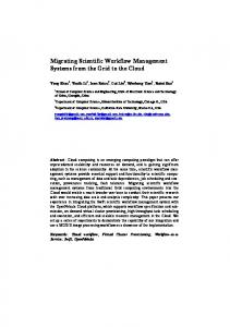
4. The analysis phase [63, 94] is to apply the output data to scientific experiments, to analyze workflow provenance data and to share the workflow information. 2.1.3 Scientific Workflow Management Systems A Workflow Management System (WfMS) is a system that defines, creates, and manages the execution of workflows. A WfMS is able to interpret the workflow process definition typically in the context of business applications. A SWfMS is a WfMS that handles and manages scientific workflow execution. It is powerful tool to execute workflows in a scientific workflow engine, which is a software service that provides the runtime environment for workflow execution [12]. In order to execute a scientific workflow in a given environment, a SWfMS typically generates a Workflow Execution Plan (WEP), which is a program that captures optimization decisions and execution directives, typically the result of compiling and optimizing a workflow, before execution. To support scientific workflow analysis, SWfMS should support additional functionality such as workflow provenance. Workflow provenance may be as (or more) important as the scientific experiment itself [53]. Provenance is the metadata that captures the derivation history of a dataset, including the original data sources, intermediate datasets, and the workflow computational steps that were applied to produce this dataset [30, 33, 62, 70]. Provenance data is used for workflow analysis and workflow reproducibility. 2.1.4 Scientific Workflow Examples Scientific workflows have been used in various scientific domains. In the astronomy domain, Montage1 is a computing and data-intensive application that can be modeled as a scientific workflow initially defined for the Pegasus SWfMS. This application is the result of a national virtual observatory project that stitches tiles of images of the sky from diverse sky surveys into a photorealistic single image [40]. Montage is able to handle a wide range of astronomical image data including the Two Micron All Sky Survey, (2MASS2 ), the Digitized Palomar Observatory Sky Survey, (DPOSS3 ), and the Sloan Digital Sky Survey (SDSS4 ) [74]. Each survey possesses huge amounts of data and covers a corresponding part of sky in visible wavelengths or nearinfrared wavelengths. 2MASS has roughly 10 terabytes, DPOSS has roughly 3 terabytes and SDSS contains roughly 7.4 terabytes. All the data can be downloaded from a corresponding server at the aforementioned links and then staged into the execution environment, such as a shared-disk file system or a database, in order to be processed. The structure of a small montage workflow is shown in Figure 1. The number within a node represents the name of an activity in the workflow. The activities (1−6) have no parent activities. Each of them exploits an mProject program to project a single image to the scale defined in a pseudo-FITS header template file. Though they invoke the same program, they have different output data dependencies and thus, they cannot be viewed as one activity. Activities (7 − 14) utilize an mDiffFit program to create a table of image-to-image difference parameters. Activity 15 takes advantage of an mFitplane program to fit the images generated by former activities (7 − 14) to an image. Activity 16 uses an mBgModel program to interactively determine a set of corrections to apply to each image to achieve a “best” global fit according to the image-to-image difference parameter table. The activities (17 − 22) remove a background from a single image through an mBackground program. Activity 23 employs an mImgtbl program to extract the 1 2 3 4
Montage project: http://montage.ipac.caltech.edu/ 2MASS: http://www.ipac.caltech.edu/2mass/ DPOSS: http://www.astro.caltech.edu/˜george/dposs/ SDSS: http://www.sdss.org/
6
Ji Liu et al.
Fig. 1: The structure of a small Montage workflow [122].
FITS header information (information about one or more scientific coordinate systems that are overlaid on the image itself) from a set of files and to create an ASCII image metadata table. Finally, Activity 24 pieces together the projected images using the uniform FITS header template and the information from the same metadata table generated by Activity 23. This activity applies an mAdd program. In the bioinformatics domain, SciEvol [100] is a workflow for molecular evolution reconstruction that aims at inferring evolutionary relationships on genomic data. To be executed in the Chiron SWfMS, SciEvol consists of 12 activities as shown in Figure 2. The first activity (preprocessing FASTA file) is a Python script to format the multi-fasta input file. FASTA file is a textual presenting format for nucleotide or peptide sequences. The second activity (MSA construction) constructs a Multiple Sequence Alignment (MSA) using a MAFFT program (or other MSA programs). A MAFFT program is generally for generating the alignment of three or more biological sequences (protein or nucleic acids) of similar length. The third activity (MSA conversion) executes ReadSeq to convert the MSA in FASTA format to that in PHYLIP format, which is used in the phylogenetic tree construction activity. The fourth activity (pre-processing PHYLIP file) formats the input file (referenced as “phylip-file-one”) according to the format definition and generates a second file (referenced as “phylip-file-two”). The fifth activity (tree construction) receives the “phylip-file-one” as input and produces a phylogenetic tree [51] as output. The sixth activities (evolutionary analysis from 6.1 to 6.6) analyze the phylogenetic tree with corresponding parameters and generate a set of files containing evolutionary information as output. Each of the activities (evolutionary phases) is related to one of six codon substitution models, which are used to verify if the groups of genes are under positive Darwinian selection. These activities exploit the same program using different parameters. The last activity (data analysis) automatically processes the output files obtained from the previous activities. There are many other data-intensive workflows in bioinformatics. For instance, SciPhylomics [106] is designed for producing phylogenomic trees based on an input set of protein sequences of genomes to infer evolutionary relationships among living organisms. SciPPGx [44] is a computing and data-intensive pharmacophylogenomic analysis workflow for providing thorough inferring
A Survey of Data-Intensive Scientific Workflow Management
7
Fig. 2: SciEvol workflow [100].
support for pharmacophylogenomic hypotheses. SciPhy [99] is used to construct phylogenetic trees from a set of drug target enzymes found in protozoan genomes. All these bioinformatics workflows have been executed using SciCumulus SWfMS [34]. The components of scientific workflows can be classified by their functionality, motifs, or structure patterns. The functionality can be data processing, activity scheduling, activity execution, and resource management [10]. The motifs may be data-oriented and workflow-oriented. Data-oriented motifs consist of recurring activities such as data storage [12], data analysis, data cleaning, data moving [12] and data visualization. Workflow-oriented motifs may correspond to remote invocations, repetitive activities, parameter sweep workflows and meta-workflows [12, 57]. A parameter sweep workflow is a workflow with multiple input parameter sets, which needs to be executed for each input parameter set [25, 64]. A meta-workflow is a workflow composed of sub-workflows. Workflow structure patterns can be patterns for parallelization, e.g. representing scientific workflows as algebraic expressions [102], or component structure patterns, e.g. single activity with one or more input/output dependencies, sequential control and sequential/concurrent data, synchronization of sequential data, data duplication [138]. Moreover, similar structure patterns of scientific workflows can be found based on a similarity model of nodes and edges in the workflow DAG [15]. Identifying scientific workflows or workflow components of the same type enables workflow information sharing and reuse (see Section 2.2.2) among workflow designers [138].
2.2 Functional Architecture of SWfMSs The functional architecture of a SWfMS can be layered as follows [41, 144, 10, 102]: presentation, user services, WEP generation, WEP execution and infrastructure. Figure 3 shows this architecture. The higher layers take advantage of the lower layers to realize more concrete functionality. A user interacts with a SWfMS through presentation and realizes the desired functions at user services layer. A scientific workflow is processed at WEP generation layer to produce a WEP,
8
Ji Liu et al.
Fig. 3: Functional architecture of a SWfMS.
which is executed at the WEP execution layer. The SWfMS accesses the physical resources through the infrastructure layer for scientific workflow execution. The combination of WEP generation layer, WEP execution layer and infrastructure layer corresponds to a scientific workflow execution engine. 2.2.1 Presentation Layer The presentation layer serves as a User Interface (UI) for the interaction between users and SWfMSs at all stages of the scientific workflow life cycle. The UI can be textual or graphical. This interface is responsible for designing a workflow by assembling data processing activities linked by dependencies. This layer also supports the functionality of showing execution status, expressing workflow steering and information sharing commands. The language for the textual interface is largely used for designing scientific workflows in SWfMSs. Different from batch scripts, the textual language supports parallel computations on distributed computing and storage resources. The configuration or administration becomes complicated in this environment while the language defined by a SWfMS should be easy to use. Most SWfMS languages support the specification of a workflow in a DAG structure while some SWfMS languages also support iteration for DCG. Wilde et al. [135] propose a distributed parallel scripting language called Swift. Swift supports workflow specifications in both DAG and DCG. It is a C-like syntax that describes data, data flows and applications by focusing on concurrent execution, composition and coordination of independent computational activities. Variables are used in Swift to name the local variables, arguments, and returns of a function. The variables in Swift have three types: primitive, mapped, and collection. Primitive variables have the basic data structures such as integer, float, string, boolean and array. Mapped variables refer to files external to the Swift script. Collection variables are in the structures that contain a set of variables, such as arrays. Swift operations have three categories: built-in functions, application interface functions and compound functions. Built-in functions are implemented by the Swift runtime system to perform various utility functions such as numeric conversion, string manipulation, etc. An application interface function provides the information to the Swift runtime system to invoke a program. A compound function is a function that invokes other functions.
A Survey of Data-Intensive Scientific Workflow Management
9
Pegasus uses Wings to create scientific workflows [59]. The workflows are created through three stages in Pegasus/Wings: the first stage specifies the abstract structure of the workflow and creates a workflow template; the second stage specifies what data to be used in the workflow and creates a workflow instance; the third stage specifies the data replicas and their locations to form an executable workflow. The later stage is done by Pegasus while the first two are realized by Wings. In Wings, workflow and its activities are represented as semantic objects. The programs are represented as workflow components to process data, which is represented as individual files or file collections. An activity is represented as a node that contains a set of computations, which may contain one computation component or a collection of computations. The data dependencies are represented as links to carry data from or to a workflow node. After the presentation of programs, activities and data dependencies, a workflow template is created. With the binding of input data sets, a workflow instance is generated as a DAG in XML format. Then, Pegasus automatically maps the workflow instance to distributed computing nodes to form an executable workflow and manages workflow execution. Chiron [102] also represents the scientific workflow activities and dependencies as a DAG in XML textual format. Ogasawara et al. [101] propose an algebraic language implemented in Chiron to encapsulate the workflow activities in six operators: Map, SplitMap, Reduce, Filter, SRQuery and JoinQuery. The Map operator consumes and produces a basic data chunk, which represents the data chunk that has a smallest amount of data while it contains all the necessary data to be processed in an activity. The SplitMap operator consumes a basic data chunk while it produces several basic data chunks. The Reduce operator reduces several basic data chunks to one basic data chunk. The Filter operator removes useless data chunks. SRQuery and MRQuery are traditional relational algebra expressions. Each activity corresponds to an operator. During workflow execution, these operators are able to parallelize the workflow execution onto the distributed computation resources. Taverna utilizes a simple conceptual unified flow language (Scufl) to represent the workflow [104]. Scufl is an XML-based language, which consists of three main entities: processors, data links, and coordination constraints. Processors represent a computational activity in a scientific workflow. Data links and coordination constraints separately represent the data dependencies and control dependencies between two activities. SWfMSs such as Galaxy [60], Taverna [104] and Kepler [10] offer a GUI for workflow design. The GUI simplifies the designing process of a scientific workflow for the SWfMS users to assemble the workflow components described as icons through drag-and-drop functionality. Graphical SWfMSs combine the efficiency of scientific workflow design and the ease of scientific workflow representation. Desktop-based graphical SWfMSs are typically installed either in a local computer or in a remote server that is accessible through network connection. The local computer or remote server can be connected to large computing and storage resources for large-scale scientific workflow execution. Some graphical SWfMSs such as Galaxy are web-portal-based, which makes it easy to share workflow information among the SWfMS users. With these SWfMSs, a scientific workflow is generally designed in a browser on the client side but executed in a private or public web server. Some of the graphical SWfMSs take textual languages as inner representation of a scientific workflow. For instance, Taverna utilizes Scufl within the SWfMS while Galaxy represents workflows in JSON format [5].
2.2.2 User Services Layer The user services layer is responsible for supporting user functionality, i.e. workflow monitoring and steering, workflow information sharing and providing workflow provenance data.
10
Ji Liu et al.
Scientific workflow monitoring makes it possible to get real-time execution status for SWfMS users. Since scientific workflow execution may take a long time, dynamic monitoring and steering of the execution are important to control workflow execution [38]. Workflow monitoring tracks the execution status and displays this information to users during workflow execution [27]. Through workflow monitoring, a scientist can verify if the result is already enough to prove her hypothesis [30]. Workflow monitoring remains an open challenge as it is hard to fully support. However, it can be achieved based on log data (in log files) or more general provenance data, typically in a database [93]. Gunter et al. [66] and Samak et al. [118] propose the Stampede monitoring infrastructure for real-time workflow monitoring and troubleshooting. This infrastructure takes a common data model to represent scientific workflow execution and utilizes a high-performance loader to normalize the log data. It offers a query interface for extracting data from the normalized data. It has been initially integrated with Pegasus SWfMS and then adapted in Triana SWfMS [130]. Horta et al. [70] propose a provenance interface to describe the production and consumption relationships between data artifacts such as output data files and computational activities at runtime for workflow monitoring. This interface can be used to select the desired output data to monitor the workflow execution for SWfMS users through browsers or a high-resolution tiled display. This interface is based on on-line provenance query supported by algebraic approach. The on-line provenance query is different from the provenance collected at runtime, but made available only after the execution, where monitoring is no longer possible. This interface is available for Chiron [102] or SciCumulus [34] that store all the provenance data in a relational database. SciCumulus is an extension of Chiron for cloud environments. Workflow steering is the interaction between a SWfMS and a user to control the workflow execution progress or configuration parameters [93]. Thus, through workflow steering, a scientist can control workflow execution dynamically so that she does not need to continue unnecessary execution or execute a scientific workflow again when an error occurs [30, 62]. Scientific workflow steering, which still remains an open issue, saves much time for SWfMS users. Information sharing functionality enables workflow information sharing for workflow reusing. Through workflow information sharing, SWfMS users of the same SWfMS environments or different SWfMS environments can share workflow information including workflow design, the input data or the output data. Since designing a scientific workflow is challenging work, workflow information sharing is useful to reduce repetitive work between different scientist groups. A SWfMS can directly integrate workflow repositories to support workflow information sharing. A workflow repository is a workflow information pool, where workflow data (input data and output data), workflow designs (structures) and available programs (to be used in activities of workflows) are stored. The workflow repository can contain shared workflows for the same SWfMS environments, e.g. “ the myExperiment” social network [136] for Taverna, the web-based sharing functionality of Galaxy [60], the workflow hosting environment for Askalon [68], or for different SWfMS environments, e.g. SHIWA Repository [126]. The workflow repositories should support workflow uploading, publishing, download or searching. The workflows for different SWfMS environments can be adapted to an intermediate representation [113] to compose a meta-workflow, which can be executed by execution platforms such as SHIWA [127], with corresponding SWfMS engines for the sub-workflows. Except for SHIWA, the information sharing indicates workflow information sharing among the users of the same SWfMS environment. Provenance data in scientific workflows is important to support reproducibility, result interpretation and problem diagnosis. Provenance data management concerns the efficiency and effectiveness of collecting, storing, representing and querying provenance data. Different methods have been proposed for different SWfMSs. Gadelha et al. [55] develop MTCProv, a provenance component for the Swift SWfMS. Swift optionally produces provenance information in its log files while this data is exported to relational databases by MTCProv. MTCProv supports a data
A Survey of Data-Intensive Scientific Workflow Management
11
model for representing provenance and provides a provenance query interface for the visualization of provenance graphs and querying of provenance information. Kim et al. [81] present a semanticbased approach to generate provenance information in the Wings/Pegasus framework. Wings is a middleware that supports the creation of workflow templates and instances, which are then submitted to Pegasus. This approach produces activity-level provenance through the semantic representations used in Wings, and execution provenance through Pegasus’ task scheduling and execution process. SPARQL (SPARQL Protocol and RDF Query Language), a semantic query language, is used for querying provenance data. Costa et al. [30] propose PROV-Wf, a practical approach for capturing and querying provenance data for workflows. PROV-Wf gathers provenance data in different granularities based on PROV recommendation [14]. The PROV-Wf contains three main parts: the structure of the experiment, execution of the experiment and environment configuration. PROV-Wf supports prospective and retrospective provenance data allowing for on-line provenance queries through SQL. The provenance database of this approach acts as a statistics catalog from DBMS. Altintas et al. [8] present a provenance information collection framework for Kepler. This framework can collect provenance information thanks to its implementation of event listener interfaces. Moreover, Crawl et al. [31] introduce a provenance system that manages provenance data from Kepler. This system records both data and dependencies of tasks executing on the same computing node. The provenance data is stored in a MySQL database. The Kepler Query API is used to retrieve provenance information and to display provenance graphs of workflow execution. 2.2.3 WEP Generation Layer The WEP generation layer is responsible for generating a WEP according to a scientific workflow design as shown in Figure 4. This layer contains three processes, i.e. workflow refactoring, workflow parallelization and optimization. The workflow refactoring module refines the workflow structure for WEP generation. For instance, Ogasawara et al. [101, 102] take advantage of a workflow algebra to generate equivalent expressions, which are transformed into WEPs to be optimized. When a scientific workflow representation is given, it is generally not adapted for an execution environment or a SWfMS. Through workflow refactoring, a SWfMS can transform the workflow into a simpler one, e.g. by removing redundant or useless activities, and partition it into several pieces, called fragments (by analogy with program fragments), to be executed separately by different nodes or sites. A SWfMS can schedule fragments to reduce scheduling complexity [22]. Thus, workflow partitioning is the process of decomposing a workflow into (connected) workflow fragments to yield distributed [89] or parallel processing. A workflow fragment (or fragment for short) can be defined as a subset of activities and data dependencies of the original workflow (see [101] for a formal definition). Note that the term workflow fragment is different from the term sub-workflow, although they are sometimes confused. However, the term sub-workflow is used to refer to the relative position of a workflow in a workflow composition hierarchy [129]. Workflow partitioning is addressed in [22] for multiple execution sites (computer clusters explained in Section 2.2.5) with storage constraints. A method is proposed to partition a big workflow into small fragments, which can be executed in an execution site with moderate storage resources. In addition, Deelman et al. [41] propose an approach to remove workflow activities for workflow refactoring. This approach reduces redundant computational activities based on the availability of the intermediate data produced by previous execution. Tanaka and Tatebe [124] use a Multi-Constraint Graph Partitioning (MCGP) algorithm [80] to partition a workflow into fragments, which has equal weight value in each dimension while the weight of the edges crossing between fragments is minimized. In this method, each activity is defined as a vector of multiple values and each dependency be-
12
Ji Liu et al.
Fig. 4: WEP generation.
tween different activities has a value. This method balances the activities in each fragment while minimizing associated edges between different fragments. Moreover, workflow refactoring can also reduce workflow structure complexity. Cohen-Boulakia et al. [28] present a method to automatically detect over-complicated structures and replace them with easier equivalent structures to reduce workflow structure complexity. Workflow parallelization exploits different types of parallelism to generate concrete executable tasks for the WEP. The parallelization can be performed at sub-workflow level and activity, task level. The parallelization at sub-workflow level is realized by executing different sub-workflows in corresponding scientific workflow execution engines in parallel. The parallelization at activity or task level encapsulates the related data, i.e. input, instruction and parameter data, into a task; Then, an activity may correspond to several tasks that can be executed in parallel. Swift [144], Pegasus [41], Chiron [102] and some other SWfMSs can achieve workflow parallelization using Message Passing Interface (MPI) [123] (or an MPI-like language) or a middleware within their execution engine. Since they have full control over the parallel workflow execution, these SWfMSs can leverage parallelism at different levels and yield the maximum level of performance. Some other SWfMSs outsource parallelization and workflow scheduling (see Section 2.2.4) to external execution tools, e.g. web services or Hadoop MapReduce systems. These SWfMSs can achieve activity parallelism but data parallelism (see Section 3.1.1) is generally realized in the external execution tools. The SWfMSs that outsource parallelization to a Hadoop MapReduce system adapt a data analysis process to a MapReduce workflow, composed of Map and Reduce activities. These SWfMSs generate corresponding MapReduce tasks and submit the tasks to the MapReduce system. Wang et al. [132] propose an architecture that combines the Kepler workflow engine with the Hadoop MapReduce framework to support the execution of MapReduce workflows. Delegating parallelization and parallel execution to an external engine makes it easy for the SWfMS to deal with very large data-intensive tasks. However, this approach is not as efficient as direct support of parallelism in the SWfMS. In particular, it makes the SWfMS loose control over the entire workflow execution, so that important optimizations, e.g. careful placement of intermediate data exchanged between tasks, cannot be realized. Furthermore, provenance management becomes almost impossible as the external tools typically do not support provenance. Workflow optimization captures the results of workflow refactoring and workflow parallelization and inserts additional instructions for workflow scheduling to generate a WEP. The additional instructions describe multiple objectives for workflow execution, such as minimizing execution time, meeting security restrictions and reducing resource cost. The multiple objectives are mainly attained by adjusting workflow scheduling at the WEP execution layer. Having an algebra and dataflow-oriented execution engine opens up interesting opportunities for optimization [45, 25]. For example, it allows for user interference on the execution plan, even during the execution. 2.2.4 WEP Execution Layer The WEP execution is managed at the WEP execution layer. This layer handles workflow scheduling, task execution and fault-tolerance.
A Survey of Data-Intensive Scientific Workflow Management
13
Through workflow scheduling, a SWfMS produces a Scheduling Plan (SP), which aims at making good use of computing resources and preventing execution stalling [17]. A SWfMS can schedule workflow fragments, bags of tasks or individual tasks into an execution site (computer clusters explained in Section 2.2.5) or a computing node according to different task scheduling methods. The scheduling methods are presented in Section 3.2. Some SWfMSs outsource workflow scheduling to external tools (see Section 2.2.3). Even though these SWfMSs can achieve parallelism at the task level, they cannot optimize SPs in external tools, which are generally not data-flow aware, according to the entire structure of the workflow [45]. During task execution, the input data is transferred to the computing nodes and the output data is produced. Generally, the provenance data is also generated at this time. SWfMSs can execute tasks either directly in their execution engine (e.g. Kepler, Galaxy, Pegasus, Chiron) or using an external tool (e.g. web service, MapReduce system). To enable parallel task execution, SWfMSs may exploit MPI (or an MPI-like language), SSH commands, web services, Hadoop or other middlewares. MPI and SSH allow the SWfMS to have full control of task execution. However, MPI requires using a shared file system while SSH does not. Using web services, Hadoop or other middlewares, parallel task execution moves outside the direct control of SWfMS. The workflow fault tolerance mechanism deals with failures or errors of task execution and guarantees the availability and reliability of workflow execution. According to Ganga and Karthik [56], fault-tolerance techniques can be classified into proactive and reactive. Proactive fault tolerance avoids faults and errors by predicting the failure and proactively replacing the suspected components from other working components. Reactive fault-tolerance reduces the effect of failures after perceiving failures, using check pointing/restart, replication and task resubmission techniques. Ganga and Karthik [56] propose a task replication technique based on the idea that a replication of size r can tolerate r-1 failed tasks while keeping the impact on the execution time minimal. Costa et al. [29] introduce heuristics based on real-time provenance data for detecting task execution failure and re-executing failed tasks. This heuristic re-executes failed tasks during workflow execution using extra computing resources in the cloud to reduce bad influences on the workflow execution from the task failures. 2.2.5 Infrastructure Layer The limitations of computing and storage resources of one computer force SWfMS users to use multiple computers in a cluster, grid or cloud infrastructure for workflow execution. This layer provides the interface between the SWfMS and the infrastructure. Cluster computing provides a paradigm of parallel computing for high performance and availability. A computer cluster, or cluster for short, consists of a set of interconnected computing nodes [26]. A cluster is typically composed of homogeneous physical computers interconnected by a high speed network, e.g. Fast Ethernet or Infiniband. A cluster can consist of computer nodes in the grid or supercomputers [32]. In addition, the cluster can also consist of virtual machines in the cloud. In the cloud, a virtual machine (VM ) is a virtualized machine (computer), i.e. a software implementation of a computer that executes programs (like a real computer) while abstracting away the details of physical hardware [143]. Cluster users can rely on message passing protocols, such as MPI for parallel execution. According to Foster and Kesselman [52], a grid is a hardware and software infrastructure that manages distributed computers to provide good quality of service through standard protocols and interfaces with a decentralized control mechanism. A grid federates geographical distributed sites that are composed of diverse clusters belonging to different organizations through complex coordinating mechanisms to serve as a global system. Furthermore, it has rules to define who can use what resources for what destination [52]. In addition, a particular grid, i.e. desktop grid,
14
Ji Liu et al.
exists for scientific workflow execution [117]. Compared to cluster computing, grid computing gathers heterogeneous computer resources to provide more flexible services to diverse users by inner resource allocation mechanisms. Cloud computing provides computing, storage and network resources through infrastructure, platform and software services, with the illusion that resources are unlimited. Although sometimes confused, there are five main differences between cloud computing and grid computing. The first one is that the cloud uses virtualization techniques to provide scalable services that are independent of the physical infrastructure. The second one is that it not only provides infrastructure services such as computing resources or storage resources but also platform and software services. In the cloud, we can configure and use a cluster composed of VMs. Moreover, database management systems can be offered as platform in the cloud. The third difference is the possibility of dynamic provisioning. In a grid environment, a list of resources is generally fixed during the entire execution of the workflow. Thus, it is very unusual to use dynamic provisioning in the grid as it does not provide any benefit. In contrast, in cloud environments, we have a list of resource types from which we can provision a potentially unlimited number of resource instances. Such dynamic provisioning can provide much more benefits, in particular better performance, and reduced financial cost. The fourth difference is in the use of service-level agreement (SLA), which defines the quality of service provided to users by service providers [134]. Cloud SLA includes relatively full performance metrics for on-demand services [18] while grid SLA is relatively informal. The fifth difference is that the cloud provides support for pricing and accounting services, which is not necessary in the grid. Some grids evolve towards the cloud. For instance, Grid’5000[2] is a grid in France which provides virtualized resources and services for big data (e.g. Hadoop). The operational layer is also in charge of provisioning, which can be static or dynamic. Static provisioning can provide unchangeable resources for SWfMSs during workflow execution while dynamic provisioning can add or remove resources for SWfMSs at runtime. Based on the types of resources, provisioning can be classified into computing provisioning and storage provisioning. Computing provisioning means offering computing nodes to SWfMSs while storage provisioning means providing storage resources for data caching or data persistence. However, most SWfMSs are just adapted to static computing and storage provisioning. The data storage module generally exploit database management systems and file systems to manage all the data during workflow execution. Some SWfMSs such as Taverna put intermediate data and output data in a database. As proposed in [145], some SWfMSs such as Pegasus and Chiron utilize a shared-disk file system, i.e. a system that stores the data in additional (relative to the computing nodes) separated storage resources. Some SWfMSs such as Kepler [132] can exploit distributed file systems, i.e. a system stores data directly in the file system constructed by gathering storage space in each computing node in a shared-nothing architecture. Some SWfMSs such as Pegasus can directly take advantage of the local file systems in each computing node. Generally, the file systems and the database management systems take advantage of computing nodes and storage resources provided by the provisioning module. In a multisite environment, SWfMSs can cluster the data and place each data set at a single site, distribute the newly generated data to multiple sites at runtime and adjust data among multiple sites [141]. SWfMSs can also put some data in the disk cache of one computing node to accelerate data access during workflow execution [121]. However, existing SWfMSs just use few types of storage resources, some other types of storage resources, e.g. cache for a single site, cache in one computing node etc., can be also exploited.
A Survey of Data-Intensive Scientific Workflow Management
15
2.3 Techniques for Data-intensive Scientific Workflows Because they deal with big data, data-intensive scientific workflows have some features that make them more complicated to handle, compared with traditional scientific workflows. From the existing solutions, we can observe three main features, which we briefly discuss. The first feature is the diversity of data sources and data formats in data-intensive scientific workflows. The data can consist of the input data stored in a shared-disk file system and the intermediate data stored in a database. The data of various data sources differ in data transfer rate, data processing efficiency and data transfer time. These differences have a strong influence on workflow design and execution. However, the workflow representation method composed of activities and dependencies for general workflows can only depict different computational components and the data dependencies among them. Thus, the data-intensive workflow representation should be adapted to be able to depict the diverse types of data. The second feature is that moving some program code (i.e. instruction data) to where the input data is can be more efficient than moving the data to the code. This is true when the input data sets are very big while the corresponding instruction data is small. The decision of moving code to where the data is should be done during the deployment phase in the workflow life cycle (see Section 2.1.2), in order to optimize workflow execution according to the characteristics of the input data. However, moving program codes across computing nodes is not always possible, for instance, because of proprietary rights or runtime compatibility. The third feature is that not all the data needs to be kept all along the workflow execution [42]. In particular, given fixed constraints on storage capacity allocated to the workflow execution, the intermediate data may be too big to be kept. Thus, it is important to discover and keep only the necessary data, to remove redundant data and to compress the data that is not used frequently. There have been several studies that propose techniques for data-intensive workflow representation, data processing and redundant data removing, which we discuss below. Albrecht et al. [7] propose a makeflow method for representing and running a data-intensive workflow. In their system, the input data of each activity should be explicitly specified for workflow representation or the workflow description will be regarded as incorrect. An example is shown in Figure 5 with a BLAST workflow (from bioinformatics) that has four types of activities. The first activity takes input data and splits the data into several files. The second type of (BLAST) activities searches for similarities between a short query sequence and a set of DNA or amino acid sequences [85]. The third type of activities (cat) regroups the output and errors of BLAST activities into two files. The last activity (finish) generates the final results. In Figure 5, the input data and the intermediate data are represented explicitly for further workflow textual description and execution. Deng et al. [43] propose a task duplication approach in SWfMS for scheduling tasks onto multiple data centers. They schedule the tasks by comparing the task computational time and output data transmission time. For instance, let us consider two data centers as depicted in Figure 6. Tasks t 1 and t 3 and the corresponding input data d 1, d 3 are located at data center dc 1. Task t 2 at data center dc 2 needs to take the output of task t 3 as input data d 2. We note as T 1 the time to transfer the data d 2 from data center dc 1 to data center dc 2. We note as T 2, the sum of the time to transfer the input data d 3 from data center dc 1 to data center dc 2 and the time to execute task t 3. If time T 1 is longer than time T 2, the SWfMS will duplicate task t 3 from data center dc 1 to data center dc 2 to reduce execution time as shown in Figure 6 (b). If not, the SWfMS executes the tasks as they are and transfers the output of task t 3 to data center dc2 as shown in Figure 6 (a). Furthermore, Raicu et al. [115] propose a data-aware scheduling method for data-intensive application scheduling. This approach schedules the tasks according to data location and available execution computing resources.
16
Ji Liu et al.
Fig. 5: BLAST workflow [7].
Fig. 6: Task duplication [43].
Yuan et al. [141] build an Intermediate data Dependency Graph (IDG) from data provenance of workflow execution. Based on IDG, a novel intermediate data storage strategy is developed to store the most appropriate intermediate datasets instead of all the intermediate data to reduce the storage cost during execution. Ramakrishnan et al. [116] propose an approach for scheduling data-intensive workflows onto storage-constrained distributed resources. This approach minimizes
A Survey of Data-Intensive Scientific Workflow Management
17
the amount of data by removing needless data and scheduling workflow tasks according to the storage capacity on individual resources. There are some other techniques for data-intensive workflows, in particular, algebraic optimization and data transfer optimization. Dias et al. [45] discuss several performance advantages of having an algebra and dataflow-oriented execution engine for data-intensive applications. They argue that current main approach that statically generates a WEP or an execution plan for Hadoop leaves no room for dynamic runtime changes. They propose that dataflow-based dataintensive workflows can be executed by algebraic SWfMS, such as Chiron and Scicumulus, with efficient algebraic optimizations. Moreover, we can take advantage of the former data transfer orders or current data location to control data transfer for reducing the makespan of data-intensive workflow execution. Chervenak et al. [24] describe a policy service that provides advice on data transfer orders and parameters based on ongoing and recent data transfers and current allocation of resources for data staging. 3 Parallel Execution in SWfMSs Since data-intensive scientific workflows handle large input or intermediate datasets in large scale experiments, SWfMSs rely on the parallel techniques on multiple computers to accelerate the execution. Workflow parallelization is the process of transforming and optimizing a (sequential) workflow into a parallel WEP. WEP allows the SWfMS to execute the workflow in parallel in a number of computing nodes, e.g. in a cluster. It is similar to the concept of Query Execution Plan (QEP) in distributed database systems [110]. This section introduces the basic techniques for the parallel execution of workflows in SWfMSs: workflow parallelization techniques; scientific workflow scheduling algorithms; and parallelization in the cloud. The section ends with concluding remarks. 3.1 Workflow Parallelism Workflow parallelization identifies the tasks that can be executed in parallel in the WEP. Similar to parallel query processing [110], whereby a QEP can be parallelized based on data and operator dependencies. There are two parallelism levels: coarse-grained parallelism and fine-grained parallelism. Coarse-grained parallelism can achieve parallelism by executing sub-workflows in parallel. Fine-grained parallelism realizes parallelism by executing different activities in parallel. If a workflow is composed of sub-workflows, it can be executed in parallel at coarse-grained level to parallelize the execution of sub-workflows and then, executed in parallel at fine-grained level to parallelize the execution of activities within sub-workflows. If a workflow is directly composed of activities, it can just be executed at fine-grained parallelism level to parallelize the execution of activities. According to the dependencies defined in a scientific workflow, different parallelization techniques can result in various execution plans. Some parameters can be used to evaluate the efficiency of each technique. An important parameter of parallelization is the degree of parallelism, which is defined as the number of concurrently running computing nodes or threads at any given time and that can vary for a given workflow depending on the type of parallelism [19]. 3.1.1 Coarse-Grained Parallelism Coarse-grained parallelism is performed at workflow level, which is critical to the execution of meta-workflows or parameter sweep workflows. To execute a meta-workflow, the independent
18
Ji Liu et al.
sub-workflows are identified as workflow fragments to be submitted to corresponding execution workflow execution engine [126]. The execution of a parameter sweep workflow corresponds to the execution of the workflow with different sets of input parameter values. The combination of workflow and each set of input parameter values is viewed as independent sub-workflows, which can be run in parallel [77]. The coarse-grained parallelism for parallel execution of sub-workflows resembles to the independent activity parallelism presented in the next section.
3.1.2 Fine-Grained Parallelism The fine-grained parallelism is realized within a workflow or a sub-workflow (for meta-workflows). Three types of parallelism exist at this level: data parallelism, independent parallelism and pipeline parallelism. Data parallelism deals with the parallelism within an activity while independent parallelism and pipeline parallelism handle the parallelism between different activities.
Data Parallelism Data parallelism, similar to intra-operator parallelism in [110], is obtained by having multiple tasks performing the same activity, each on a different data chunk. As shown in Figure 7(b), data parallelism happens when the input data of an activity can be partitioned into different chunks and each chunk is processed independently by a task in a different computing node or processor. As the input data needs be partitioned, e.g. by a partitioning task, the activity result is also partitioned. Thus, the partitioned output data can be the base for data parallelism for the next activities. However, to combine the different results to produce a single result, e.g. the final result to be delivered to the user, requires special processing, e.g. by having all the tasks writing to a shared disk or sending their results to a task that produces the single result. Data parallelism can be static, dynamic or adaptive [112]. If the number of data chunks is indicated before execution and fixed during execution, the data parallelism is static. If the number of data chunks is determined at run-time, the data parallelism is dynamic. In addition, if the number is automatically adapted to the execution environment, the data parallelism is adaptive. The adaptive data parallelism can determine the best number of data chunks to balance the workflow execution, to increase parallelism degree while maintaining a reasonable overhead.
Independent Parallelism Different activities of a workflow can be executed in parallel over several computing nodes. Two activities can be either independent, i.e. the execution of any activity does not depend on the output data of the other one, or dependent, i.e. there is a data dependency between them. Independent parallelism exploits independent activities while pipeline parallelism (see next subsection) deals with dependent activities. Independent parallelism is achieved by having tasks of different independent activities executed simultaneously. As shown in Figure 7(c), independent parallelism occurs when a scientific workflow has more than one independent part in the workflow graph and the activities in each part have no data dependencies with those in another part. To achieve independent parallelism, a SWfMS should identify activities that can be executed in parallel. SWfMSs can partition the workflow into independent parts (or workflow fragments) of activities to achieve independent parallelism.
A Survey of Data-Intensive Scientific Workflow Management
19
(a) Sequential execution in one computing node. Activity B starts execution after the execution of activity A and activity C starts execution after the execution of activity B. All the execution is realized in one computing node.
(b) Data parallelism. The execution of activities A, B, C is performed in two computing nodes simultaneously. Each computing node processes a data chunk.
(c) Independent parallelism. The execution of activities A and B is performed in two computing nodes simultaneously. Activity C begins execution after the execution of activities A and B.
(d) Pipeline parallelism. Activity C starts execution once a data chunk is ready. When activities A and B are processing the second part of data (i2, i4), activity C can process the output data of the first part (a1, b1) at the same time.
(e) Hybrid parallelism. Activity A is executed through data parallelism at nodes 1 and 2. Activity B is executed through data parallelism at nodes 4 and 5. Activities A and B are also executed through independent parallelism. Activities A and C, respectively B and C, are executed through pipeline parallelism between nodes (1, 2) and 3, respectively nodes (4, 5) and 3.
Fig. 7: Different types of parallelism. Circles represent activities. There are three activities: A, B and C. C processes the output data produced by A and B. Rectangles represent data chunks. “i1” stands for the first part of input data. “a1” stands for the output data corresponding to the first part of input data after being processed by activity A.
20
Ji Liu et al.
Pipeline Parallelism With pipeline parallelism (see Figure 7(d)), several dependent activities with a producer-consumer relationship are executed in parallel by different tasks. One output data chunk of one activity is consumed directly by the next dependent activities in a pipeline fashion. The advantage of pipeline execution is that the result of the producer activity does not need to be entirely materialized. Instead, data chunks can be consumed as soon as they are ready, thus saving memory and disk accesses. Hybrid Parallelism As shown in Figure 7(e), the three basic types of parallelism can be combined to achieve higher degrees of parallelism. A SWfMS can first perform data parallelism within each activity. Then, it can partition the workflow into independent parts or workflow fragments for independent activities, e.g. with each part or fragment for execution in a different computing node. Finally, pipeline parallelism can be applied for executing dependent activities in parallel. In addition, the parallelism strategies may also be changed at runtime, according to the parallel computing environment behavior [33]. For the activities that process output data produced by more than one activity, the data is generally merged for the follow-up activity. This merging operation can also be found in the shuffle phase of the MapReduce program execution. By combining these mechanisms, the degree of parallelism can be maximized at different execution layers. We illustrate different types of parallelism, including their combination in hybrid parallelism, with the example shown in Figure 7. In this figure, one task consists of one activity and the related input data. Figure 7(a) presents the sequential execution of Activity A, B, C and two parts of input data, i.e. i1 and i2 . Since there is no parallelization, the corresponding tasks, i.e. Activity A and Data i1 , Activity A and Data i2 , Activity B and Data i3 , Activity B and Data i4 , Activity C and Data a1 , b1 , Activity C and Data a2 , b2 , are executed one after another. Figure 7(b) describes the execution with data parallelism. The processing of each part of input data is done in different computing nodes in parallel, i.e. the processing of input data i1 , i3 and that of input data i2 , i4 are done at the same time. Figure 7(c) shows independent parallelism. Activity A and B are executed at different computing nodes at the same time. Figure 7(d) shows pipeline parallelism, i.e. the parallel execution of Activity A (or B) and Activity C. Activity A (or B) can be done at the same time as Activity C while processing the different parts of input data. While Activity C is processing Data a1 and b1 at Node 2, which corresponds to the input data i1 and i3 , Activity A (or B) can process the input data i2 (or i4 ). Figure 7(e) shows hybrid parallelism. Thus, the tasks, i.e. Activity A and Data i1 , Activity A and Data i2 , Activity B and Data i3 , Activity B and Data i4 can be executed in parallel in different computing nodes. Activity C can begin execution once both Data a1 and b1 (or both Data a2 and b2 ) are ready. This parallelism combines data parallelism, independent parallelism and pipeline parallelism. 3.2 Workflow Scheduling Workflow scheduling is a process of allocating concrete tasks to computing resources (i.e. computing nodes) to be executed during workflow execution [19]. The goal is to get an efficient Scheduling Plan (SP) that minimizes a function based on resource utilization, workflow execution cost and makespan. Since a SWfMS can schedule bags of tasks, there may be a task clustering phase to generate task bags. Moreover, scheduling methods can be static, dynamic or hybrid. The SWfMSs that schedule workflow tasks without external tools choose computing nodes to execute tasks without constraints. The SWfMSs that outsource workflow parallelization or
A Survey of Data-Intensive Scientific Workflow Management
21
workflow scheduling may relay on external tools to schedule tasks. The following scheduling methods focus on the SWfMSs that manage workflow scheduling by themselves. 3.2.1 Task Clustering A SWfMS can schedule bags of tasks to a computing nodes or multiple computing nodes to reduce the scheduling overhead so that the execution time can be reduced. A bag of tasks contains several tasks to be executed in the same computer. Note that bags of tasks are different from workflow fragments. Workflow fragments are generated by analyzing activities while bags of tasks are produced by grouping executable tasks. Several studies have been done for generating bags of tasks. Deng et al. [43] present a clustering method for efficient scientific workflow execution. They use a k-means clustering method to group the tasks into several task bags according to different dependencies: data-data dependency, task-task dependency, and task-data dependency. These three types of dependencies are used to measure the correlations between datasets and tasks in a workflow. W. Chen et al. [23] present a balanced task clustering approach for scientific workflow execution. They cluster the tasks by balancing total execution of each bag of task. 3.2.2 Static Scheduling Static scheduling generates a SP that allocates all the executable tasks to computing nodes before execution and the SWfMS strictly abides the SP during the whole scientific workflow execution [19]. Because it is before execution, static scheduling yields little overhead at runtime. It is efficient if the SWfMS can predict the execution load of each task accurately, when the execution environment varies little during the workflow execution, and when the SWfMS has enough information about the computing and storage capabilities of the corresponding computers. However, when the execution environment experiences dynamical changes, it is very difficult to achieve load balance. The static task scheduling algorithms have two kinds of processor selection methods [128]: heuristic-based and guided random search based. The heuristic-based method schedules tasks according to a predefined rule while the random search based method schedules tasks randomly. Static task scheduling algorithms can also be classified between task-based and workflow-based [16]. The task-based method directly schedules tasks into computing nodes while the workflowbased method schedules a workflow fragment into computing nodes. Since the workflow-based method transfers the data with less overhead compared to the task-based method, it is better for data-intensive applications. Topcuouglu et al. [128] propose two static scheduling algorithms: Heterogeneous EarliestFinish-Time (HEFT) and Critical-Path-on-a-Processor (CPOP). Both algorithms contain a task prioritizing phase and a processor selection phase. The task prioritizing phase is for ranking tasks while the processor selection phase is for scheduling a selected task on a “best” computing node, which minimizes the total execution time. We note the average computation cost of a task as CPC and the average communication cost of the current task to another task as CMC. The rank u is the rank that is based on CPC and CMC that represents the communication from the current task to a succeed task. The rank d indicates the rank based on CPC and CMC consisting of the communication from a preceding task to the current task. In the task prioritizing phase, HEFT ranks tasks based on rank u. In the processor selection phase, HEFT selects a computing node, which finishes its current task firsts. HEFT can also insert a task in a computing node when there is idle time between the execution of two consecutive tasks. The CPOP algorithm uses a rank c that combines both rank u and rank d in the task prioritizing phase. It utilizes a critical path in the processor selection phase. A critical path is a pipeline of tasks, in which a task has no more than one input dependency and no more than one output dependency. Each task in the
22
Ji Liu et al.
critical path has the highest priority value (in rank c) in all the tasks that have the input data dependencies from the same parent task. CPOP chooses a computing node as a critical-path processor and schedules the tasks in the critical path to the critical-path processor. It schedules the other tasks to the other computing nodes with the same mechanism as HEFT. 3.2.3 Dynamic Scheduling Dynamic scheduling produces SPs that distribute and allocate executable tasks to computing nodes during workflow execution [19]. This kind of scheduling is appropriate for scientific workflows, in which the workload of tasks is difficult to estimate, or for environments where the capabilities of the computers varies a lot during execution. Dynamic scheduling can achieve load balancing while it takes time to dynamically generate SPs during execution. The scheduling algorithms can be based on the queue techniques in a publish/subscribe model with different strategies such as First In First Out (FIFO), adaptive and so on. SWfMSs such as Swift [135], Chiron [102], and Galaxy [79] exploit dynamic scheduling algorithms. Dynamic SPs may be generated by adapting a static scheduling method to dynamic environment. Yu and Shi [140] introduce an HEFT-based dynamic scheduling algorithm. This algorithm is suited to the situation where a scientific workflow has been executed partially before scheduling. It schedules the tasks by applying an HEFT-based algorithm according to a dynamically generated rank of tasks. There are some original approaches to generate dynamic SPs. Maheswaran et al. [91] present a min-min algorithm that is designed as a batch mode scheduling of two steps. First, a list of tasks ready to be executed is created. This phase is called “task prioritizing” phase. Then, the tasks in the list are scheduled to computing nodes based on a heuristic. The heuristic maps the task T to the computing node M such that T is the task that has minimum expected execution time in the non-mapped tasks and that M is the computing node that is executing a task having minimum expected execution time in the mapped tasks. This phase is called the “resource selection” phase. Anglano and Canonico [11] present several knowledge-free scheduling algorithms that are able to schedule multiple bags of tasks. A knowledge-free algorithm does not require any information on the resources for scheduling. These algorithms implement different policies: First Come First Served – Exclusive (FCFS-Excl), First Come First Served – Shared (FCFS-Share), Round Robin (RR), Round Robin –No Replica First (RR-NRF) and Longest Idle. With the FCFS-Excl policy, bags of tasks are scheduled in order of arrival. Different from FCFS-Excl, FCFS-Share can allocate more than one bag of tasks to a computing node. The RR policy schedules bags of tasks in a fixed circular order while all the bags have the same probability to be scheduled. With the RR-NRF policy, a bag of tasks that does not have any task executed will be given priority. In this policy, all the bags of tasks have at least a task running. The longest idle policy tries to reduce waiting time by giving preference to the bag of tasks hosting the task that exhibits the largest waiting time. The paper shows that the FCFS-based policy performs better for small task granularity scheduling. 3.2.4 Hybrid Scheduling Both of static and dynamic scheduling have their own advantages and they can be combined as a hybrid scheduling method to achieve better performance than just using one or the other. For example, a SWfMS might schedule a part of the tasks of a workflow, e.g. those tasks for which there is enough information, using static scheduling and schedule the other part during execution with dynamic scheduling [43].
A Survey of Data-Intensive Scientific Workflow Management
23
Oliveira et al. [33] propose a hybrid scheduling method with several algorithms: greedy scheduling, task grouping, task performing, and load balancing. The greedy scheduling algorithm produces static WEPs to choose the most suitable task to execute for a given idle VM based on a proposed cost model. The task grouping algorithm produces new tasks by encapsulating two or more tasks into a new one. The task performing algorithm sets up the granularity factor for each VM in the system and modifies the granularity according to the average execution time. The load balancing algorithm is a dynamic scheduling algorithm that adjusts the number of VMs and static WEP in order to meet the deadline of execution time and the budget limit. 3.2.5 Scheduling Optimization Algorithms Since there are many criteria to measure the scientific workflow execution, SWfMS users may have multiple objectives for workflow execution, such as reducing execution time, minimizing execution cost etc. Therefore, SPs should also be optimized to attain multiple objective in a given context (cluster, grid, cloud). Unlike query optimization in database, however, this optimization phase is often not explicit and mixed with the scheduling method. Though there are some existing scheduling optimization algorithms [33, 65, 49, 46], they do not consider a multisite environment with distributed data at each site. We present [65] and [49] as examples. Gu et al. [65] address the scheduling optimization problem of mapping distributed scientific workflows to maximize the throughput in unstable networks where nodes and links are subject to probabilistic failures. And they propose a mapping algorithm to maximize both throughput and reliability for workflow scheduling. They consider a network where the failure occurrences follow a Poisson distribution with a constant parameter. The mapping algorithm includes three algorithms: disLDP-F, Greedy disLDP-F and decentralized Greedy disLDP-F. The disLDP-F algorithm schedules the tasks by identifying and minimizing the global bottleneck time based on the rank of computational requirements of tasks. Greedy disLDP-F reduces the search complexity of disLDP-F by selecting the best node for each type of requirement of the current task and then generates a best computing node for the current task. The decentralized Greedy disLDP-F algorithm decentralizes the disLDP-F algorithm by storing all the parameters of each individual node locally and selecting the node through the communication between individual nodes instead of centralized control. Fard et al. [49] propose a multi-objective scheduling method of SWf execution in distributed computing infrastructures. Their approach generates a best scheduling strategy, which is a Pareto optimality (no other strategy can achieve a result of a better component while ensuring the other components of the result as well as this strategy), to achieve 4 objectives, i.e. execution time, financial cost, energy consumption and reliability. Nevertheless, this approach does not consider data distribution in a multisite environment.
3.3 Scientific Workflow Parallelization in the Cloud Cloud services can be divided into three broad categories: Software-as-a-Service (SaaS), Platformas-a-Service (PaaS) and Infrastructure-as-a-Service (IaaS). SaaS is the delivery of application software as a service. PaaS is the delivery of a computing platform with development tools and APIs as a service. IaaS is the delivery of a computing infrastructure (i.e., computing, networking and storage resources) as a service. All of the SaaS, PaaS and IaaS can be useful to develop, share and execute scientific workflows components as cloud services. However, in the rest of this paper, we focus on IaaS, which allows running existing scientific workflows in the cloud.
24
Ji Liu et al.
3.3.1 Parallelization in Single Site Cloud In a single site cloud environment, SWfMSs can be directly installed in the VMs and exploit services deployed in the cloud [75, 136]. Existing parallelization techniques, e.g. parallelism techniques (see Section 3.1), scheduling techniques (see Section 3.2), existing execution execution models in grid [39], can be used to execute a data-intensive scientific workflow in the environment. SWfMSs can exploit some middleware to create or remove VMs and enable the communication between VMs in order to execute data-intensive scientific workflows in the cloud [67, 131, 6]. Since we can create VMs dynamically in the cloud environment, some methods [92, 97, 76, 109, 108, 48, 33] are proposed to make a trade-off between parallelization and other constraints, e.g. budget limit for data-intensive scientific workflow execution. Since high parallelization degree can lead to less execution time, SWfMSs can dynamically create new VMs in order to reduce execution time under financial cost constraint. But if the estimated financial cost of workflow execution with current number of VMs exceeds the financial cost constraint, SWfMSs can remove some VMs to reduce financial cost.
3.3.2 Parallelization in Multisite Cloud In general, a user uses a single site, which is sufficient for most applications. However, there are important cases where scientific workflows will need to be deployed at several sites, e.g. because the data accessed by the workflow is in different research groups’ databases in different sites or because the workflow execution needs more resources than those at a single site. Big cloud providers such as Microsoft and Amazon typically have multiple geographically distributed data centers located at different sites. We can define a multisite cloud as a cloud composed of several single sites (or data centers), each from the same or different providers and explicitly accessible to cloud users [98]. Explicitly accessible has two meanings. The first one is that each site is separately visible and directly accessible to cloud users. For instance, the resources are located at different cites and the location information is transparent to cloud users. The second one is that the cloud users can decide to deploy their data and applications at specific sites while the cloud providers will not change the location of their data. After having been deployed at a single site, data, applications or related VMs should remain at that site. Although the cloud providers may change the corresponding physical machines for the VMs at the same site for data security or fault tolerance, they should not move them to other sites, i.e. use the physical machines located at another site for storing data or provisioning the applications. Clouds are independent of geographical distribution of physical resources by nature. However, it is possible to control the location of deployed services for better performance in some cloud environments, e.g. Microsoft Azure cloud [3] and Amazon cloud [1]. In a multisite cloud, SWfMSs can realize scientific workflow parallelization by workflow partitioning. Scientific workflow execution without workflow partitioning schedules all the tasks into all the VMs in the multiple sites directly. This centralized method makes it hard to realize load balancing, incurs much overhead for each task and makes scheduling very complicated. With workflow partitioning, a workflow is divided in workflow fragments (see Section 2.2.3) and each fragment is scheduled at a specific site and its tasks scheduled within the VMs at this site. In addition, a meta-workflow can be directly partitioned by the types of sub-workflows, i.e. each sub-workflow corresponding to a certain SWfMS environment can be partitioned as a workflow fragment. Workflow partitioning can reduce the overhead of task scheduling, which is done in parallel at multiple sites, and realize load balancing at two levels: inter-site and intra-site. Intersite load balancing is realized by scheduling fragments, with a global scheduler, and intra-site
A Survey of Data-Intensive Scientific Workflow Management
25
load balancing is realized by local task scheduling at one cloud site. This two-level approach makes the scheduling operation easier. 3.3.3 Conclusion and Remarks Data-intensive scientific workflows need to process big data, which may take a very long time with sequential execution. Parallel execution is therefore necessary to reduce execution time on parallel computers. Workflow parallel execution exploits a WEP that includes parallel execution decisions, which achieves workflow parallelism. The parallel execution also schedules execution tasks to computing nodes with optimization instructions. Moreover, data-intensive workflows can be executed in parallel in the cloud. Workflow parallelism consists of two lelvels, i.e. fine-grained and coarse-grained. Fine-grained parallelism is for parallelizing the execution of sub-workflows. Coarse-grained parallelism parallelizes the execution of activities in three basic types: data parallelism, independent parallelism and pipeline parallelism. Data parallelism is fine-grained parallelism within one activity and can yield a very high degree of parallelism on big datasets. Independent parallelism and pipeline parallelism exploit the parallelism between different activities. These are coarse-grained and the degree of parallelism is bound by the maximum of activities. Therefore, the highest levels of parallelism can be achieved by combining these three types of parallelism into hybrid parallelism. Workflow scheduling is a process of allocating concrete tasks to computing node during workflow execution. Static scheduling method generates a SP prior to workflow execution and thus the workflow execution is very fast, but it makes SWfMSs difficult to achieve load balancing at a dynamically changing environment. Dynamic scheduling can better achieve load balancing but takes more time to generate SPs at run-time. Hybrid scheduling can combine the best of both static and dynamic scheduling. Workflow scheduling performs some optimization, trying to reach multiple objectives such as minimizing the makespan of workflow execution or reducing computing or storage expenses. Because of virtually infinite resources, cloud appears as a good option for data-intensive scientific workflow execution. The execution of scientific workflows at a single site cloud focuses on the trade-off between parallelization and other constraints. The execution of scientific workflows in multisite cloud may use workflow partitioning techniques to enable parallelization in multiple cloud sites. We believe that much more work is needed to improve the execution of data-intensive scientific workflows in a multisite cloud. First, the communication between two sites is generally achieved by having two nodes, each at one of the two sites, communicating directly, which is not efficient in a multisite cloud. Second, the workflow partitioning algorithm should consider multisite execution, considering the computing and data transfer capabilities of the sites. Furthermore, the co-scheduling of tasks and data should be exploited. Most SWfMSs make use of file systems or database systems to store data but do not care about where the data is stored during workflow execution. Finally, SWfMSs should optimize the scheduling of workflow fragments and tasks for the architecture of computing resources and storage in multiple cloud sites.
4 Overview of Existing Solutions In this section, we illustrate scientific workflow parallel execution solutions in existing SWfMSs. This section starts by a short presentation of parallel processing frameworks such as MapReduce. Although they are not full-fledged SWfMS, they do share techniques in common and are often used for complex scientific data analyses, or in conjunction with SWfMS to deal with big data
26
Ji Liu et al.
[132]. Then, the section introduces eight widely used SWfMSs and a science gateway platform. Finally, the section ends with concluding remarks.
4.1 Parallel Processing Frameworks Parallel processing frameworks enable the programming and execution of big data analysis applications in massively parallel computing infrastructures. MapReduce [37] is a popular parallel processing framework for shared-nothing clusters, i.e. highly-scalable clusters with no sharing of either disk or memory among computers. MapReduce was initially developed by Google as a proprietary product to process large amounts of unstructured or semi-structured data, such as web documents and logs of web page requests, on large shared-nothing clusters of commodity nodes and produce various kinds of data such as inverted indices or URL access frequencies. Different implementations of MapReduce are now available such as Amazon MapReduce (as a cloud service) or Hadoop [133]. MapReduce includes only two types of operations, map and reduce. The Map operation is applied to each record in the input data set to compute one or more intermediate (key,value) pairs. The Reduce operation is applied to all the values that share the same unique key in order to compute a combined result. Since they work on independent inputs, Map and Reduce can be automatically processed in parallel, on different data chunks using many computer nodes in a cluster. MapReduce execution proceeds as follows (see Figure 8). First, the users submit their jobs composed of MapReduce functions to a scheduling system. When the user program calls the MapReduce job, the MapReduce library in the user program splits the input data into several chunks. A MapReduce job consists of one Map function and one Reduce function. Then, the library makes several copies of the functions and distribute the copies into available computers. One copy is the master while the others are workers that are assigned tasks by the master. The master attempts to schedule a Map task, which is composed of a copy of the map function and corresponding input data chunks, to an idle worker. The worker that is assigned a Map task processes the (key,value) pairs of input data chunks and puts the intermediate (key,value) pairs in memory. The intermediate data is written to local disk periodically after being partitioned into several regions and the location information of this data is passed to the master. The combination of a copy of Reduce function and related intermediate data chunks is a Reduce task. The worker, which is assigned a Reduce task, reads the corresponding intermediate (key,value) data and sorts the data by grouping the data of the same key together. Then the sorted data is passed to Reduce tasks, which process the data and append their output data to a final output file. When all the map tasks and reduce tasks are completed, the master wakes up the user program. Hadoop is an open source framework that supports MapReduce in a shared-nothing cluster. It uses Hadoop Distributed File System (HDFS) as storage layer (see Section 4.2). In Hadoop, MapReduce programs take input data from HDFS and put the final result and execution logs back to HDFS. Using Hadoop framework for workflow parallel execution can facilitate the implementation of SWfMSs and offer good compatibility for MapReduce programs. For instance, Wang et al. [132] propose an architecture that combines Kepler with Hadoop so that Kepler can represent an activity as a MapReduce program and exploit the Hadoop framework to execute tasks. While designing a scientific workflow with MapReduce activities, the input path, output path and result for the MapReduce activities should be specified through the Kepler GUI. Inside of the MapReduce activity, the input key, input value (input list) and output list (or output value) for the Map function (or Reduce function) should be specifed through the GUI. During the execution of a MapReduce activity in the Kepler/Hadoop system, Kepler first transfers all
A Survey of Data-Intensive Scientific Workflow Management
27
Fig. 8: MapReduce execution process.
the input data into HDFS. Then, it runs the Map function followed by the Reduce function in the Hadoop system. Finally, it retrieves the output data from HDFS and stores it to the local file system. This approach enables Kepler to outsource data parallelism of a MapReduce activity to Hadoop, yet loosing control of activity execution. Pig [107] is an interactive, or script-based, execution environment atop MapReduce. It supports Pig Latin, a declarative worflow language to express large dataset analysis. PigLatin resembles SQL, with a more procedural style, and allows expressing sequences of activities that get translated in MapReduce jobs. Pig Latin can be extended using user-defined functions written in different languages like Java, Python or JavaScript. Pig programs can be run in three different ways: with a script interpreter, with a command interpreter or embedded in a Java program. Pig performs some logical optimization, by grouping activities into MapReduce jobs. For executing the activities, Pig relies on Hadoop to schedule the corresponding Map and Reduce tasks. Hadoop provides the functionality such as load-balancing and fault-tolerance. However, task scheduling and data dispatching in Hadoop is not optimized for the entire workflow. Dryad [72] is another parallel processing framework developed by Microsoft (which eventually adopted Hadoop MapReduce). Similar to a scientific workflow, a Dryad job is represented as a DAG. To compose a Dryad job, the users can extend Dryad by implementing new composition operations based on two standard compositions: A >= B and A >> B (see Figure 9). During job execution, Dryad refines the job graph in order to reduce network consumption. Once all the input data of one program (vertex) is ready, the corresponding programs (vertices) are put into a scheduling queue, which applies a greedy scheduling strategy. Then, Dryad re-executes corresponding failed programs several times for fault tolerance.
28
Ji Liu et al.
Fig. 9: Dryad operations [72]. Circles represent programs and arrows represent data dependencies. Box (a) and box (b) illustrate program cloning with the ˆ operator. We note each program P of type x as Px . The operation AS >= BS in (c) means that each Pa has an input data flow to each Pb . The operation AS >> BS in (d) expresses complete bipartite composition. Box (e) shows an operation by combining the data from P b to Pc and Pd .
4.2 SWfMS
Most SWfMSs implement the five layer architecture discussed in Section 2.2. We selected eight typical SWfMSs and a gateway framework to illustrate their techniques: Pegasus, Swift, Kepler, Taverna, Chiron, Galaxy, Triana [125], Askalon [47] and WS-PGRADE/gUSE [78]. Pegasus and Swift have excellent support for scalability and high-performance of data-intensive scientific workflows, with reported results using more than a hundred thousand of cores and terabytes of data during workflow execution [42, 144]. Kepler, Taverna, Triana have a GUI for desktop computers. Chiron is widely used because of a powerful algebraic approach for workflow parallelization. Galaxy integrates a GUI that can be accessed through web browsers. Triana is able to use P2P services. Askalon implements both desktop and web GUI and has been adapted to cloud environments. WS-PGRADE/gUSE is a widely used gateway framework, which enables scientific workflow execution in Distributed Computing Infrastructures (DCI) with a web interface for users. Pegasus, Swift, Kepler, Taverna and WS-PGRADE/gUSE are widely used in astronomy, biology, and so on while Galaxy can only execute bioinformatics workflows. Pegasus, Swift and Chiron design and execute a workflow through a textual interface while Kepler, Taverna, Galaxy, Triana, Askalon and WS-PGRADE/gUSE integrate a GUI for workflow design. All of the eight SWfMSs and the gateway framework support workflow specification in a DAG structure while Swift, Kepler, Chiron, Galaxy, Triana and Askalon also support workflows in a DCG structure [139]. Users can share workflow information from Taverna, Galaxy, Askalon and WS-PGRADE/gUSE. All of them support independent parallelism. All of them support dynamic scheduling and three of them (Pegasus, Kepler and WS-PGRADE/gUSE) support static scheduling. All the eight SWfMSs and the gateway framework support workflow execution in both grid and cloud environments. A brief comparison of these eight SWfMSs and the gateway framework is given in Table 1.
A Survey of Data-Intensive Scientific Workflow Management
29
Table 1: Comparison of SWfMS. A categorization of SWfMS based on supported workflow structures, workflow information sharing, UI types, parallelism types and scheduling methods. “activity” means that this SWfMS supports both independent parallelism and pipeline parallelism. WPg represents WS-PGRADE/gUSE. WP indicates that the interface is a web-portal. SWfMS Pegasus Swift Kepler Taverna Chiron Galaxy Triana Askalon WPg
structures DAG DCG DCG DAG DCG DCG DCG DCG DAG
workflow sharing not supported not supported not supported supported not supported supported not supported supported supported
UI type GUI & textual textual GUI GUI textual GUI (WP) GUI GUI GUI (WP)
parallelism data & independent activity activity data & activity data & activity & hybrid independent data & activity activity data & independent & hybrid
scheduling static & dynamic dynamic static & dynamic dynamic dynamic dynamic dynamic dynamic & hybrid static & dynamic
Fig. 10: Pegasus Workflow execution process [41].
4.2.1 Pegasus Pegasus5 [42] is widely used in multiple disciplines such as astronomy, bioinformatics, climate modeling, earthquake science, genome analysis, etc. Pegasus has interesting features: portability on different infrastructures such as grid and cloud, optimized scheduling algorithms; good scalability, support for provenance data that can be used for debugging, data transfer support for data-intensive workflows, fault-tolerance support, detailed user guide [4] and available package in the Debian repository. Pegasus consists of five components, i.e. mapper, local execution engine, job scheduler, remote execution engine and monitoring component. The mapper generates an executable workflow based on an abstract workflow provided b the users. The local execution engine submits the workflow fragments or sub-workflows to execution engines according to dependencies. The job scheduler schedules the workflow fragments to available remote execution engines. The remote execution engine manages the execution of the tasks of the workflow fragments. Finally, the monitoring component monitors the execution of the scientific workflow. 5
Pegasus: http://pegasus.isi.edu/
30
Ji Liu et al.
The process of executing scientific workflows in Pegasus is shown in Figure 10. In the presentation layer, Pegasus takes an abstract workflow represented as a DAX (DAG in an XML file). Pegasus provides programmatic APIs in Python, Java, and Perl for DAX generation[4]. Pegasus exploits a lightweight web dashboard to monitor and the execution of scientific workflows for a user. In the user services layer, Pegasus supports workflow monitoring through Stampede monitoring infrastructure [66, 118]. Pegasus also support provenance data gathering and querying through a Pegasus/Wings framework [81]. The provenance data or monitoring data come from the log data gathered during workflow execution. In the WEP generation layer, the mapper reduces the abstract workflow by checking available intermediate data in the available computing nodes. The intermediate data can come from the previous execution of the same workflow or the execution of other workflows that contain several common activities. In addition, Pegasus inserts the data transfer activities, e.g. data stage-in, in the DAG for workflow execution. The mapper component can realize workflow partitioning through three methods [22, 23, 42]. As discussed in Section 2.2.3, Chen and Deelman [22] propose a workflow partitioning method under storage constraints at each site. This workflow partitioning method is used in a multisite environment with dynamic computing provisioning as explained in [21]. Another method is balanced task clustering [23]. The workflow is partitioned into several workflow fragments which have almost the same workload. This method can realize load balancing for homogeneous computing resources. The last method is to cluster the tasks of the same label [42]. To use this method, the tasks should be labeled by users. In the WEP execution layer, the job scheduler may perform site execution based on standard algorithms (random, roundrobin and min-min), data location and the significance of computation and data in the workflow execution. For example, the job scheduler moves computation to the data site where big volume of data is located and it sends data to compute site if computation is significant. At this point, Pegasus schedules the execution of tasks within a workflow engine such as DAGMan. In Pegasus, DAGMan sends the concrete executable tasks to Condor-G, a client tool that can manage the execution of a bag of related tasks on grid-accessible computation nodes in the selected sites. Condor-G has a queue of tasks and it schedules a task in this queue to a computing node in the selected site once this computing node is idle [54, 87]. Pegasus handles task failures by retrying the corresponding part of workflows or transfer the data again with a safer data transfer method. Through these mechanisms, Pegasus hides the complex scheduling, optimization and data transmission of workflows from SWfMS users. In the infrastructure layer, Pegasus is able to use computing cluster, grid (including desktop grids) and cloud to execute a scientific workflow. It can exploit a shared file system, local storage resources at each computing node or cloud storage, e.g. Amazon S3, for data storage and it provides static computing and storage provisioning for workflow execution. Pegasus can be directly executed in a virtual cluster in cloud [75] while it can also use dynamic scheduling algorithms [92, 97] for budget constraint and time limit through Wrangler [76], a dynamic provisioning system in the cloud. 4.2.2 Swift Similar to Pegasus, Swift [144] has been used in multiple disciplines such as biology, astronomy, economics, neuroscience, etc. Swift grew out of the GriPhyN Virtual Data System (VDS) whose objective is to express, execute, track the results of workflows through program optimization and scheduling, task management, and data management. Swift has been revised and improved its (already) large-scale performance into the Turbine system [137]. Swift executes data-intensive scientific workflows through five functional phases: program specification, scheduling, execution, provenance management and provisioning. In the presenta-
A Survey of Data-Intensive Scientific Workflow Management
31
Fig. 11: Swift system architecture [144].
tion layer, Swift takes a workflow specification that can be described in two languages: XDTM and SwfitScript. XDTM is an interface to map the logical structure of data to physical resources. SwiftScript defines the sequential or parallel computational procedures that operate on the data defined by XDTM. In the user services layer, provenance data is available for the users. In the WEP generation layer, the SwiftScript is compiled to an abstract computation specification. Swift performs workflow partitioning by generating corresponding abstract WEPs for each site [144]. In the WEP execution layer, the abstract WEPs are scheduled to execution sites. The Karajan workflow execution engine is used by Swift to realize the functions such as data transfer, task submission, grid services access, task instantiation, and task schedule. Swift runtime callouts provide the information for task and data scheduling and offer status reporting, which shows the SPs. During workflow execution, provenance data is gathered by a launcher program (e.g. kickstart). Swift achieves fault tolerance by retrying the failed tasks and provides a restart log when the failures are permanent. In the infrastructure layer, the provisioning phase of Swift provides computing resources in a computer cluster, grid, and cloud through a dynamic resource provisioner for each execution site. In the cloud, Swift takes advantage of Coasters [67] to manage communication, task allocation and data stage for scientific workflow execution while it is not optimized for dynamic provisioning of VMs and storage. Figure 11 depicts the Swift system architecture. 4.2.3 Kepler Kepler [10, 9] is a SWfMS built upon the Ptolemy II system from the Kepler6 project. It allows to plug in different execution models into workflows. Kepler is used in many projects of various disciplines such as oceanography7 , data management8 , and biology9 etc. Kepler integrates a powerful graphical workbench (shown in Figure 12). In the presentation layer, each individual 6 7 8 9
Kepler project: https://kepler-project.org/ REAP project: https://kepler-project.org/users/projects-using-kepler-1/reap-project Scientific Data Management Center: https://sdm.lbl.gov/sdmcenter/ Clotho project: http://www.clothocad.org/
32
Ji Liu et al.
Fig. 12: Kepler workbench.
reusable workflow step is implemented as an actor that can be signal processing, statistical operations, etc. Workflow activities are associated to different actors as shown in Figure 12. In the user services layer, the provenance functionality in Kepler is realized by corresponding actors such as Provenance Recorder (PR) [8]. PR records the information of workflow execution such as context, input data, associated metadata, workflow outputs, etc. In the WEP generation layer, the workflow is handled by a separate component named director. Kepler supports several directors and each director corresponds to a unique model of execution, which is a model of WEP. The director generates executable tasks to achieve activity parallelism (pipeline parallelism and independent parallelism). In the WEP execution layer, Kepler exploits static or dynamic scheduling according to the director that is used during workflow execution [90, 19]. The fault tolerance functionality of Kepler can be achieved by a framework that provides three complementary mechanisms. The first mechanism is a forward recovery mechanism that retries the failed tasks. The second mechanism offers a check-pointing mechanism that resumes the execution in case of a failure at the last saved state. The last one is a watchdog process that analyzes the workflow execution based on provenance data and sends an appropriate signal and possible course of action to the workflow engine to handle it. Kepler executes workflows in parallel through web services, grid-based actors or Hadoop framework. Kepler can execute workflows by using external execution environments such as SAS, Matlab, Python, Perl, C++ and R (S+) using corresponding actors. In the infrastructure layer, Kepler can achieve data access through an OpenDBConnection actor for data in a database and an EMLDataSource actor for ecological and biological datasets. Kepler is compatible with the cloud through Kepler EC2 actors, which can directly create a set of EC2 VMs and attach Elastic Block Store volumes to running VMs [131].
A Survey of Data-Intensive Scientific Workflow Management
33
4.2.4 Taverna Taverna [96] is an open-source SWfMS from the my Grid project to support workflow-based biological experiments. Taverna is used in multiple areas such as astronomy, bioinformatics, chemistry etc. In the presentation layer, Taverna takes a GUI for designing workflows and showing monitoring information while it uses a textual language to represent a workflow as a DAG [139]. The workflows can be designed in Taverna installed in the user’s computer or an online web server. Moreover, this GUI can be installed in an Android mobile [142] In the user services layer, Taverna uses a state machine for the activities to achieve workflow monitoring [104]. The workflows designed through Taverna can be shared through “myExperiment” social network [136]. It gathers provenance data from local execution information and the remotely invoked web services [103]. In the WEP generation layer, Taverna automatically optimizes the workflow structure by identifying complex parts of workflow structures and simplifies them for easier design and workflow parallelization [28]. Taverna links the invocation of web services and the activities and checks the availability of the needed web services for generating a WEP. In the WEP execution layer, Taverna relies on web and grid services for task execution. In the infrastructure layer, Taverna is able to use the computing resources from grid or cloud. It also stores execution data in a database. 4.2.5 Chiron Chiron exploits a database approach [110] to manage the parallel execution of data-intensive scientific workflows. In the presentation layer, it uses an algebraic data model to express all data as relations and represent workflow activities as algebraic expressions in the presentation layer. A relation contains sets of tuples composed of basic attributes such as integer, float, string, and file references, etc. An algebraic expression consists of algebraic activities, additional operands, operators, input relations and output relations. An algebraic activity contains a program or an SQL expression, and input and output relation schemas. An additional operand is the side information for the algebraic expression, which can be relations or a set of grouping attributes. There are six operators: Map, SplitMap, Reduce, Filter, SRQuery and MRQuery (see Section 2.2.1 for the function of each operator). In the user services layer, Chiron supports workflow monitoring, steering and gathers provenance data based on algebraic approach. In the WEP generation layer, a scientific workflow is wholly expressed in an XML file called conceptual model. Chiron supports all types of parallelism (data parallelism, independent parallelism, pipeline parallelism, hybrid parallelism) and optimizes workflow scheduling by distinguishing between blocking activities, i.e. activities that require all their input data to proceed, and non blocking, i.e. that can be pipelined. Chiron generates concrete executable tasks for each activity and schedules the tasks of the same workflow fragments to multiple computing nodes. Chiron uses two scheduling policies, called blocking and pipeline in [45]. Let A be a task that produces data consumed by a task B. With the blocking policy, B can start only after all the data produced by A are ready. Hence, there is no parallelism between A and B. With the pipeline policy, B can start as soon as some of its input data chunks are ready. Hence, there is pipeline parallelism. This pipeline parallelism is inspired by DBMS pipeline parallelism in [110]. Moreover, Chiron takes advantage of algebraic approach for workflow execution optimization to generate a WEP. In the WEP execution layer, Chiron uses an execution module file to specify the scheduling method, database information and input data information. Chiron exploits dynamic scheduling method for task execution. Chiron gathers execution data, light domain data and provenance data
34
Ji Liu et al.
into a database structured by following the PROV-Wf [30] provenance model. The execution of tasks in Chiron is based on MPJ [20], an MPI-like message passing system. In the infrastructure layer, Chiron exploits a shared-disk file system and database for data storage. Chiron is adapted to the cloud through its extension, Scicumulus [34, 35], which supports dynamic computing provisioning [33]. The architecture of Scicumulus contains three layers and four corresponding tiers: desktop layer for client tier, distribution layer for distribution tier, execution layer for execution tier and data tier. The desktop layer is to compose and execute workflows. The distribution layer is responsible for parallel execution of workflow activities in the cloud. The execution layer manages workflow activity execution in VM instances. Finally, the data tier manages the related data during workflow execution. Scicumulus exploits hybrid scheduling approaches with dynamic computing provisioning support. Furthermore, Scicumulus uses services such as SciDim [36] to determine an initial virtual cluster size through a multiobjective cost function and provenance data under budget and time limits. Moreover, Scicumulus can be coupled with SciMultaneous, which is used to manage fault tolerance in the cloud [29]. 4.2.6 Galaxy Galaxy is a web-based SWfMS for genomic research. In the presentation layer, Galaxy provides a GUI for designing scientific workflows through browsers. It can be installed in a public web server (https://usegalaxy.org/) or a private server to address specific needs. In the user services layer, users can upload data from a user’s computer or online resources and share workflow information including workflows, workflow description information, workflow input data and workflow provenance data in a public web site. Moreover, users can import workflows from “myExperiment” [136] social network [61]. In the WEP generation layer, Galaxy manages the dependencies between each activity for workflow parallelization. In the WEP execution layer, Galaxy generates concrete tasks for each activity, puts the tasks in a queue to be submitted, and monitors the task status (in queue, running or completion) [79]. Through this mechanism, Galaxy exploits dynamic scheduling to dispatch executable tasks. Galaxy uses Gridway to execute tasks in the Grid. Gridway manages a task queue and the tasks in a queue are executed in an available computing node that is selected according to a greedy approach, i.e. requests are sent to all the available computing nodes while the node that has minimum response time is selected [71]. In the infrastructure layer, Galaxy can exploit Globus [88] and CloudMan [6] to achieve dynamic computing and storage provisioning such as dynamic VM inserting and removing and shared-disk file system construction across computing nodes. Galaxy is adapted to cloud environment by CloudMan [6] middlewear, which can create Amazon EC2 clusters based on a Bio-Linux machine image, dynamically change cluster size and attach S3 storage to the clusters. 4.2.7 Triana Triana [125] is a SWfMS initially developed as a data analysis tool within the GEO 600 project10 . It provides a GUI in the presentation layer. In the user services layer, it implements the Stampede monitoring infrastructure [130] (see Section 2.2.2). In the WEP generation layer, Triana exploits components to realize different data processing functions similar to Kepler actors. In the WEP execution layer, Triana supports the grid Application Toolkit (GAT) API for developing grid-oriented components. Triana also uses the Grid Application Prototype (GAP) as an interface to interact with service-oriented networks. 10
http://www.geo600.org/
A Survey of Data-Intensive Scientific Workflow Management
35
The GAP contains three bindings, i.e. implemented GAP, such as P2PS and JXTA to use P2P network and Web services binding to invoke Web services. In the infrastructure layer, Triana can employ computing resources in the grid or cloud. Triana uses RabbitMQ12 11 , a message broker platform, to realize the communication among different VMS in order to run scientific workflows in the cloud environment. 4.2.8 Askalon Askalon [47] is also a SWfMS initially designed for a grid environment. In the presentation layer, it provides a GUI, through which a scientific workflow can be modeled using Unified Modeling Language. It also exploits an XML-based language to model workflows. In the user services layer, it provides on-line workflow execution monitoring functionality through workflow execution monitoring and dynamic workflow steering to deal with exceptions in dynamic and unpredictable execution environments [114]. In the WEP generation layer, Askalon optimizes the workflow representation with loops, i.e. within DCG structures, to a DAG workflow structure. In the WEP execution layer, Askalon exploits an execution engine to provide workflow fault-tolerance at the levels of workflow, activity and control-flow. It can exploit static and hybrid scheduling, e.g. rescheduling because of unpredictable changes in the execution environment. In the infrastructure layer, Askalon uses a resource manager to discover and reserve available resources and to deploy executable tasks in the grid environment. Askalon is able to execute scientific workflow in cloud environment by dynamic creation of VMs with available cloud images [109]. In the cloud environment, Askalon can estimate the cost of scientific workflow execution by simulation [108] and provide dynamic resource provisioning and task scheduling under budget constraint [48]. Moreover, Askalon can execute scientific workflows in a federated multisite cloud [109], i.e. a multisite cloud composed of resources from different providers. Nevertheless, it schedules tasks in computing nodes without considering the organization of computing resources, i.e. which VMs are at the same site, for optimization. This method just takes the VMs as the grid computing nodes without considering the features of multisite resources, e.g. the difference of data transfer rate, resource sharing for intra-site and inter-site, etc. 4.2.9 WS-PGRADE/gUSE WS-PGRADE/gUSE is a science gateway framework widely used in various disciplines such as biology [58], seismology [84], astronomy [119], and neuroscience [120]. It is an open source software [78] used for teaching [105], research [82] and commercial activities [83]. The architecture of WS-PGRADE/gUSE framework is shown in Figure 13. WS-PGRADE portal is a web-portal interface to help the users designing scientific workflows. The grid and cloud User Support Environment (gUSE) is a middle layer for different user services. The DCI bridge is a web service based application that provides access to divers infrastructures such as grid and cloud [78]. In the presentation layer, the WS-PGRADE portal [77] has a web browser based interface, which supports the definition of different kinds of scientific workflows, including meta-workflows and parameter sweep workflows. The meta-workflows can contain embedded workflows, which are supported by the SHIWA repository, as sub-workflows. In the user services layer, WS-PGRADE supports workflow information sharing between the users of WS-PGRADE/gUSE through a 11
Triana in cloud: http://www.trianacode.org/news.php
36
Ji Liu et al.
Fig. 13: Architecture of WS-PGRADE/gUSE [64]. build-in workflow repository, which enables publishing, searching and downloading programs, workflow designs and templates [12]. A workflow template is an available workflow pattern that can be changed to other workflows by modifying corresponding parameters. In addition, it can exploit the SHIWA repository [113] to support workflow sharing between the users of different SWfMSs. The monitoring functionality is supported by the gUSE services. However, the framework lacks provenance support. In the WEP generation layer, a scientific workflow is represented in XML format. The framework may use data and independent parallelism according to the structure of the workflow[12]. The DCI bridge dynamically schedules the tasks through a submit queue. The task execution is handled by web services enabled by a web container, e.g. Tomcat or Glassfish. Provisioning and data storage are provided by the DCI Bridge [86] and CloudBroker framework. The DCI Bridge can dynamically create VMs through existing images and cloud configurations. The CloudBroker is able to exploit resources distributed in multiple clouds [50], including major cloud types , e.g. Amazon, OpenStack [73] and OpenNebula [95]. Moreover, it can take advantage of GPUs to execute the workflows that invoke GPU programs [12]. The SHIWA simulation platform enables reusing of workflows in ten different SWfMS environments [126]. First, the users can search for workflows in the SHIWA repository, where workflow developers can upload available programs or workflows. Then, the workflows can be downloaded and adjusted to an Interoperable Workflow Intermediate Representation (IWIR) language to compose a meta-workflow [113]. Then, when the meta-workflow is submitted in the platform, each sub-workflow of the meta-workflow can be scheduled to the appropriate SWfMS execution environment.
4.3 Concluding Remarks We observed that some SWfMSs take advantage of parallel processing frameworks such as Hadoop as lower-level tools to parallelize workflow execution and schedule tasks. This is a straightforward approach to extend a SWfMS with parallel processing capabilities. However, it lacks the capability to perform parallelization according to the entire workflow structure. Our comparative presentation of eight SWfMSs showed that most SWfMSs do not exploit hybrid parallelism (only Chiron does) and hybrid scheduling methods (only Askalon does), which may bring the highest degrees of parallelism and good load balancing. Although there has been much work on data-intensive scientific workflow management, we believe there is a lot of room for improvement. First, input data staging needs more attention. Most SWfMSs just do this as a preprocessing step before actual workflow execution. For dataintensive scientific workflows, this step may take a very long time, for instance, to transfer several gigabytes to a computing node. Integrating this step as part of the WEP can help optimize it,
A Survey of Data-Intensive Scientific Workflow Management
37
based on the activities and their execution at computing nodes. Second, workflow partitioning strategies should pay attention to the computing capabilities of the resources and data to be transferred across computing nodes, as this is a major performance and cost factor, and not focus only on one constraint, e.g. storage limitation. Third, the structure of SWfMSs is generally centralized (the new version of Swift is not centralized). In this structure, a master node manages all the optimization and scheduling processes. This master node becomes a single point of failure and performance bottleneck. Distributed and P2P techniques [111] could be applied to address this problem. Fourth, although most SWfMSs are capable to produce provenance data, they lack integrated UI with provenance data which is very useful for workflow steering.
5 Conclusion In this paper, we discussed the current state of the art of the SWfMSs, parallel execution of data-intensive scientific workflows in different infrastructures, especially in the cloud. First, we introduced the definitions in scientific workflow management, including scientific workflows and SWfMSs. In particular, we illustrated the representation of scientific workflows with real examples from astronomy and biology. Then, we presented in more details a five-layer functional architecture of SWfMSs and the corresponding functions. Special attention has been paid to data-intensive workflows by identifying their features and presenting the corresponding techniques. Second, we presented the basic techniques for the parallel execution of workflows in SWfMSs: parallelization and scheduling. We showed how different kinds of parallelism (data parallelism, independent parallelism and pipeline parallelism) can be exploited for parallelizing scientific workflows. The scheduling methods to allocate tasks to computing resources can be static or dynamic, with different trade-offs, or hybrid to combine the advantages of static and dynamic scheduling methods. Workflow scheduling may include an optimization phase to minimize a multi-objective function, in a given context (cluster, grid, cloud). However, unlike in database query optimization, this scheduling optimization phase is often not explicit and mixed with the scheduling method. Finally, we discussed the basic techniques for parallel execution of scientific workflows in the cloud, including single site cloud and multisite cloud. Third, to illustrate the use of the techniques, we introduced the recent parallelization frameworks such as MapReduce and gave a comparative analysis of eight popular SWfMSs (Pegasus, Swift, Kepler, Taverna, Chiron, Galaxy, Triana and Askalon) and a science gateway framework (WS-PGRADE/gUSE). The current solutions for the parallel execution of SWfMSs are appropriate for static computing and storage resources in a grid environment. They have been extended to deal with more elastic resources in a cloud, but with single site only. Although some SWfMSs such as Swift and Pegasus provide some functionality to execute scientific workflows in the multisite environment, this is generally done by reusing techniques from grid computing or simple dynamic provisioning and scheduling mechanisms, without exploiting new data storage and data transfer capabilities provided by multisite clouds. Our analysis of the current techniques of scientific workflow parallelization and scientific workflow execution has shown that there is a lot of room for improvement. And we proposed directions of future research, which we summarize as follows: 1. Workflow representation: existing workflow representations can just present the activities and data dependencies in a workflow while they cannot represent the diversity of data formats or special data sources such as big data stored in a specific data center. New workflow representations are needed for data-intensive scientific workflows.
38
Ji Liu et al.
2. Data staging: efficient data transmission between sites is critical for data-intensive workflow execution. Existing techniques mainly focus on the mechanism that starts scientific workflow execution after gathering all the related data in a shared-disk file system at one data center, which is time consuming. New data staging methods, including caching, are needed to increase efficiency of data transmission in scientific workflow execution. 3. Architecture: the structure of SWfMSs is generally centralized, with a master node managing all the optimization and scheduling processes. This master node becomes a single point of failure and performance bottleneck. Distributed and P2P techniques could be applied to address this problem. 4. Task scheduling and data location: most SWfMSs do not take data location into consideration during task scheduling period. For data-intensive scientific workflows, a uniform scheduling method is needed to handle task and data scheduling at the same time. Furthermore, SWfMSs should also take advantage of the organization of computing and storage resources in multiple cloud sites to schedule workflow fragments or tasks into available computing nodes. 5. Multisite: novel task and data scheduling approaches are required for utilizing resources in a multisite cloud. Furthermore, to partition a workflow into several parts based on resources in each site is also a difficult optimization problem in a multisite environment.
References 1. 2. 3. 4. 5. 6. 7.
8. 9.
10.
11.
12. 13. 14.
15. 16.
17.
Amazon cloud. http://aws.amazon.com/, 2015. Grid’5000 project. https://www.grid5000.fr/mediawiki/index.php, 2015. Microsoft Azure cloud. http://azure.microsoft.com/, 2015. Pegasus 4.4.1 user guide. https://pegasus.isi.edu/wms/docs/latest/, 2015. M. Abouelhoda, S. Issa, and M. Ghanem. Tavaxy: Integrating taverna and galaxy workflows with cloud computing support. BMC Bioinformatics, 13(1):77, 2012. E. Afgan, D. Baker, N. Coraor, B. Chapman, A. Nekrutenko, and J. Taylor. Galaxy cloudman: delivering cloud compute clusters. BMC Bioinformatics, 11(Suppl 12):S4, 2010. M. Albrecht, P. Donnelly, P. Bui, and D. Thain. Makeflow: A portable abstraction for data intensive computing on clusters, clouds, and grids. In 1st ACM SIGMOD Workshop on Scalable Workflow Execution Engines and Technologies, pages 1:1–1:13, 2012. I. Altintas, O. Barney, and E. Jaeger-Frank. Provenance collection support in the kepler scientific workflow system. In Int. Conf. on Provenance and Annotation of Data, pages 118–132, 2006. I. Altintas, C. Berkley, E. Jaeger, M. Jones, B. Ludascher, and S. Mock. Kepler: an extensible system for design and execution of scientific workflows. In 16th Int. Conf. on Scientific and Statistical Database Management (SSDBM), pages 423–424, 2004. I. Altintas, C. Berkley, E. Jaeger, M. Jones, B. Lud¨ ascher, and S. Mock. Kepler: Towards a Grid-Enabled system for scientific workflows. The Workflow in Grid Systems Workshop in GGF10-The 10th Global Grid Forum, 2004. C. Anglano and M. Canonico. Scheduling algorithms for multiple bag-of-task applications on desktop grids: A knowledge-free approach. In 22nd IEEE Int. Symposium on Parallel and Distributed Processing (IPDPS), pages 1–8, 2008. ´ Balask´ A. o. Workflow concept of ws-pgrade/guse. In P. Kacsuk, editor, Science Gateways for Distributed Computing Infrastructures, pages 33–50. Springer International Publishing, 2014. A. Barker and J. V. Hemert. Scientific workflow: A survey and research directions. In 7th Int. Conf. on Parallel Processing and Applied Mathematics, pages 746–753, 2008. K. Belhajjame, S. Cresswell, Y. Gil, R. Golden, P. Groth, G. Klyne, J. McCusker, S. Miles, J. Myers, and S. Sahoo. The prov data model and abstract syntax notation. http://www.w3.org/TR/2011/ WD-prov-dm-20111215/, 2011. R. Bergmann and Y. Gil. Retrieval of semantic workflows with knowledge intensive similarity measures. In 19th Int. Conf. on Case-Based Reasoning Research and Development, pages 17–31, 2011. J. Blythe, S. Jain, E. Deelman, Y. Gil, K. Vahi, A. Mandal, and K. Kennedy. Task scheduling strategies for workflow-based applications in grids. In 5th IEEE Int. Symposium on Cluster Computing and the Grid (CCGrid), pages 759–767, 2005. L. Bouganim, F. Fabret, C. Mohan, and P. Valduriez. Dynamic query scheduling in data integration systems. In International Conference on Data Engineering (ICDE), pages 425–434, 2000.
A Survey of Data-Intensive Scientific Workflow Management
39
18. I. Brandic and S. Dustdar. Grid vs cloud - A technology comparison. it - Information Technology, 53(4):173– 179, 2011. 19. M. Bux and U. Leser. Parallelization in scientific workflow management systems. The Computing Research Repository (CoRR), abs/1303.7195, 2013. 20. B. Carpenter, V. Getov, G. Judd, A. Skjellum, and G. Fox. Mpj: Mpi-like message passing for java. Concurrency and Computation: Practice and Experience, 12(11):1019–1038, 2000. 21. W. Chen and E. Deelman. Integration of workflow partitioning and resource provisioning. In IEEE/ACM Int. Symposium on Cluster Computing and the Grid (CCGRID), pages 764–768, 2012. 22. W. Chen and E. Deelman. Partitioning and scheduling workflows across multiple sites with storage constraints. In 9th Int. Conf. on Parallel Processing and Applied Mathematics - Volume Part II, volume 7204, pages 11–20, 2012. 23. W. Chen, R. D. Silva, E. Deelman, and R. Sakellariou. Balanced task clustering in scientific workflows. In IEEE 9th Int. Conf. on e-Science, pages 188–195, 2013. 24. A. L. Chervenak, D. E. Smith, W. Chen, and E. Deelman. Integrating policy with scientific workflow management for data-intensive applications. In Supercomputing (SC) Companion: High Performance Computing, Networking Storage and Analysis, pages 140–149, 2012. 25. F. Chirigati, V. Silva, E. Ogasawara, D. de Oliveira, J. Dias, F. Porto, P. Valduriez, and M. Mattoso. Evaluating parameter sweep workflows in high performance computing. In 1st ACM SIGMOD Workshop on Scalable Workflow Execution Engines and Technologies, pages 2:1–2:10, 2012. 26. M. Chowdhury, M. Zaharia, J. Ma, M. I. Jordan, and I. Stoica. Managing data transfers in computer clusters with orchestra. ACM SIGCOMM Conf. on Applications, Technologies, Architectures, and Protocols for Computer Communications, 41(4):98–109, 2011. 27. W. M. Coalition. Workflow management coalition terminology and glossary, 1999. 28. S. Cohen-Boulakia, J. Chen, P. Missier, C. A. Goble, A. R. Williams, and C. Froidevaux. Distilling structure in taverna scientific workflows: a refactoring approach. BMC Bioinformatics, 15(S-1):S12, 2014. 29. F. Costa, D. de Oliveira, K. Ocala, E. Ogasawara, J. Dias, and M. Mattoso. Handling failures in parallel scientific workflows using clouds. In Supercomputing (SC) Companion: High Performance Computing, Networking Storage and Analysis, pages 129–139, 2012. 30. F. Costa, V. Silva, D. de Oliveira, K. A. C. S. Oca˜ na, E. S. Ogasawara, J. Dias, and M. Mattoso. Capturing and querying workflow runtime provenance with prov: a practical approach. In EDBT/ICDT Workshops, pages 282–289, 2013. 31. D. Crawl, J. Wang, and I. Altintas. Provenance for mapreduce-based data-intensive workflows. In 6th Workshop on Workflows in Support of Large-scale Science, pages 21–30, 2011. 32. T. Critchlow and G. C. Jr. Supercomputing and scientific workflows gaps and requirements. In World Congress on Services, pages 208–211, 2011. 33. D. de Oliveira, K. A. C. S. Oca˜ na, F. Bai˜ ao, and M. Mattoso. A provenance-based adaptive scheduling heuristic for parallel scientific workflows in clouds. Journal of Grid Computing, 10(3):521–552, 2012. 34. D. de Oliveira, E. Ogasawara, F. Bai˜ ao, and M. Mattoso. Scicumulus: A lightweight cloud middleware to explore many task computing paradigm in scientific workflows. In 3rd Int. Conf. on Cloud Computing (CLOUD), pages 378–385, 2010. 35. D. de Oliveira, E. Ogasawara, K. Oca˜ na, F. Bai˜ ao, and M. Mattoso. An adaptive parallel execution strategy for cloud-based scientific workflows. Concurrency and Computation: Practice & Experience, 24(13):1531– 1550, 2012. 36. D. de Oliveira, V. Viana, E. Ogasawara, K. Ocana, and M. Mattoso. Dimensioning the virtual cluster for parallel scientific workflows in clouds. In 4th ACM Workshop on Scientific Cloud Computing, pages 5–12, 2013. 37. J. Dean and S. Ghemawat. Mapreduce: Simplified data processing on large clusters. In 6th Symposium on Operating System Design and Implementation (OSDI 2004), pages 137–150, 2004. 38. E. Deelman, D. Gannon, M. Shields, and I. Taylor. Workflows and e-science: An overview of workflow system features and capabilities. Future Generation Computer Systems, 25(5):528–540, 2009. 39. E. Deelman, G. Juve, and G. B. Berriman. Using clouds for science, is it just kicking the can down the road? In Cloud Computing and Services Science (CLOSER), 2nd Int. Conf. on Cloud Computing and Services Science, pages 127–134, 2012. 40. E. Deelman, G. Singh, M. Livny, B. Berriman, and J. Good. The cost of doing science on the cloud: The montage example. In ACM/IEEE Conf. on High Performance Computing, pages 1–12, 2008. 41. E. Deelman, G. Singh, M.-H. Su, J. Blythe, Y. Gil, C. Kesselman, G. Mehta, K. Vahi, G. B. Berriman, J. Good, A. Laity, J. C. Jacob, and D. S. Katz. Pegasus: A framework for mapping complex scientific workflows onto distributed systems. Scientific Programming, 13(3):219–237, 2005. 42. E. Deelman, K. Vahi, G. Juve, M. Rynge, S. Callaghan, P. J. Maechling, R. Mayani, W. Chen, R. F. d. Silva, M. Livny, and K. Wenger. Pegasus: a workflow management system for science automation. Future Generation Computer Systems, 2014.
40
Ji Liu et al.
43. K. Deng, L. Kong, J. Song, K. Ren, and D. Yuan. A weighted k-means clustering based co-scheduling strategy towards efficient execution of scientific workflows in collaborative cloud environments. In IEEE 9th Int. Conf. on Dependable, Autonomic and Secure Computing (DASC), pages 547–554, 2011. 44. J. Dias, D. de Oliveira, M. Mattoso, K. A. C. S. Ocana, and E. Ogasawara. Discovering drug targets for neglected diseases using a pharmacophylogenomic cloud workflow. In IEEE 8th Int. Conf. on E-Science (e-Science), pages 1–8, 2012. 45. J. Dias, E. S. Ogasawara, D. de Oliveira, F. Porto, P. Valduriez, and M. Mattoso. Algebraic dataflows for big data analysis. In IEEE Int. Conf. on Big Data, pages 150–155, 2013. 46. R. Duan, R. Prodan, and X. Li. Multi-objective game theoretic schedulingof bag-of-tasks workflows on hybrid clouds. IEEE Transactions on Cloud Computing, 2(1):29–42, 2014. 47. T. Fahringer, R. Prodan, R. Duan, J. Hofer, F. Nadeem, F. Nerieri, S. Podlipnig, J. Qin, M. Siddiqui, H. Truong, A. Villazon, and M. Wieczorek. Askalon: A development and grid computing environment for scientific workflows. In Workflows for e-Science, pages 450–471. Springer, 2007. 48. H. M. Fard, T. Fahringer, and R. Prodan. Budget-constrained resource provisioning for scientific applications in clouds. In IEEE 5th Int. Conf. on Cloud Computing Technology and Science (CloudCom), volume 1, pages 315–322, 2013. 49. H. M. Fard, R. Prodan, and T. Fahringer. Multi-objective list scheduling of workflow applications in distributed computing infrastructures. Journal of Parallel and Distributed Computing, 74(3):2152–2165, 2014. ´ Hajnal, and P. Kacsuk. Ws-pgrade/guse and clouds. In P. Kacsuk, editor, Science Gateways 50. Z. Farkas, A. for Distributed Computing Infrastructures, pages 97–109. Springer International Publishing, 2014. 51. J. Felsenstein. Phylip - phylogeny inference package (version 3.2). Cladistics, 5:164–166, 1989. 52. I. Foster and C. Kesselman. The Grid 2: Blueprint for a New Computing Infrastructure. Morgan Kaufmann Publishers Inc., 2003. 53. J. Freire, D. Koop, E. Santos, and C. T. Silva. Provenance for computational tasks: A survey. Computing in Science and Engineering, 10(3):11–21, 2008. 54. J. Frey, T. Tannenbaum, M. Livny, I. Foster, and S. Tuecke. Condor-g: a computation management agent for multi-institutional grids. In 10th IEEE Int. Symposium on High Performance Distributed Computing, pages 55–63, 2001. 55. L. M. R. Gadelha Jr., M. Wilde, M. Mattoso, and I. Foster. Provenance traces of the swift parallel scripting system. In EDBT/ICDT Workshops, pages 325–326, 2013. 56. K. Ganga and S. Karthik. A fault tolerent approach in scientific workflow systems based on cloud computing. In Int. Conf. on Pattern Recognition, Informatics and Mobile Engineering (PRIME), pages 387–390, 2013. ´ Corcho, Y. Gil, and C. A. Goble. Common motifs in scientific 57. D. Garijo, P. Alper, K. Belhajjame, O. workflows: An empirical analysis. Future Generation Computer Systems, 36:338–351, 2014. 58. S. Gesing, J. Kr¨ uger, R. Grunzke, L. de la Garza, S. Herres-Pawlis, and A. Hoffmann. Molecular simulation grid (mosgrid): A science gateway tailored to the molecular simulation community. In P. Kacsuk, editor, Science Gateways for Distributed Computing Infrastructures, pages 151–165. Springer International Publishing, 2014. 59. Y. Gil, J. Kim, V. Ratnakar, and E. Deelman. Wings for pegasus: A semantic approach to creating very large scientific workflows. In OWLED*06 Workshop on OWL: Experiences and Directions, volume 216, 2006. 60. J. Goecks, A. Nekrutenko, and J. Taylor. Galaxy: a comprehensive approach for supporting accessible, reproducible, and transparent computational research in the life sciences. Genome Biology, 11(8):1–13, 2010. 61. J. Goecks, A. Nekrutenko, and J. Taylor. Lessons learned from galaxy, a web-based platform for highthroughput genomic analyses. In IEEE Int. Conf. on E-Science, e-Science, pages 1–6, 2012. 62. J. A. R. Gon¸calves, D. Oliveira, K. Oca˜ na, E. Ogasawara, and M. Mattoso. Using domain-specific data to enhance scientific workflow steering queries. In Provenance and Annotation of Data and Processes, volume 7525, pages 152–167. 2012. 63. K. G¨ orlach, M. Sonntag, D. Karastoyanova, F. Leymann, and M. Reiter. Conventional workflow technology for scientific simulation. In Guide to e-Science, pages 323–352. 2011. 64. T. Gottdank. Introduction to the ws-pgrade/guse science gateway framework. In P. Kacsuk, editor, Science Gateways for Distributed Computing Infrastructures, pages 19–32. Springer International Publishing, 2014. 65. Y. Gu, C. Wu, X. Liu, and D. Yu. Distributed throughput optimization for large-scale scientific workflows under fault-tolerance constraint. Journal of Grid Computing, 11(3):361–379, 2013. 66. D. Gunter, E. Deelman, T. Samak, C. Brooks, M. Goode, G. Juve, G. Mehta, P. Moraes, F. Silva, M. Swany, and K. Vahi. Online workflow management and performance analysis with stampede. In 7th Int. Conf. on Network and Service Management (CNSM), pages 1–10, 2011. 67. M. Hategan, J. Wozniak, and K. Maheshwari. Coasters: Uniform resource provisioning and access for clouds and grids. In 4th IEEE Int. Conf. on Utility and Cloud Computing, pages 114–121, 2011. 68. F. Hern´ andez and T. Fahringer. Towards workflow sharing and reusein the askalon grid environment. In Proceedings of Cracow Grid Workshops (CGW), page 111–119, 2008.
A Survey of Data-Intensive Scientific Workflow Management
41
69. S. Holl, O. Zimmermann, and M. Hofmann-Apitius. A new optimization phase for scientific workflow management systems. In 8th IEEE Int. Conf. on E-Science, pages 1–8, 2012. 70. F. Horta, J. Dias, K. Ocana, D. de Oliveira, E. Ogasawara, and M. Mattoso. Abstract: Using provenance to visualize data from large-scale experiments. In Supercomputing (SC): High Performance Computing, Networking Storage and Analysis, pages 1418–1419, 2012. 71. E. Huedo, R. S. Montero, and I. M. Llorente. A framework for adaptive execution in grids. Software Practice and Experience (SPE), 34(7):631–651, 2004. 72. M. Isard, M. Budiu, Y. Yu, A. Birrell, and D. Fetterly. Dryad: Distributed data-parallel programs from sequential building blocks. In 2nd ACM SIGOPS/EuroSys European Conf. on Computer Systems, pages 59–72, 2007. 73. K. Jackson. OpenStack Cloud Computing Cookbook. Packt Publishing, 2012. 74. J. C. Jacob, D. S. Katz, G. B. Berriman, J. C. Good, A. C. Laity, E. Deelman, C. Kesselman, G. Singh, M.-H. Su, T. A. Prince, and R. Williams. Montage: a grid portal and software toolkit for science-grade astronomical image mosaicking. Int. Journal of Computational Science and Engineering, 4(2):73–87, 2009. 75. G. Juve and E. Deelman. Scientific workflows in the cloud. In Grids, Clouds and Virtualization, pages 71–91. Springer, 2011. 76. G. Juve and E. Deelman. Wrangler: Virtual cluster provisioning for the cloud. In 20th Int. Symposium on High Performance Distributed Computing, pages 277–278, 2011. 77. P. Kacsuk. P-grade portal family for grid infrastructures. Concurrency and Computation: Practice and Experience, 23(3):235–245, 2011. 78. P. Kacsuk, Z. Farkas, M. Kozlovszky, G. Hermann, A. Balasko, K. Karoczkai, and I. Marton. Ws-pgrade/guse generic dci gateway framework for a large variety of user communities. Journal of Grid Computing, 10(4):601–630, 2012. 79. K. Karuna, N. Mangala, C. Janaki, S. Shashi, and C. Subrata. Galaxy workflow integration on garuda grid. In IEEE Int. Workshop on Enabling Technologies: Infrastructure for Collaborative Enterprises (WETICE), pages 194–196, 2012. 80. G. Karypis and V. Kumar. Multilevel algorithms for multi-constraint graph partitioning. In ACM/IEEE Conf. on Supercomputing, pages 1–13, 1998. 81. J. Kim, E. Deelman, Y. Gil, G. Mehta, and V. Ratnakar. Provenance trails in the wings-pegasus system. Concurrency and Computation: Practice and Experience, 20:587–597, 2008. ´ Balask´ 82. T. Kiss, P. Kacsuk, R. Lovas, A. o, A. Spinuso, M. Atkinson, D. D’Agostino, E. Danovaro, and M. Schiffers. Ws-pgrade/guse in european projects. In P. Kacsuk, editor, Science Gateways for Distributed Computing Infrastructures, pages 235–254. Springer International Publishing, 2014. ´ Szab´ 83. T. Kiss, P. Kacsuk, E. Tak´ acs, A. o, P. Tihanyi, and S. Taylor. Commercial use of ws-pgrade/guse. In P. Kacsuk, editor, Science Gateways for Distributed Computing Infrastructures, pages 271–286. Springer International Publishing, 2014. 84. C ¸ . Kocair, C. S ¸ ener, and A. Akkaya. Statistical seismology science gateway. In P. Kacsuk, editor, Science Gateways for Distributed Computing Infrastructures, pages 167–180. Springer International Publishing, 2014. 85. I. Korf, M. Yandell, and J. A. Bedell. BLAST - an essential guide to the basic local alignment search tool. O’Reilly, 2003. 86. M. Kozlovszky, K. Kar´ oczkai, I. M´ arton, P. Kacsuk, and T. Gottdank. Dci bridge: Executing ws-pgrade workflows in distributed computing infrastructures. In P. Kacsuk, editor, Science Gateways for Distributed Computing Infrastructures, pages 51–67. Springer International Publishing, 2014. 87. M. J. Litzkow, M. Livny, and M. W. Mutka. Condor-a hunter of idle workstations. In 8th Int. Conf. on Distributed Computing Systems, pages 104–111, 1988. 88. B. Liu, B. Sotomayor, R. Madduri, K. Chard, and I. Foster. Deploying bioinformatics workflows on clouds with galaxy and globus provision. In Supercomputing (SC) Companion: High Performance Computing, Networking, Storage and Analysis (SCC), pages 1087–1095, 2012. 89. J. Liu, V. Silva, E. Pacitti, P. Valduriez, and M. Mattoso. Scientific workflow partitioning in multisite cloud. In Parallel Processing Workshops - Euro-Par 2014 Int. Workshops, pages 105–116, 2014. 90. B. Lud¨ ascher, I. Altintas, C. Berkley, D. Higgins, E. Jaeger, M. B. Jones, E. A. Lee, J. Tao, and Y. Zhao. Scientific workflow management and the kepler system. Concurrency and Computation: Practice and Experience, 18(10):1039–1065, 2006. 91. M. Maheswaran, S. Ali, H. J. Siegel, D. Hensgen, and R. F. Freund. Dynamic matching and scheduling of a class of independent tasks onto heterogeneous computing systems. In 8th Heterogeneous Computing Workshop, pages 30–, 1999. 92. M. Malawski, G. Juve, E. Deelman, and J. Nabrzyski. Cost- and deadline-constrained provisioning for scientific workflow ensembles in iaas clouds. In Supercomputing (SC) Conf. on High Performance Computing Networking, Storage and Analysis, pages 1–11, 2012. 93. M. Mattoso, J. Dias, K. A. Oca˜ na, E. Ogasawara, F. Costa, F. Horta, V. Silva, and D. de Oliveira. Dynamic steering of HPC scientific workflows: A survey. Future Generation Computer Systems, (0), 2014.
42
Ji Liu et al.
94. M. Mattoso, C. Werner, G. Travassos, V. Braganholo, E. Ogasawara, D. Oliveira, S. Cruz, W. Martinho, and L. Murta. Towards supporting the life cycle of large scale scientific experiments. In Int. J. Business Process Integration and Management, volume 5, pages 79–82. 2010. 95. D. S. Milojicic, I. M. Llorente, and R. S. Montero. Opennebula: A cloud management tool. IEEE Internet Computing, 15(2):11–14, 2011. 96. P. Missier, S. Soiland-Reyes, S. Owen, W. Tan, A. Nenadic, I. Dunlop, A. Williams, T. Oinn, and C. Goble. Taverna, reloaded. In Int. Conf. on Scientific and Statistical Database Management, pages 471–481, 2010. 97. A. Nagavaram, G. Agrawal, M. A. Freitas, K. H. Telu, G. Mehta, R. G. Mayani, and E. Deelman. A cloud-based dynamic workflow for mass spectrometry data analysis. In IEEE 7th Int. Conf. on E-Science (e-Science), pages 47–54, 2011. 98. D. Nguyen and N. Thoai. Ebc: Application-level migration on multi-site cloud. In Int. Conf. on Systems and Informatics (ICSAI), pages 876–880, 2012. 99. K. A. Oca˜ na, D. Oliveira, E. Ogasawara, A. M. D´ avila, A. A. Lima, and M. Mattoso. Sciphy: A cloud-based workflow for phylogenetic analysis of drug targets in protozoan genomes. In Advances in Bioinformatics and Computational Biology, volume 6832, pages 66–70. 2011. 100. K. A. C. S. Oca˜ na, D. Oliveira, F. Horta, J. Dias, E. Ogasawara, and M. Mattoso. Exploring molecular evolution reconstruction using a parallel cloud based scientific workflow. In Advances in Bioinformatics and Computational Biology, volume 7409, pages 179–191. 2012. 101. E. S. Ogasawara, D. de Oliveira, P. Valduriez, J. Dias, F. Porto, and M. Mattoso. An algebraic approach for data-centric scientific workflows. Proceedings of the VLDB Endowment (PVLDB), 4(12):1328–1339, 2011. 102. E. S. Ogasawara, J. Dias, V. Silva, F. S. Chirigati, D. de Oliveira, F. Porto, P. Valduriez, and M. Mattoso. Chiron: a parallel engine for algebraic scientific workflows. Concurrency and Computation: Practice and Experience, 25(16):2327–2341, 2013. 103. T. Oinn, P. Li, D. B. Kell, C. Goble, A. Goderis, M. Greenwood, D. Hull, R. Stevens, D. Turi, and J. Zhao. Taverna/mygrid: Aligning a workflow system with the life sciences community. In Workflows for e-Science, pages 300–319. 2007. 104. T. M. Oinn, M. Addis, J. Ferris, D. Marvin, M. Senger, R. M. Greenwood, T. Carver, K. Glover, M. R. Pocock, A. Wipat, and P. Li. Taverna: a tool for the composition and enactment of bioinformatics workflows. Bioinformatics, 20(17):3045–3054, 2004. 105. S. Olabarriaga, A. Benabdelkader, M. Caan, M. Jaghoori, J. Kr¨ uger, L. de la Garza, C. Mohr, B. Schubert, A. Danezi, and T. Kiss. Ws-pgrade/guse-based science gateways in teaching. In P. Kacsuk, editor, Science Gateways for Distributed Computing Infrastructures, pages 223–234. Springer International Publishing, 2014. 106. D. D. Oliveira, K. A. C. S. Oca˜ na, E. Ogasawara, J. Dias, J. Gon¸calves, F. Bai˜ ao, and M. Mattoso. Performance evaluation of parallel strategies in public clouds: A study with phylogenomic workflows. Future Generation Computer Systems, 29(7):1816–1825, 2013. 107. C. Olston, B. Reed, U. Srivastava, R. Kumar, and A. Tomkins. Pig latin: a not-so-foreign language for data processing. In ACM SIGMOD Int. Conf. on Management of Data (SIGMOD), pages 1099–1110, 2008. 108. S. Ostermann, K. Plankensteiner, R. Prodan, and T. Fahringer. Groudsim: An event-based simulation framework for computational grids and clouds. In European Conf. on Parallel Processing (Euro-Par) Workshops, pages 305–313, 2011. 109. S. Ostermann, R. Prodan, and T. Fahringer. Extending grids with cloud resource management for scientific computing. In 10th IEEE/ACM Int. Conf. on Grid Computing, pages 42–49, 2009. ¨ 110. M. T. Ozsu and P. Valduriez. Principles of Distributed Database Systems. Springer, 2011. 111. E. Pacitti, R. Akbarinia, and M. E. Dick. P2P Techniques for Decentralized Applications. Morgan & Claypool Publishers, 2012. 112. C. Pautasso and G. Alonso. Parallel computing patterns for grid workflows. In Workshop on Workflows in Support of Large-Scale Science, pages 1–10, 2006. 113. K. Plankensteiner, R. Prodan, M. Janetschek, T. Fahringer, J. Montagnat, D. Rogers, I. Harvey, I. Taylor, ´ Balask´ A. o, and P. Kacsuk. Fine-grain interoperability of scientific workflows in distributed computing infrastructures. Journal of Grid Computing, 11(3):429–455, 2013. 114. R. Prodan. Online analysis and runtime steering of dynamic workflows in the askalon grid environment. In 7th IEEE Int. Symposium on Cluster Computing and the Grid (CCGRID), pages 389–400, 2007. 115. I. Raicu, Y. Zhao, I. T. Foster, and A. S. Szalay. Data diffusion: Dynamic resource provision and data-aware scheduling for data intensive applications. The Computing Research Repository (CoRR), abs/0808.3535, 2008. 116. A. Ramakrishnan, G. Singh, H. Zhao, E. Deelman, R. Sakellariou, K. Vahi, K. Blackburn, D. Meyers, and M. Samidi. Scheduling data-intensiveworkflows onto storage-constrained distributed resources. In 7th IEEE Int. Symposium on Cluster Computing and the Grid (CCGRID), pages 401–409, 2007. 117. C. J. Reynolds, S. C. Winter, G. Tersty´ anszky, T. Kiss, P. Greenwell, S. Acs, and P. Kacsuk. Scientific workflow makespan reduction through cloud augmented desktop grids. In IEEE 3rd International Conference on Cloud Computing Technology and Science, pages 18–23, 2011.
A Survey of Data-Intensive Scientific Workflow Management
43
118. T. Samak, D. Gunter, M. Goode, E. Deelman, G. Juve, G. Mehta, F. Silva, and K. Vahi. Online fault and anomaly detection for large-scale scientific workflows. In 13th IEEE Int. Conf. on High Performance Computing and Communications (HPCC), pages 373–381, 2011. 119. E. Sciacca, F. Vitello, U. Becciani, A. Costa, and P. Massimino. Visivo gateway and visivo mobile for the astrophysics community. In P. Kacsuk, editor, Science Gateways for Distributed Computing Infrastructures, pages 181–194. Springer International Publishing, 2014. 120. S. Shahand, M. Jaghoori, A. Benabdelkader, J. Font-Calvo, J. Huguet, M. Caan, A. van Kampen, and S. Olabarriaga. Computational neuroscience gateway: A science gateway based on the ws-pgrade/guse. In P. Kacsuk, editor, Science Gateways for Distributed Computing Infrastructures, pages 139–149. Springer International Publishing, 2014. 121. S. Shankar and D. J. DeWitt. Data driven workflow planning in cluster management systems. In 16th International Symposium on High-Performance Distributed Computing (HPDC-16), pages 127–136, 2007. 122. G. Singh, M.-H. Su, K. Vahi, E. Deelman, B. Berriman, J. Good, D. S. Katz, and G. Mehta. Workflow task clustering for best effort systems with pegasus. In 15th ACM Mardi Gras Conf.: From Lightweight Mashups to Lambda Grids: Understanding the Spectrum of Distributed Computing Requirements, Applications, Tools, Infrastructures, Interoperability, and the Incremental Adoption of Key Capabilities, pages 9:1–9:8, 2008. 123. M. Snir, S. Otto, S. Huss-Lederman, D. Walker, and J. Dongarra. MPI-The Complete Reference, Volume 1: The MPI Core. MIT Press, 1998. 124. M. Tanaka and O. Tatebe. Workflow scheduling to minimize data movement using multi-constraint graph partitioning. In 12th IEEE/ACM Int. Symposium on Cluster, Cloud and Grid Computing (Ccgrid), pages 65–72, 2012. 125. I. Taylor, M. Shields, I. Wang, and A. Harrison. The triana workflow environment: Architecture and applications. In Workflows for e-Science, pages 320–339. Springer, 2007. ´ Balask´ 126. G. Tersty´ anszky, T. Kukla, T. Kiss, P. Kacsuk, A. o, and Z. Farkas. Enabling scientific workflow sharing through coarse-grained interoperability. Future Generation Computer Systems, 37:46–59, 2014. ´ Balask´ 127. G. Tersty´ anszky, E. Michniak, T. Kiss, and A. o. Sharing science gateway artefacts through repositories. In P. Kacsuk, editor, Science Gateways for Distributed Computing Infrastructures, pages 123–135. Springer International Publishing, 2014. 128. H. Topcuouglu, S. Hariri, and M. Wu. Performance-effective and low-complexity task scheduling for heterogeneous computing. IEEE Transactions on Parallel and Distributed Systems, 13(3):260–274, 2002. 129. W. M. P. v. d. Aalst, M. Weske, and G. Wirtz. Advanced topics in workflow management: Issues, requirements, and solutions. Transactions of the SDPS, 7(3):49–77, 2003. 130. K. Vahi, I. Harvey, T. Samak, D. Gunter, K. Evans, D. Rogers, I. Taylor, M. Goode, F. Silva, E. AlShakarchi, G. Mehta, A. Jones, and E. Deelman. A general approach to real-time workflow monitoring. In Supercomputing (SC) Companion: High Performance Computing, Networking, Storage and Analysis (SCC), pages 108–118, 2012. 131. J. Wang and I. Altintas. Early cloud experiences with the kepler scientific workflow system. In Int. Conf. on Computational Science (ICCS), volume 9, pages 1630–1634, 2012. 132. J. Wang, D. Crawl, and I. Altintas. Kepler + hadoop: A general architecture facilitating data-intensive applications in scientific workflow systems. In 4th Workshop on Workflows in Support of Large-Scale Science, pages 12:1–12:8, 2009. 133. T. White. Hadoop: The Definitive Guide. O’Reilly Media, Inc., 2009. 134. P. Wieder, J. M. Butler, W. Theilmann, and R. Yahyapour. Service Level Agreements for Cloud Computing. Springer, 2011. 135. M. Wilde, M. Hategan, J. M. Wozniak, B. Clifford, D. S. Katz, and I. Foster. Swift: A language for distributed parallel scripting. Parallel Computing, 37(9):633–652, 2011. 136. K. Wolstencroft, R. Haines, D. Fellows, A. R. Williams, D. Withers, S. Owen, S. Soiland-Reyes, I. Dunlop, A. Nenadic, P. Fisher, J. Bhagat, K. Belhajjame, F. Bacall, A. Hardisty, A. N. de la Hidalga, M. P. B. Vargas, S. Sufi, and C. A. Goble. The taverna workflow suite: designing and executing workflows of web services on the desktop, web or in the cloud. Nucleic Acids Research, 41(Webserver-Issue):557–561, 2013. 137. J. M. Wozniak, T. G. Armstrong, K. Maheshwari, E. L. Lusk, D. S. Katz, M. Wilde, and I. T. Foster. Turbine: A distributed-memory dataflow engine for extreme-scale many-task applications. In 1st ACM SIGMOD Workshop on Scalable Workflow Execution Engines and Technologies, pages 5:1–5:12, 2012. 138. U. Yildiz, A. Guabtni, and A. H. H. Ngu. Business versus scientific workflows: A comparative study. In IEEE Congress on Services, Part I, Services I, pages 340–343, 2009. 139. J. Yu and R. Buyya. A taxonomy of workflow management systems for grid computing. Journal of Grid Computing, 3:171–200, 2005. 140. Z. Yu and W. Shi. An adaptive rescheduling strategy for grid workflow applications. In IEEE Int. Parallel and Distributed Processing Symposium (IPDPS), pages 1–8, 2007. 141. D. Yuan, Y. Yang, X. Liu, and J. Chen. A cost-effective strategy for intermediate data storage in scientific cloud workflow systems. In IEEE Int. Symposium on Parallel Distributed Processing (IPDPS), pages 1–12, 2010.
44
Ji Liu et al.
142. H. Zhang, S. Soiland-Reyes, and C. A. Goble. Taverna mobile: Taverna workflows on android. The Computing Research Repository (CoRR), abs/1309.2787, 2013. 143. Q. Zhang, L. Cheng, and R. Boutaba. Cloud computing: state-of-the-art and research challenges. Journal of Internet Services and Applications, 1:7–18, 2010. 144. Y. Zhao, M. Hategan, B. Clifford, I. Foster, G. von Laszewski, V. Nefedova, I. Raicu, T. Stef-Praun, and M. Wilde. Swift: Fast, reliable, loosely coupled parallel computation. In IEEE Int. Conf. on Services Computing - Workshops (SCW), pages 199–206, 2007. 145. Y. Zhao, I. Raicu, and I. T. Foster. Scientific workflow systems for 21st century, new bottle or new wine? In IEEE Congress on Services, Part I, Services I, pages 467–471, 2008.