Mar 25, 2011 - the velocity v = â1 - 4m2/s, the effective polarization Peff, and the cosine of the scat- ...... expression for the polar mean ãP(â)ã which is obtained by integrating the ... (g11 + g41Peff)(1 + v2/3) + (g12 + g42Peff)(1 â v2) . (47).
MZ-TH/10-47 1012.4600 [hep-ph] December 2010
arXiv:1012.4600v2 [hep-ph] 25 Mar 2011
A survey of top quark polarization at a polarized linear e+e− collider S. Groote Loodus- ja Tehnoloogiateaduskond, F¨ uu ¨sika Instituut, ¨ Tartu Ulikool, Riia 142, EE–51014 Tartu, Estonia
J.G. K¨orner Institut f¨ ur Physik der Johannes-Gutenberg-Universit¨ at, Staudinger Weg 7, D–55099 Mainz, Germany
B. Meli´c Rudjer Boˇskovi´c Institute, Theoretical Physics Division, Bijeniˇcka c. 54, HR–10000 Zagreb, Croatia
S. Prelovsek Physics Department at University of Ljubljana and Jozef Stefan Institute, SI–1000 Ljubljana, Slovenia
Abstract We discuss in detail top quark polarization in above-threshold (tt¯) production at a polarized linear e+ e− collider. We pay particular attention to the minimization and maximization of the polarization of the top quark by tuning the longitudinal polarization of the e+ and e− beams. The polarization of the top quark is calculated in full next-to-leading order QCD. We also discuss the beam polarization dependence of the longitudinal spin–spin correlations of the top and antitop quark spins.
1
1
Introduction
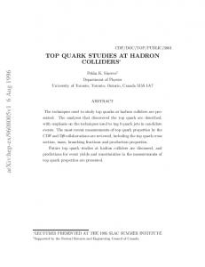
A future linear e+ e− collider offers the cleanest conditions for studying top quark properties, such as the top quark mass, its vector and axial couplings, and possible magnetic and electric dipole moments. Apart from these static properties, also the polarization of the top quark can be studied with great precision. The top decays sufficiently fast so that hadronization effects do not spoil the polarization which it has at its birth. The large number of top quark pairs expected to be produced at the ILC, e.g., 50 (tt¯)/hour at 500 GeV (based on a luminosity of L = 2 × 1034 cm−2 s−1 [1, 2]), will enable one to precisely determine the top quark polarization from an angular analysis of its decay products in the dominant decay t → Xb + W + . The expected statistical errors in the angular analysis are below the 1% level. Therefore very precise measurements of the angular distributions and correlations of the decay products of t and t¯ will shed light on the polarization of the top quarks and on the spin–spin correlations of the top and antitop quark pairs which are imprinted on the top and antitop quarks by the (tt¯)-production mechanism. In addition, the measurement of the top polarization will make it possible to precisely determine the electroweak Standard Model (SM) parameters or to study a variety of new phenomena beyond the SM. It is well known that the top quarks from e+ e− annihilations are polarized even for unpolarized e+ e− beams due to the presence of parity-violating interactions in the Standard Model (SM). One also knows from the work of Ref. [3, 4] that the polarization of the top quark in polarized e+ e− annihilations can become quite large when the beam polarization is adequately tuned. This is illustrated in Fig. 1 where we display the energy dependence of the mean longitudinal and transverse polarization of the top quark in the helicity system for different values of the effective polarization Peff defined by Peff =
h− − h+ . 1 − h− h+
(1)
In Eq. (1), h− and h+ are the longitudinal polarization of the electron and positron beams, respectively. Note that, for unpolarized positron beams h+ = 0, one has Peff = h− . For a given value of h− , even small values of positron polarization of opposite sign will enhance the effective beam polarization. We shall return to this point in Sec. 2. As compared to the work of Ref. [3], Fig. 1 now includes the O(αs ) radiative corrections. Large singlespin polarization effects due to beam polarization effects are also implicit in the work of Parke and Shadmi [5]. Although Ref. [5] is designed for the analysis of top–antitop quark spin correlations, it is easily adapted to single-spin polarization effects as also discussed in Ref. [6]. We shall see that the polarization of the top quark is governed by three parameters: q the velocity v = 1 − 4m2 /s, the effective polarization Peff , and the cosine of the scattering angle cos θ. At the respective boundaries of the three parameters the description 2
(a)
(b) Figure 1: Average (a) longitudinal polarization hP (ℓ) i and (b) transverse polarization √ hP (tr) i as a function of the c.m. energy s, for the values Peff = −1 (dashed), Peff = −0.5 (dash-dotted), Peff = 0 (solid), Peff = +0.5 (dash-dotted), and Peff = +1 (dashed). Averaging is over cos θ.
3
of the polarization phenomena becomes reasonably simple, in particular, at the Born term level. The limits v = 0 (threshold) and v = 1 (high-energy limit) are discussed in Sec. 4. In Sec. 5 we discuss the limiting cases Peff = ±1. The two respective limiting cases v = 0, 1 and Peff = ±1 contain in a nutshell much of the information that we want to discuss in the remaining part of the paper for intermediate values of these parameters. Many of the qualitative features of our results can be understood from extrapolations away from the two respective limits. We shall also address the question of how to maximize and minimize the polarization of the top quark by tuning the beam polarization. Whereas a maximum polarization is optimal for the experimental determination of polarization effects, it is often desirable to gauge the quality of a polarization measurement against the corresponding unpolarized decay analysis. For some measurements it may even be advantageous to eliminate polarization effects altogether. Of course, in the tuning process one has to bear in mind to keep the production rate at an acceptable level. This problem is not unrelated to the one of the original motivations of including beam polarization in linear colliders, namely, the gain in rate through beam polarization effects. We shall also address this question. Our paper is structured as follows. In Sec. 2 we present the spin formalism of polarized beam production of top–antitop quark pairs including the polar angle dependence of the various spin components and longitudinal beam polarization effects. We present Born term and loop formulas for the relevant structure functions and collect general expressions necessary for the numerators and the denominator of the polarization observables. Section 3 contains numerical next-to-leading (NLO) results on the angle-integrated rate and on polar angle distributions of the rate including beam polarization effects. We also provide numerical results on the left–right polarization asymmetry ALR . In Sec. 4 we discuss the limiting cases v = 0 and v = 1 at the Born term level. In Sec. 5 we describe the simplifications that occur for maximal effective beam polarizations Peff = ∓1 which + correspond to the (e− L/R , eR/L ) beam configurations. In Sec. 6 we discuss beam polarizations effects on the three components of the top quark polarization vector. Section 7 contains a discussion of the magnitude and the orientation of the polarization vector of the top quark. In Sec. 8 we present numerical NLO results on beam polarization effects on longitudinal spin–spin correlations of the top and antitop quark. Finally, Sec. 9 contains a summary of our results and our conclusions. In an Appendix we list the electroweak coupling coefficients used in this paper and relate them to the chiral electroweak coupling coefficients used e.g. in Ref. [5]. Many of the quantitative arguments presented in this paper are based on Born term √ level results for which we give explicit alpha-numerical expressions for s = 500 GeV. We emphasize, though, that all numerical results presented in the plots include the full O(αs ) radiative corrections where we have integrated over the full gluon phase space. 4
By comparing the graphical NLO results with the numerical LO results, one can assess the size of the O(αs ) radiative corrections, at least for the representative energy of √ s = 500 GeV. In general, the O(αs ) corrections to polarization observables are small (up to several percent) but can become much larger in some areas of phase space. A case in point is the longitudinal polarization of the bottom quark produced on the Z 0 at the backward point which obtains a 25% O(αs ) correction when Peff = +1 [4]. As we shall see later on, the O(αs ) corrections to (tt¯)-production can amount up to 12% (see Sec. 7). In addition, there are polarization observables that are zero at the Born term level and become populated only at O(αs ). Among these are the normal component of the polarization (see Sec. 6) and the longitudinal polarization produced from a longitudinal intermediate vector boson (see Sec. 2).
2
Spin formalism of polarized beam production
The production of top quark pairs at a linear e+ e− -collider proceeds via γ- and Zexchange, γ ,Z e− e+ → tt¯. (2) At the center of mass energies which are being envisaged at the ILC (s = (pe− + pe+ )2 ), √ s ∼ 2mt ÷ 1000 GeV, top quark pairs will be produced with nonrelativistic velocities in the threshold region (v → 0)qup to relativistic velocities of v = 0.937 at the highest √ energy s = 1000 GeV (v = 1 − 4m2t /s).1 This enables the study of the complete production phenomena with different polarization and correlation effects that reach from the nonrelativistic to the relativistic domain. For unpolarized beams the total rate is dominated by the diagonal (γ – γ) and the (Z – Z) rates which contribute at the same order of magnitude. The (γ – Z) interference contribution to the total rate is suppressed due to the smallness of the vector (Z e+ e− ) coupling vl (vl = −1 + 4 sin2 θW ). The (γ – Z) interference contribution can, however, become quite sizable for polarized beams, for the polar angle dependent rates and for top quark polarization effects. We mention that, at threshold, there will be the opportunity for very precise measurements of the top quark mass and width, as well as of the strong coupling αs . In this region, perturbative QCD is no longer applicable. One has to solve the Schr¨odinger equation for the relevant Green functions in a nonrelativistic approximation for a Coulombic potential, i.e. the nonrelativistic QCD (NRQCD) method, described first in Ref. [8] and later applied to the calculation of various different quantities at threshold (see for example the discussion in Ref. [9, 10] and references therein). In this paper we shall discuss top–antitop production well above threshold where perturbation theory can be safely applied. For our purposes we take the perturbative regime to start approximately 10 GeV 1
In the first stage of the ILC, one will reach energies up to 500 GeV with an optional second stage upgrade to 1000 GeV [1, 2]. For the multi-TeV collider CLIC one foresees energies up to 3 TeV [7].
5
above threshold. Throughout this paper we shall take the top quark mass to have a nominal value of 175 GeV. Therefore, we shall consider c.m. beam energies starting from √ s = 360 GeV. We are going to discuss the most general case of the polarization of the top quark with arbitrary longitudinal polarizations of the e− - and e+ -beams. The rate depends on the set of four parameters {h− ∈ [−1, 1], h+ ∈ [−1, 1], v ∈ [0, 1], cos θ ∈ [−1, 1]} or, equivalently, on the set {KG ∈ [0, 2], Peff ∈ [−1, 1], v ∈ [0, 1], cos θ ∈ [−1, 1]}, where we shall call KG = 1 − h− h+ the gain factor. We have indicated the range of the parameter values in square brackets. In contrast to the rate, the polarization of the top quark depends only on the set of the three parameters {Peff , v, cos θ}. When discussing our predictions we shall attempt to explore the whole four- and three-dimensional parameter space for the rate and polarization, respectively. We mention that the beam polarizations envisaged at the ILC are h− = ±90% for electrons and h+ = ±80% for positrons [11]. We will see that beam polarizations significantly influence the polarization phenomena of a top quark. In addition, adequately tuned beam polarization can enhance the top–antitop quark signal and suppress other background processes such as W -pair production (see discussion in Ref. [12]). In what follows, we concentrate on the polarization of the top quark, i.e. we sum over the polarization of the antitop quark. The polarization of the antitop quark can be obtained from the corresponding polarization components of the top quark using CP invariance as will be discussed in the summary section. Even more structure is revealed when one considers joint top-antitop polarization. In order to reveal this structure, one must perform a joint analysis of the decay products of the top and antitop quark. (tt¯) spin–spin correlations will be briefly discussed in Sec. 8 at the end of the paper. The general expression of the cross section for (tt¯) production in e+ e− collisions is given by2 4 e4 X j(m) (m) gij Li µν Hµν dP S . (3) dσ = 2π 2 s i,j=1 j Liµν is the lepton tensor, Hµν is the hadron tensor encoding the hadronic production dynamics, dP S is the phase space factor, and the gij are the elements of the electroweak coupling matrix which are defined in the Appendix. The sum runs over the four independent configurations of products of the vector and axial vector currents, i.e. i, j = 1, 2 for (V V ± AA)/2, i, j = 3 for i(VA − AV )/2, and i, j = 4 for (VA + AV )/2 for the product of lepton and quark currents, and m denotes one of the possible polarization configurations of the top quark: longitudinal (m = ℓ), transverse (m = tr) in the beam scattering plane and normal (m = n) to the beam scattering plane. Our choice of the 2
The spin kinematics of e+ e− collisions has been formulated in a number of papers. These include the unpublished DESY report [13] of which the portions relevant to this paper have been summarized in Ref. [14]. Other papers on the subject are Refs. [4, 12, 15, 16, 17, 18].
6
x α t t
e e−
(tr)
e (l)
Θ
e+ R
L
z
t
Figure 2: A generic configuration for top pair production and top polarization at a + polarized e+ e− collider with a (e− L , eR ) polarization. The positive z axis points into the direction of the electron momentum. The angle α is the polar angle of the top quark polarization relative to the top quark momentum measured anticlockwise from the direction of the top quark. three orthonormal spin directions (~e (tr) , ~e (n) , ~e (ℓ) ) are given by ~e (tr) =
(~pe− × ~pt ) × p~t , |(~pe− × p~t ) × p~t |
~e (n) =
p~e− × p~t , |~pe− × p~t |
~e (ℓ) =
p~t . |~pt |
(4)
In Fig. 2 we have drawn the directions of ~e (tr) and ~e (ℓ) for a generic top quark direction; the vector ~e (n) shows out of the plane. For the unpolarized top quark case the superscript (m) is dropped in Eq. (3). The explicit definitions for all the above quantities together with explicit analytical expressions for the radiative corrections can be found in Refs. [14, 19, 20, 21] (see also Ref. [4]). We proceed with the discussion in the helicity basis, i.e. we take the direction of the top quark to define the z direction of the hadronic system. For unpolarized beams the angular decomposition of the differential polarized cross section can be written as 3 3 3 dσ (m) (ℓ) (ℓ) (ℓ) = (1 + cos2 θ)σU + sin2 θσL + cos θσF d cos θ 8 4 4 3 3 (tr,n) (tr,n) − √ sin θ cos θσI − √ sin θσA , 2 2
(5)
where, at NLO of QCD, σa(m) =
4 πα2 v X g1j (Haj(m) (Born) + Haj(m) (αs )) 3s2 j=1
σa(m) =
4 πα2 v X g4j (Ha4(m) (Born) + Ha4(m) (αs )) 3s2 j=1
and
7
for a = U, L, I
(6)
for a = F, A .
(7)
In Eq. (5) we have rewritten the covariant representation (3) in terms of helicity structure functions σa(m) . The angle θ is the polar angle between the momentum of the top quark and the electron momentum (see Fig. 2). For example, in the purely electromagnetic case e+ e− → γ ∗ → q q¯ one obtains the LO formula 2� � dσ 2 α 1 + cos2 θ + (1 − v 2 ) sin2 θ = 2πNc Qf v cos θ 4s
(8)
using the LO born term expressions listed later in Eq. (10). The distribution (8) agrees with Eq. (41.2) in the PDG booklet. We mention that our O(αs ) corrections agree with those in Ref. [4] after correcting a sign mistake in the normal polarization (see Erratum in Ref. [21]). Above the top quark threshold, one is sufficiently far away from the Z-boson pole to neglect the imaginary part of the Z boson pole propagator. This can be appreciated from the Breit-Wigner line shape of the Z propagator, viz. χZ =
1 MZ ΓZ �.� MZ2 Γ2Z � 1 � 1 − i 1 + . = s − MZ2 + iMZ ΓZ s − MZ2 s − MZ2 (s − MZ2 )2
(9)
The factor MZ ΓZ /(s − MZ2 ) determines the ratio of the imaginary and real parts of the Z propagator Im χZ / Re χZ . It is already quite small at threshold (∼ 0.002) and falls off with s−1 . Dropping the imaginary part contribution of the Z propagator implies that we neglect contributions proportional to g13 in Eq. (6) and g43 in Eq. (7). We shall also neglect the width dependence in the real part of the Z propagator because it is negligibly small. The nonvanishing unpolarized Born term contributions Haj (Born) read HU1 (Born) = 2Nc s(1 + v 2 ),
HL1 (Born) = Nc s(1 − v 2 ) = HL2 (Born),
HU2 (Born) = 2Nc s(1 − v 2 ),
HF4 (Born) = 4Nc sv.
(10)
One has (1 − v 2 ) = 4m2t /s showing that the longitudinal rate HL falls off with a s−1 power behaviour relative to the transverse rates HU,F . The longitudinally polarized contributions read 4(ℓ)
HU (Born) = 4Nc sv, 4(ℓ)
HL (Born) = 0,
1(ℓ)
HF (Born) = 2Nc s(1 + v 2 ), 2(ℓ)
HF (Born) = 2Nc s(1 − v 2 ).
(11)
Note that one has the Born term relations 4(ℓ)
HU (Born) = HF4 (Born) , 1,2(ℓ)
HF
(Born) = HU1,2 (Born) ,
(12)
which are due to angular momentum conversation in the back-to-back configuration at the Born term level. It is quite clear that Eqs. (12) no longer hold true in general at 8
O(αs ) since quark and antiquark are no longer back-to-back in general due to additional gluon emission. The relations (12) will be useful in our subsequent discussion of the longitudinal polarization at the forward and backward points. Notable also is the relation 4(ℓ) HL (Born) = 0 in Eq. (11) which is again related to the LO back-to-back configuration. (ℓ) The radiative corrections to the corresponding polarization component PL have been studied in Ref. [20] and have been found to be small of O(0.1%) when averaged over (ℓ) gluon phase space. For small top quark energies PL can become as large as 3% at √ s = 500 GeV. For the transverse polarization components, one has [21] 4(tr)
HI
mt (Born) = 2Nc sv √ , 2s
1(tr)
HA
mt 2(tr) (Born) = 2Nc s √ = HA (Born) . 2s
(13)
The only nonnegligible contribution to the normal polarization component P (n) comes from the imaginary part of the one-loop contribution (CF = 4/3) mt αs C F 2(n) πv √ = HI (loop) , 4π 2s mt α C s F 4(n) π(2 − v 2 ) √ . HA (loop) = 2Nc s 4π 2s 1(n)
HI
(loop) = 2Nc s
(14) (15)
As already mentioned in the Introduction, the transverse and normal polarization compo√ nents can be seen to fall off with a power behaviour of ( s)−1 relative to the longitudinal polarization components. The αs corrections to the polarized structure functions Haj(m) = Haj (+sm ) − Haj (−sm ) and the unpolarized structure function Haj = Ha (+sm )+Ha (−sm ) (sm is the polarization vector of the top quark) are too lengthy to be listed here. They can be found in Refs. [14, 19, 20, 21], or, in a very compact two-page analytical representation, in Sec. 5 of Ref. [22]. The longitudinal polarization of the electron and positron beams enter the above formulas as [14]3 g1j → (1 − h− h+ )g1j + (h− − h+ )g4j = (1 − h− h+ )(g1j + Peff g4j ) ,
g4j → (1 − h− h+ )g4j + (h− − h+ )g1j = (1 − h− h+ )(g4j + Peff g1j ) ,
(16)
where Peff is defined in Eq. (1). In Eq. (16) h− denotes the electron’s and h+ denotes the positron’s longitudinal polarization which can take values between ±1. An electron with h− = ∓1 will be referred to as the totally polarized left-handed (right-handed) electron + (e− L/R ). Similarly, a right-handed positron (eR ) has h+ = −1 and a left-handed positron (e+ L ) has h+ = +1. From the definition of Peff (see Eq. (1)) it is clear that large values of Peff can be reached even for nonmaximal values of h− and h+ , as Fig. 3a shows. For 3
Transverse beam polarization effects will not be discussed in this paper because present plans call for longitudinal beam polarization at the ILC. Transverse beam polarization effects can be included as described e.g. in Ref. [14].
9
1.0 -0.95
-0.75
0.5
-0.5 -0.25
h+
0
0.0
0.25 0.5 -0.5
0.75
0.95 -1.0 -1.0
0.0
-0.5
0.5
1.0
h-
(a) 1.0 1.75
0.25 1.5
h+
0.5
0.5
1.25
0.0
1
1
1
1
-0.5
0.75
0.75
1.25 1.5
0.5
1.75
0.25 -1.0 -1.0
0.0
-0.5
0.5
1.0
h-
(b) Figure 3: Contour plots in the (h− , h+ )-plane (a) for fixed values of the effective polarization Peff = (h− − h+ )/(1 − h− h+ ) and (b) for fixed values of the gain factor KG = (1 − h− h+ ). The two points marked off in the plots correspond to (h− , h+ ) = (−0.8, +0.625) and (+0.8, −0.625), respectively.
10
example, the large value of Peff = −0.95 can be achieved with h− = −0.8; h+ = 0.625, and correspondingly, Peff = 0.95 can be reached with h− = 0.8; h+ = −0.625. These two examples have been marked off in Fig. 3. Both sets correspond to a gain factor of KG = 1.5. The orientation-dependent longitudinal, transverse, and normal polarization components which we are interested in are defined by P (m) (cos θ) =
dσ (m) /d cos θ dσ/d cos θ
m = ℓ, tr, n ,
(17)
where dσ/d cos θ is the unpolarized differential cross section. Of course, there is an √ additional dependence of the above quantities on the c.m. beam energy s, and on the beam polarizations h− and h+ to be discussed later on. The unpolarized cross section is given by the first three terms in Eq. (5) dropping, of course, the label (ℓ). Dropping the common factor πα2 v/(3s2 ) in the ratio (17), we shall represent the polarization components by the ratios P (m) (cos θ) =
N (m) (cos θ) , D(cos θ)
m = ℓ, tr, n.
(18)
In particular, the gain factor KG has canceled out in the ratio (18) implying that the polarization only depends on Peff . The numerator factors N (m) in Eq. (18) are given by N (ℓ) (cos θ) =
3 3 4(ℓ) 4(ℓ) (1 + cos2 θ) (g14 + g44 Peff )HU + sin2 θ (g14 + g44 Peff )HL 8 4 � � 3 1(ℓ) 2(ℓ) , (19) + cos θ (g41 + g11 Peff )HF + (g42 + g12 Peff )HF 4
3 4(tr) N (tr) (cos θ) = − √ sin θ cos θ (g14 + g44 Peff ) HI 2 � � 3 1(tr) 2(tr) − √ sin θ (g41 + g11 Peff )HA + (g42 + g12 Peff )HA , 2
(20)
and by � � 3 1(n) 2(n) N (n) (cos θ) = − √ sin θ cos θ (g11 + g41 Peff ) HI (loop) + (g12 + g42 Peff ) HI (loop) 2 3 4(n) − √ sin θ (g44 + g14 Peff ) HA (loop) . (21) 2
For the denominator, one has 3 (1 + cos2 θ) (g11 + g41 Peff )HU1 + (g12 + g42 Peff )HU2 D(cos θ) = 8 � � 3 2 1 2 + sin θ (g11 + g41 Peff )HL + (g12 + g42 Peff )HL 4 3 + cos θ (g44 + g14 Peff )HF4 . 4 �
11
�
(22)
At the forward (FP) and backward (BP) point the transverse and normal polarization components vanish. Referring to the relations (12), at Born term level the longitudinal polarization component P (ℓ) takes a very simple form at the forward (FP) and backward (BP) point for the maximal values of the effective polarization Peff = ±1. One has FP : BP :
P (ℓ) (cos θ = +1) = ±1 ,
P (ℓ) (cos θ = −1) = ∓1 ,
(23)
in agreement with angular momentum conservation. It is clear that these relations no longer hold true in general at NLO due to hard gluon emission. It is useful to define the left–right polarization asymmetry ALR through the relation dσ(Peff ) − dσ(−Peff ) = −ALR Peff , dσ(Peff ) + dσ(−Peff )
(24)
where ALR = −
3 (1 8 3 (1 8
�
�
�
�
+ cos2 θ) g41 HU1 + g42 HU2 + 43 sin2 θ g41 HL1 + g42 HL2 + 43 cos θg14 HF4 �
�
�
�
+ cos2 θ) g11 HU1 + g12 HU2 + 43 sin2 θ g11 HL1 + g12 HL2 + 34 cos θg44 HF4
(25) Of interest is the angle α enclosed by the momentum and the polarization of the top quark projected onto the scattering plane (see Fig. 2).4 The angle α is determined by tan α (cos θ) =
N (tr) (cos θ) . N (ℓ) (cos θ)
(26)
Equation (26) assumes a simple form at threshold and in the high-energy limit as discussed in Sec. 4, and for Peff = ±1 as will be discussed in Sec. 5. The correlations between α and θ implied by Eq. (26) will be discussed in Secs. 4, 5 and 7.
3
Beam polarization dependence of the rate
We begin our numerical discussion with the rate proportional to the denominator expression in Eq. (18). The effect of longitudinally polarized beams on the polar averaged rate (called total rate) can be obtained from the form
σ = σ(Peff
4
g42 HU2 +L 1+ g41 g41 HU1 +L , = 0) (1 − h− h+ ) 1 + Peff g12 HU2 +L g11 1+ 1 g11 HU +L
(27)
For the present purposes we neglect the O(αs ) normal component of the polarization vector which is quite small. Note that, in general, one needs two angles to describe the orientation of the polarization vector instead of the one angle α defined in Eq. (26).
12
which, at the Born level and at
√
s = 500 GeV, gives �
�
σ = σ(Peff = 0) (1 − h− h+ ) 1 − 0.37 Peff .
(28)
From Eq. (28) it is evident that the total rate becomes maximal on two counts: (i) large values of the gain factor KG = (1 − h− h+ ), requiring sign(h− ) = −sign(h+ ); and (ii) large negative values of Peff , which can be achieved with large negative and positive values of h− and h+ , respectively. The maximal enhancement of the rate will be obtained √ for h− = −1 and h+ = +1 such that Peff = −1 and KG = 2. At s = 500 GeV, this leads to a maximal enhancement factor of 2.74 over the unpolarized case. It is interesting √ to note that for (b¯b) production at s = 500 GeV the effective enhancement through beam polarization effects is slightly larger than in the (tt¯) case. For (b¯b) production the last factor in Eq. (27) is replaced by the simpler expression (1 + Peff g41 /g11 ) since, at √ s = 500 GeV, the ratio HU2 +L /HU1 +L is practically zero for bottom quark production. Using the results of the Appendix applied to the (b¯b) case, one finds g41 /g11 = −0.62 leading to an overall enhancement factor of 3.24 for the optimal choice of parameters √ h− = −1 and h+ = +1 (Peff = −1) at s = 500 GeV. In Fig. 3b we show some contour lines for fixed values of the gain factor KG = (1 − h− h+ ) in the (h− , h+ )-plane. Clearly, quadrants 2 and 4 are favoured if one wants to obtain a gain factor exceeding one, i.e. KG ≥ 1. As concerns the rate dependence on Peff (rightmost factor in Eq. (28)), a further rate enhancement is achieved for negative values of Peff , i.e. one would have to choose points lying to the left of the line h− = −h+ in Fig. 3a. The optimal choice as concerns the rate would thus be quadrant 2 in the (h− , h+ )-plane. One notes that large negative values of Peff can readily be achieved for nonmaximal values of the beam polarization, as illustrated in Fig. 3a, where we have plotted some contour lines in the (h− , h+ ) plane corresponding to fixed values of Peff . One notes that the regions of large KG and large negative Peff have a large overlap. We mention that one may have to give up the optimal choice in the (h− , h+ ) plane if one wants to achieve other goals such as minimizing the polarization. The QCD one-loop corrections to the total cross section are well-known (see e.g. √ Ref. [18]) and add about 13% at s = 500 GeV to the Born total cross section, where the percentage increase has very little dependence on the beam polarization. We mention that the electroweak corrections to the total rate are smaller, and amount to about 50% of the QCD corrections [23]. For the strong coupling αs we use two-loop running adjusted to the value αs (mZ ) = 0.1175 and fitted at 2mt = 350 GeV.5 Close to threshold the O(αs ) corrections become larger and amount to about 27% of the total cross section at √ e.g. s = 400 GeV. The c.m. energy dependence of the total cross section σ is shown in Figs. 4a and 4b. In Fig. 4a we take h+ = 0 and show the energy dependence of 5
For α we take the value α = 1/137. If one uses a running α, for example α = 1/128, the cross sections in Fig. 4 would increase by 14.6%.
13
1.0 0.5
h-
0.0
-0.5 -1.0 0.8
Σ@pbD
0.6 0.4 0.2 400 600!!!!
s @GeVD
800 1000
(a)
(b) Figure 4: The total cross section σ at the one-loop level as a function of the beam energy √ s and (a) the electron polarization h− (h+ = 0); (b) for three values of the positron polarization h+ = 0, 0.4, 0.6, and with the fixed electron beam polarization of h− = −0.9 (solid lines). In Fig. 4b we also show the respective LO rates (dashed lines).
14
the total cross section varying h− over its whole range [−1, +1]. One notes a strong dependence on h− apart from the standard falloff of the total cross section with beam energy. Since for h+ = 0 the gain factor KG is equal to 1 and since Peff = h− , the rate depends linearly on h− as displayed in Eqs. (27) and (28). The rate is largest for h− = −1 and then linearly drops to its lowest value at h− = +1. In Fig. 4b we show the energy dependence of the rate for the three pairs of beam polarizations (h− , h+ ) = (−0.9, 0), (−0.9, +0.4), (−0.9, +0.6). If one translates this into the (KG , Peff ) representation, one has (KG , Peff ) = (1, −0.9), (1.36, −0.96), (1.54, −0.97). The hierarchy of rates in Fig. 4b can be seen to be mostly determined by the gain factor KG in Eq. (27). Next we turn to the differential rate distribution with respect to cos θ. In order to illustrate the forward dominance of the differential cos θ-distribution we plot σ −1 dσ/d cos θ against cos θ. Note that the dependence on the gain factor KG = 1 − h− h+ drops out in the ratio. In Fig. 5a we plot the differential rate distribution for a fixed value of √ s = 500 GeV and for Peff = −1, 0, +1. One sees a pronounced forward dominance of the differential distribution which does not depend much on the value of Peff . In Fig. 5b √ we keep the effective beam polarization fixed at Peff = 0 and vary s through several √ values. At threshold s = 350 GeV one has a flat distribution σ −1 dσ/d cos θ = 0.5. When the energy is increased, the forward rate clearly dominates over the backward rate. The forward dominance becomes even stronger for increasing energies. Of related interest is the rate into the forward (F) and backward (B) hemispheres. √ Again, the gain factor KG drops out in the ratio. At s = 500 GeV, one numerically obtains +2.73 Peff = +1 hσiF hσiF 1 − 0.34 Peff = = . (29) +2.36 = 0 hσiB hσiB Peff =0 1 − 0.43 Peff +2.21 = −1
The mean forward rate hσiF clearly dominates over the mean backward rate hσiB . The dependence of the F/B rate ratio on Peff is not very pronounced. In Fig. 6 we plot the polar angle dependence of the NLO left-right polarization √ asymmetry ALR for different energies. At s = 360 GeV the cos θ dependence already starts to deviate from the flat Born term behaviour at threshold given by ALR = −(g41 + g42 )/(g11 + g12 ) = 0.409. The left-right polarization asymmetry ALR peaks toward the √ backward region and reaches ≈ 59% at the backward point for the highest energy s = 3000 GeV in Fig. 6.
4
Born term simplifications at threshold and in the high-energy limit
Before turning to the numerical analysis of the polarization of the top quark, in this section we shall first discuss Born term simplifications of the polarization of the top quark 15
(a)
(b) √ Figure 5: Polar angle dependence of the differential cross section for (a) s = 500 GeV √ and Peff = −1, 0, +1 and (b) Peff = 0 for beam energies s = 360 GeV (dotted line), 500 GeV (dashed line), 1000 GeV (dash-dotted line), and 3000 GeV (solid line)
16
Figure 6: Left–right polarization asymmetry ALR for (notation as in Fig. 5)
√
s = 360, 500, 1000, and 3000 GeV
at threshold and in the high-energy limit. In Sec. 5 we discuss Born term simplifications that occur for Pef f = ∓1. At threshold v → 0 and in the high-energy limit v → 1, the polarization expressions become quite simple. At threshold, the polarization of the top quark is parallel to the beam axis, regardless of the polar orientation of the top quark (see e.g. Ref. [24]). In fact, a large part of the beam polarization gets transferred to the polarization of the top quark at threshold. For the Born term contributions the top quark polarization at threshold can be calculated from Eqs. (19), (20) and (22) (see also Ref. [18, 25]). It is nominally given by6 Peff − ALR (30) n ˆ e− , P~ = 1 − Peff ALR
where ALR is the left-right beam polarization asymmetry (σLR − σRL )/(σLR + σRL ) at threshold (see Eq. (25)) and n ˆ e− is a unit vector pointing into the direction of the electron momentum. In terms of the electroweak coupling parameters gij (see the Appendix), the √ nominal polarization asymmetry at threshold s = 2mt is given by ALR = −(g41 + g42 )/(g11 + g12 ) = 0.409. The simplification at threshold arises from the fact that, from the four (L, S)V,A amplitudes (L, S)V,A = (0, 1)V , (2, 1)V , (1, 0)A , (1, 1)A describing the production of a spin-1/2 pair, only the S-wave amplitude (0, 1)V survives at threshold. The suffices V and A denote vector current (V) and axial vector current (A) production. Correspondingly, the combinations (g41 + g42 ) and (g11 + g12 ) contain only the vector 6
As discussed in Sec. 2, QCD binding effects significantly modify the naive threshold results in the threshold region.
17
current coupling on the quark side. The magnitude of the threshold polarization is given by Peff − ALR . |P~ | = 1 − Peff ALR
(31)
The threshold polarization is independent of cos θ, i.e. h|P~ |i = |P~ |. The polarization vanishes for Peff = ALR independent of cos θ.7 For Peff > ALR and Peff < ALR one ˆ e− , respectively, such that P (tr) = ∓|P~ | sin θ and has P~ = |P~ | n ˆ e− and P~ = −|P~ | n P (ℓ) = ±|P~ | cos θ. In particular, one has a 100% threshold polarization of the top quark for Peff = ±1 with P~ = ±ˆ ne− . Extrapolations away from Peff = ±1 are more stable for Peff = −1 than for Peff = +1 as the slope of Eq. (31) at Peff = ±1 shows. One has 1 ± ALR d|P~ | =± . dPeff 1 ∓ ALR
(32)
For Peff = −1 one has a slope of −(1 − ALR )/(1 + ALR ) = −0.42 while one has a much larger positive slope of (1 + ALR )/(1 − ALR ) = +2.38 for Peff = +1. This substantiates the statement made above and in Sec. 1 about the stability of extrapolations away from Peff = ±1. For example, keeping only the linear term in the Taylor expansion of Eq. (31), one has |P~ | = 0.98 for Peff = −0.95, while |P~ | drops to |P~ | = 0.88 for Peff = +0.95. For energies above threshold the slope Eq. (32) becomes energy and angle dependent. We do not show plots of the slope at higher energies. We have, however, checked numerically that the above statement about the stability of the |P~ | result at Peff = −1 against variations of Peff remains true at higher energies in the whole angular range, where the slope in the backward region has a tendency to be smaller than in the forward region. As mentioned above, minimal polarization |P~ | = 0 occurs for Peff = ALR = 0.409 for all values of cos θ. This again shows that an extrapolation away from Peff = −1 is more stable than an extrapolation from Peff = +1 since one is much closer to the polarization zero in the latter case. This observation will carry over to the Peff -dependence at higher energies. In Fig. 7a we show the threshold correlation of the angles α and θ for different values of Peff . Starting at Peff = −1 the two angles are related by α = 180◦ − θ up to the longitudinal polarization zero at Peff = ALR = 0.409 after which the correlation becomes α = −θ. As the beam energy increases, the polarization vector of the top quark slowly turns into the direction of its momentum (or opposite to it). Finally, in the high-energy limit s → ∞, when v → 1, the polarization of the top becomes purely longitudinal in the helicity system such that |P~ | = |P (ℓ) | since its transverse and normal components 7
Threshold simplifications for (q q¯) production have also been discussed in Ref. [26]. Similar simplifications for polarization observables occur for the threshold production of gauge boson pairs [27].
18
100
Α@degD
0
150
-100 100
-1.0
Θ@degD
-0.5 50
Peff0.0 0.5 1.0
0
(a)
100
Α@degD
0
150
-100 100
-1.0
Θ@degD
-0.5
Peff
50
0.0 0.5 1.0
0
(b) Figure 7: Correlation of the angles α and θ in dependence on the effective beam polar√ ization Peff (a) for threshold energies s = 2mt and (b) for s → ∞
19
√ involve a spin flip amplitude and thus vanish as mt / s. Note that, although P (tr) is √ asymptotically suppressed, it is still sizable at s = 1000 GeV as Fig. 1 shows. In fact, in the high-energy limit, one has P~ (cos θ) = P (ℓ) (cos θ) · pˆt with P (ℓ) (cos θ) = (g14 + g41 + Peff (g11 + g44 ))(1 + cos θ)2 + (g14 − g41 − Peff (g11 − g44 ))(1 − cos θ)2 (g11 + g44 + Peff (g14 + g41 ))(1 + cos θ)2 + (g11 − g44 − Peff (g14 − g41 ))(1 − cos θ)2 (33) for the surviving longitudinal polarization. In the same limit, the electroweak coupling coefficients take the numerical values g11 = 0.601, g14 = −0.131, g41 = −0.201, g44 = 0.483, g12 = 0.352, and g42 = −0.164. When Peff = −1 it is more convenient to switch to the chiral electroweak coefficients fLL/LR defined in the Appendix. One has (fLL = −1.190; fLR = −0.434) P
(ℓ)
1 − bLR (cos θ) = − 1 + bLR
with
bLR =
fLR fLL
!2
(1 − cos θ)2 . (1 + cos θ)2
(34)
P (ℓ) goes through zero for bLR = 1 which is solved by cos θ = −(fLL − fLR )/(fLL + fLR ). For Peff = +1 one has a similar simplification where the quantities on the right-hand side of Eq. (34) are replaced by bLR → bRL and fLL/LR → fRR/RL (fRR = −0.867; fRL = −0.217). In this case P (ℓ) goes through zero for bRL = 1, or for cos θ = −(fRR − fRL )/(fRR + fRL ). At threshold the rate shows no cos θ dependence since the (tt¯) pair is produced in a S-wave state. This is different in the high-energy limit when v = 1, where the forward rate strongly dominates over the backward rate, as an inspection of the denominator of Eq. (33) shows. Since an accurate measurement of the polarization observables requires large statistics, and thus large event samples, the issue of rates is an important one. Numerically, one finds σ(cos θ = +1)/σ(cos θ = −1) = 9.23 (1 − 0.31Peff )/(1 − 0.60Peff ). The dependence on Peff is small. When averaging over the forward (F ) and backward (B) hemispheres, one finds hσiF /hσiB = 4.04 (1 − 0.31Peff )/(1 − 0.43Peff ), i.e. in the case of unpolarized beams when Peff = 0 the rate in the forward hemisphere dominates over the rate in the backward hemisphere by a factor of four with only slight dependence on beam polarization. Comparing to Eq. (29) the forward dominance is more pronounced √ in the high-energy limit than at s = 500 GeV. Equation (33) also very nicely shows how varying Peff affects the longitudinal polarization P (ℓ) . For the unpolarized beam case Peff = 0 the longitudinal polarization P (ℓ) is negative (−31%) at the forward point (FP) cos θ = +1 and positive (+60%) at the backward point (BP) cos θ = −1. For maximally polarized beams P eff = ±1, Eq. (33) can be seen to satisfy the angular momentum conservation conditions, Eq. (23). For P eff = ±1 the longitudinal polarization monotonically increases/decreases from the backward to the forward point. It can be seen to go through zero at cos θ = (g11 −g41 −g12 +g42 )/(g14 −g44 ) = 20
−0.47 ( ≃ 117.8◦) for Peff = −1 and cos θ = −(g11 +g41 −g12 −g42 )/(g14 +g44 ) = −0.60 ( ≃ 126.9◦ ) for Peff = +1 (see discussion after Eq. (34)). Close to Peff = ±1, the longitudinal polarization zeros are only mildly dependent on Peff . There is a range of Peff values for which the longitudinal polarization remains positive over the whole cos θ range. This is determined by the zeros of the coefficients of the angular factors in the numerator of Eq. (33). The condition for positivity of P (ℓ) reads −
g14 − g41 g14 + g41 < Peff < . g11 + g44 g11 − g44
(35)
Numerically this translates into 0.31 < Peff < 0.60. The same bounding values determine the vanishing of the polarization at the forward and backward points. At the forward point, where the rate is highest, the polarization |P~ | can be made to vanish by setting Peff = −(g14 + g41 )/(g11 + g44 ) = 0.31. At the backward point, one has zero longitudinal polarization for Peff = (g14 − g41 )/(g11 − g44 ) = 0.60. All of this is illustrated in Fig. 7b showing the correlation between Peff and the angles α and θ. The steplike behaviour in Fig. 7b is associated with the vanishing of the polarization at which points the polarization vector changes its direction by 180◦. At Peff = −1 the polarization vector P~ is antiparallel to ~pt up to where P~ becomes zero at θ ∼ 117.8◦ . From then on P~ is parallel to p~t . Zero polarization and the location of the step-like behaviour is slightly Peff -dependent and is shifted to lower values of α. For 0.31 < Peff < 0.60 the polarization P~ is always parallel to p~t . Finally, for Peff = +1 the polarization P~ starts off parallel to ~pt and turns antiparallel to p~t after the zero at cos θ ≃ 126.9◦ . Again the polarization zero and the associated step-like behaviour is slightly shifted when one moves away from Peff = +1. Given the fact that the polarization turns from the beam direction to the momentum direction (or its opposite) going from threshold to the high energy limit it would be interesting to know how fast this transition occurs when the beam energy is ramped up √ in the envisaged range of beam energies s ∼ 2mt ÷ 1000 GeV. In Fig. 8 we investigate the energy dependence of the angle α for several values of Peff for a scattering angle of θ = 90◦ . In Fig. 8a we consider three representative negative values of Peff . All three curves start off with the threshold angle α = 90◦ . The growth of α does not depend √ much on Peff but is still far away from the asymptotic value α = 180◦ at s = 1000 GeV. For positive values of Peff the dependence of α on Peff is more pronounced (see Fig. 8b). For Peff = +1 and Peff = +0.5, one is getting closer to the asymptotic value of α = 0◦ √ at s = 1000 GeV than for the negative values of Peff shown in Fig. 8a. The behaviour of the Peff = +0.25 curve differs from the two other curves since one has crossed a longitudinal polarization zero between Peff = +0.5 and Peff = +0.25.
21
(a)
(b) Figure 8: The top quark polarization angle α for a scattering angle of θ = 90◦ as a function of the beam energy for (a) negative values of Peff = −1, −0.5, −0.25 and (b) positive values of Peff = +1, +0.5, +0.25
22
5
Born term simplifications for Peff = ∓1
As has been emphasized in the notable paper by Parke and Shadmi [5], the Born term polarization formulas considerably simplify for the case of maximal effective beam polar+ ization Peff = −1 which corresponds to a (e− L , eR ) configuration. Although designed for the case of top–antitop spin–spin correlations, the results of Ref. [5] are easily adopted to the case of single-spin polarization as also noted in Ref. [6]. From a practical point of view the limiting case Peff = −1 is very interesting since, as was emphasized in Sec. 2, one can get quite close to the maximal value Peff = −1 even if the beam polarizations are not close to their maximal values. Similar simplifications occur for the case Peff = +1. In order to distinguish between the two cases we add the suffices LR and RL for quantities derived for the case Peff = −1 and Peff = +1, respectively. For the Born term case and in the limit Peff = −1, the polarized numerators (19) and (20) take a factorized form, 3 = − fLL (cos θ + v) + fLR (cos θ − v) ALR (cos θ) 2Nc s , 8 √ 3 (tr) sin θ 1 − v 2 (fLL + fLR ) ALR (cos θ) 2Nc s , NLR (cos θ) = 8 �
(ℓ) NLR (cos θ)
�
(36) (37)
where the common factor ALR (cos θ) is given by ALR (cos θ) = fLL (1 + v cos θ) + fLR (1 − v cos θ) .
(38)
We have made use of the chiral electroweak coupling coefficients fLL/LR of Ref. [5] which are simply related to our electroweak coupling factors gij (see the Appendix). One can (ℓ) check that one can obtain NLR (cos θ) in Eq. (36) from the generic spin formula Eq. (1) of Ref. [5] when one specifies to the helicity system with cos ξ = +1. Similarly, one obtains (tr) NLR (cos θ) in Eq. (37) when one specifies to the transversity system cos ξ = 0. In each of the two respective systems, one has to take the cross section difference σ(t ↑) − σ(t ↓). One can then determine the angle α enclosing the direction of the top quark and its polarization vector by taking the ratio N (tr) /N (ℓ) . One has √ sin θ 1 − v 2 (fLL + fLR ) . = (ℓ) =− fLL (cos θ + v) + fLR (cos θ − v) NLR (cos θ) (tr)
tan αLR
NLR (cos θ)
(39)
For example, at threshold (v = 0) one has tan αLR = − tan θ with the solution αLR = 180◦ −θ in agreement with the corresponding limit in Sec. 4. As another example we take √ √ θ = 90◦ and obtain tan αLR = −(fLL + fLR )/(fLL − fLR ) · 1 − v 2 /v. For s = 500 GeV this gives αLR = 124.9◦, i.e. the polarization vector is still close to its threshold value of αLR = 90◦ but has started to turn to its asymptotic value of αLR = 180◦ . Equation (39) is nothing but the defining equation for the off-diagonal basis in Ref. [5] considering the fact that their angle ξ is related to αLR by ξ = 180◦ − αLR . In the 23
coordinate system where the z axis is defined by the angle αLR given in Eq. (39), the polarization vector of the top quark is purely longitudinal. In particular, this means that its transverse component is zero in the off-diagonal basis implying that the density matrix of the top quark is diagonal in this basis. In this sense the “off-diagonal” basis is a diagonal basis and the wording “off-diagonal” used in Ref. [5] for this basis can lead to a misunderstanding. A different but equivalent view on the off-diagonal basis may be obtained by rotating the nondiagonal helicity system density matrix of the top quark (m, n = ±1/2) ρmn =
(ℓ)
1 1+P 2 P (tr)
(tr)
P 1 = (σ · 1l + ξ~ · ~ σ ). (ℓ) 2 1−P
(40)
in the scattering plane by an angle α. One has 1/2
1/2†
ρ′m′ n′ = dm′ m (α) ρmn dnn′ (α) =
(ℓ)
(tr)
(ℓ)
(tr)
P sin α − P cos α 1 1 + (P cos α + P sin α) (ℓ) (tr) 2 P sin α − P cos α 1 − (P (ℓ) cos α + P (tr) sin α) →
0 1 1 + |P~ | , 2 0 1 − |P~ |
(41)
√ 1/2 where dm′ m (α) is the usual spin-1/2 Wigner rotation matrix and |P~ | = P (ℓ)2 + P (tr)2 . It is evident that a rotation by the angle α = αLR defined in Eq. (39) diagonalizes the original density matrix as indicated in the last line of Eq. (41). The correlation between the angles α (for general values of Peff ) and θ are shown in the contour plots Fig. 9. In Fig. 9a we choose Peff = −1 and show fixed energy contours √ √ in the (α, θ)-plane for several values of the c.m. energy s. Up to s = 1000 GeV the correlations do not deviate very much from the threshold correlation α = 180◦ − θ. In the limit v = 1 one has a steplike behaviour of the correlation function as discussed before in Sec. 4. In Fig. 9b we show the same plots for Peff = +1. The approach of the correlation curves to the steplike behaviour at v = 1 is somewhat faster than in the case Peff = −1. In Fig. 9c we show the same curves for Peff = 0.5 where one is close to the √ polarization zero. The s = 360 GeV correlation curve is still close to the corresponding threshold curve α = −θ. At higher energies one sees a different behaviour in as much as the correlation curves run into α = 0◦ at the backward point as does the flat asymptotic curve as discussed before in Sec. 4 (Fig. 7). In order to calculate the normalized polarization components one needs also the denominator factor D(cos θ) in Eq. (22), again for the Born term case and Peff = −1. One has � 3� (42) DLR (cos θ) = A2LR − 2fLL fLR v 2 sin2 θ 2Nc s . 8 proportional to the cross section sum σ(t ↑) + σ(t ↓) in any of the systems in Ref. [5]. 24
(a)
(b)
(c) Figure 9: Correlation of angles α and θ for (a) Peff = −1 (α = αLR ), (b) Peff = +1 √ (α = αRL ), and (c) Peff = +0.5 for different values of the c.m. energy s = 360, 500, 1000, and 3000 GeV (notation as in Fig. 5)
25
(ℓ)
(ℓ)
Using Eqs. (36) and (42) the longitudinal polarization PLR = NLR /DLR can be seen to become maximally −1 and +1 in the forward and backward directions, respectively, in agreement with angular momentum conservation as before. One also reproduces the threshold formula Eq. (30) and the high-energy formula Eq. (33) when these are specified to Peff = −1. The longitudinal polarization goes through zero at cos θ0 = −
g14 − g44 fLL − fLR v= v fLL + fLR g11 − g41 + g12 − g42
( = −0.48v) .
(43)
At this value of cos θ the polarization vector of the top quark is orthogonal to its momentum. Later on we shall see that, at this point, P (tr) acquires its maximal value and |P~ | acquires its minimal value. Since the ratio (fLL − fLR )/(fLL + fLR ) is only mildly energy-dependent, the location of the zero is mainly determined by the velocity of the top quark, i.e. it moves towards the backward point when the energy is increased. For √ convenience we have added the s = 500 GeV value of the electroweak coupling ratio in brackets in Eq. (43). (tr) The transverse polarization PLR vanishes in the forward and backward directions due to angular momentum conservation, as is explicit in Eq. (37). It becomes maximal at the point where the longitudinal polarization goes through zero. This can be verified by an explicit calculation, viz. (tr)
d PLR = 0, d cos θ cos θ
(44)
0
where cos θ0 is given in Eq. (43). Whereas there are no illuminating expressions for the longitudinal and transverse polarization components for general values of the velocity v, the magnitude of the polarization |P~ | for Peff = −1 takes the simple form |P~LR | =
q
(ℓ)2
(tr)2
NLR + NLR DLR
=
√
1 − 4aLR = 1 − 2a2LR − 8a3LR − 18a3LR . . . , 1 − 2aLR
(45)
where the coefficient aLR depends on cos θ through aLR (cos θ) =
fLL fLR 2 v 2 ALR (cos θ)
sin2 θ .
(46)
The convergence of the expansion in Eq. (45) is rather slow except for very small values of aLR . Note that the expansion in Eq. (45) deviates from 1 only at O(a2LR ). At the forward and backward points where aLR = 0, one has |P~LR | = 1 as stated before. Between the forward and backward points the polarization remains reasonably large. For example, √ for s = 500 GeV the polarization never drops below |P~LR | = 0.95. Differentiating of Eq. (45) with respect to cos θ one can see that the minimum of |P~LR | occurs at the (ℓ) point where the longitudinal polarization PLR vanishes (see Eq. (43)), i.e. where the polarization is purely transverse. The high-energy limit of Eq. (45) is discussed in Sec. 4. 26
Figure 10: Difference ∆αLR = αLR (NLO) −αLR (LO) of NLO and LO polarization angles √ for s = 360, 500, 1000, and 3000 GeV (notation as in Fig. 5) + Similar simplifications occur for the case Peff = +1 which corresponds to the (e− R , eL ) configuration. This is effected by the replacement fLL → fRR and fLR → fRL with a (ℓ) corresponding change in the notation ALR , aLR → ARL , aRL . Further one has NRL = (ℓ) (tr) (tr) −NLR (fLL → fRR ; fLR → fRL ) and NRR = −NLL (fLL → fRR ; fLR → fRL ). The √ zero of P (ℓ) is now located at cos θ0 = −0.63v for s = 500 GeV, i.e. the zero is closer to the backward point than in the case Peff = −1. For θ = 90◦ the angle αRL can be √ √ calculated from tan αRL = −(fRR +fRL )/(fRR −fRL )· 1 − v 2 /v which, at s = 500 GeV, √ gives αRL = −48◦ . At cos θ = 0 and s = 500 GeV, one has aLR > aRL leading to + |P~LR | < |P~RL |, i.e. the (e− R , eL ) configuration leads to larger values of the polarization + than the (e− L , eR ) configuration at this point of parameter space. In Fig. 9b we show a √ contour plot in the (αRL , θ) plane for several values of the c.m. energy s. As is the case for the (αLR , θ) correlations, the (αRL , θ) correlations do not deviate very much from the √ threshold correlation α = −θ up to s = 1000 GeV. As a last point we discuss how the polarization angle αLR changes when going from LO to NLO. In Fig. 10 we show a plot of the cos θ dependence of the difference ∆αLR = αLR (NLO) − αLR (LO) for different energies. The maximal values of the difference occur at values of cos θ where the polarization vector is perpendicular to the top quark’s momentum, i.e. where αLR = 90◦ (see discussion after Eq. (43)). The difference √ can become as big as 10◦ for s = 3000 GeV. The radiative corrections can thus be seen to rotate the polarization vector away from the off-diagonal basis by a nonnegligible amount.
27
6
The polarization components P (ℓ), P (tr), and P (n)
We now turn to the numerical discussion of the three polarization components P (ℓ) , P (tr) , and P (n) keeping in mind the Born term simplifications for P (ℓ) and P (tr) discussed in Secs. 4 and 5. We start our discussion with the longitudinal component P (ℓ) . In Fig. 11a we show the dependence of the NLO longitudinal polarization P (ℓ) on cos θ at √ s = 500 GeV for several values of Peff spanning the whole parameter range of Peff . The dependence of P (ℓ) on Peff and cos θ is quite pronounced. For Peff = ±1 the cos θdependence already deviates considerably from the (Born term) threshold behaviour P (ℓ) = ± cos θ. It is quite interesting to observe that all NLO curves intersect at one point where cos θ = −0.406. This can be verified by setting to zero the derivative of P (ℓ) with respect to Peff . The relevant higher order equation admits of a solution at the above value of cos θ. In Fig. 11b we show the cos θ-dependence of P (ℓ) for several energies keeping Peff fixed at Peff = −1. At the resolution of the figure all curves seemingly go through −1 and +1 at the forward and backward point, respectively, showing that hard gluon emission effects are not very strong at these energies. The energy dependence is not √ very pronounced, even if the s = 500 GeV curve already deviates from the threshold behaviour P (ℓ) = − cos θ. The strong dependence of P (ℓ) on Peff can be nicely exposed by considering the LO expression for the polar mean hP (ℓ) i which is obtained by integrating the numerator and the denominator in Eq. (18) separately over cos θ. One obtains hP (ℓ) i =
4 g14 + g44 Peff hN (ℓ) i = v . hDi 3 (g11 + g41 Peff )(1 + v 2 /3) + (g12 + g42 Peff )(1 − v 2 )
(47)
hP (ℓ) i vanishes at threshold. In the high-energy limit, one has hP (ℓ) i = (g14 +g44 Peff )/(g11 + g41 Peff ) which, for Peff = ±1, gives hP (ℓ) i = 0.882 and hP (ℓ) i = −0.766 close to the √ √ s = 1000 GeV values in Fig. 1. At s = 500 GeV, one has
hP (ℓ) i = hP (ℓ) i(Peff = 0)
1 − 3.61 Peff 1 − 0.37 Peff
+0.62 = −0.15 −0.50
Peff = +1 = 0 = −1
.
(48)
One observes a strong dependence of the mean longitudinal polarization on Peff . By √ comparing with the s = 500 GeV point in Fig. 1a, one observes a 2% change in hP (ℓ) i due to the radiative corrections. The same strong dependence on Peff is found when one averages over the forward √ hemisphere where one has ( s = 500 GeV)
hP (ℓ) iF = hP (ℓ) iF (Peff = 0)
1 − 3.09 Peff 1 − 0.34 Peff 28
+0.85 = −0.27 −0.81
Peff = +1 = 0 = −1
.
(49)
(a)
(b) Figure 11: NLO longitudinal top polarization as a function of cos θ drawn (a) for effective √ beam polarizations Peff = −1, −0.5, 0, +0.5, +1 (notation as in Fig. 1) at s = 500 GeV; √ (b) at beam energies s = 360, 500, 1000, and 3000 GeV (notation as in Fig. 5) and Peff = −1
29
(a)
(b) Figure 12: Average (a) longitudinal polarization hP (ℓ) i and (b) transverse polarization hP (tr) i in the forward and backward hemispheres for Peff = −1
30
When one averages over the backward hemisphere the average longitudinal polarization is smaller and the dependence on Peff is much weaker viz. hP (ℓ) iB = hP (ℓ) iB (Peff = 0)
1 − 1.04 Peff 1 − 0.43 Peff
−0.01 = +0.13 +0.18
Peff = +1 = 0 = −1
.
(50)
In Fig. 12a we show a plot of the energy dependence of the forward and backward averages of the longitudinal polarizations for Peff = −1. The forward average hP (ℓ) iF is large and negative. It starts with a nominal threshold value of hP (ℓ) iF = −0.5 and √ slowly drops to a value of hP (ℓ) iF = −0.90 at s = 1000 GeV which is not far from 2 2 2 2 the asymptotic Born term value hP (ℓ) iF = −(7fLL − fLR )/(7fLL + fLR ) = −0.96. The (ℓ) backward average hP iB is smaller and positive. It drops from a nominal threshold √ value of hP (ℓ) iB = +0.5 to hP (ℓ) iB = +0.14 at s = 1000 GeV as compared to the 2 2 2 2 asymptotic Born term value hP (ℓ) iB = −(fLL − 7fLR )/(fLL + 7fLR ) = −0.04. (tr) We now turn to the transverse polarization component P . Similar to Figs. 11a and 11b we show the corresponding curves for P (tr) in Figs. 13a and 13b. The transverse polarization vanishes at the end points due to the overall sin θ factor in the angular decay distribution Eq. (20). The dependence on Peff is again quite pronounced. One observes a faster change with Peff at Peff = +1 than at Peff = −1. P (tr) vanishes close to Peff = +0.5. √ √ At s = 500 GeV the deviations from the threshold behaviour P (tr) = ± 1 − cos θ2 √ for Peff = ±1 are slight but clearly visible. The ( s)−1 dependence of the transverse polarization is easily discernible in Fig. 13b. A visual inspection shows that, as is exact in the Born term case for Peff = ±1, the NLO longitudinal and transverse polarization components are complementary in the sense that the transverse polarization becomes maximal very close to the point where the longitudinal polarization becomes minimal, and vice versa. This observation bodes well for the existence of large values of the total polarization as discussed in Sec. 7. For the mean value of the transverse polarization, one obtains the Born term level expression g41 + g42 + (g11 + g12 )Peff π mt . hP (tr) i = − √ 2 s (g11 + g41 Peff )(1 + v 2 /3) + (g12 + g42 Peff )(1 − v 2 )
(51)
At nominal threshold one has hP (tr) i = ∓π/4 for Peff = ±1 close to what is seen in √ √ Fig. 1. In the high energy limit hP (tr) i vanishes as ( s) −1 . At s = 500 GeV one has hP (tr) i = hP (tr) i(Peff = 0)
1 − 2.53 Peff 1 − 0.37 Peff
−0.57 = +0.24 +0.61
Peff = +1 = 0 = −1
,
(52)
√ showing again the large effect of beam polarization. By comparing with the s = 500 GeV point in Fig. 1b, one observes a 1.5% change in hP (tr) i due to the radiative corrections. 31
(a)
(b) Figure 13: NLO transverse top polarization as a function of the scattering angle θ drawn (a) for effective beam polarizations Peff = −1, −0.5, 0, +0.5, +1 (notation as in Fig. 1) at √ √ s = 500 GeV; (b) at beam energies s = 360, 500, 1000, and 3000 GeV (notation as in Fig. 5) and Peff = −1
32
For the ratio of the forward and backward mean of the transverse polarization, one obtains +0.54 P = +1 eff (tr) (tr) hP iF hN iF hσiB , (53) = = +0.53 = 0 hP (tr) iB hN (tr) iB hσiF +0.61 = −1
There is a slight dominance of the backward mean as also evident in Fig. 13. The dependence of the ratio (53) on Peff is not very pronounced. A plot of the energy dependence of the forward and backward averages of the transverse polarization is shown in Fig. 12b. Both curves start at the nominal threshold value hP (tr) iF = hP (tr) iB = π/4 and then quite slowly begin their descent to their asymp√ totic demise. At s = 500 GeV and Peff = −1, one can compare the NLO result for hP (tr) iF /hP (tr) iB = 0.68 with the corresponding LO result hP (tr) iF /hP (tr) iB = 0.61 in Eq. (53). The normal polarization component P (n) is a T -odd observable and thus obtains only contributions from the imaginary parts of the production amplitudes. Since we are neglecting the contribution from the imaginary part of the Z propagator the only contribution to the normal polarization component P (n) at O(αs ) is that of the imaginary part of the one-loop contributions (Eqs. (14) and (15)). When averaging over cos θ, the 1,2(n) contributions of HI (loop) drop out and one has the O(αs ) result π mt g44 + g14 Peff . hP (n) i = −αs √ (2 − v 2 ) 6 s (g11 + g41 Peff )(1 + v 2 /3) + (g12 + g42 Peff )(1 − v 2 ) √ Numerically one has ( s = 500 GeV; αs = 0.094) hP (n) i = hP (n) i(Peff = 0)
1 − 0.27 Peff 1 − 0.37 Peff
−0.015 = −0.013 −0.012
Peff = +1 = 0 = −1
.
(54)
(55)
Clearly the normal polarization component is small being an O(αs ) effect. Also, the dependence of hP (n) i on the beam polarization is quite small. In Fig. 14 we show the cos θ dependence of the normal component of the polarization √ of the top quark. In Fig. 14a we keep the energy fixed at s = 500 GeV and vary Peff . The differential distribution peaks at around cos θ = 0 where the peak moves to the left with increasing values of Peff . The peak values of P (n) are around −2%. The dependence on Peff is weak as also evident in Eq. (55). In Fig. 14b we plot the cos θ dependence for different energies keeping Peff fixed at Peff = −1. As expected, the normal polarization √ can be seen to decrease with the typical ( s)−1 behaviour. We mention that we are now in agreement with the results of Ref. [4] when one takes account of the fact that their normal direction is defined opposite to ours. Let us close this section by comparing our results to those of the authors of Ref. [6] who calculated O(αs ) radiative corrections to rates into definite spin states in generic 33
(a)
(b) Figure 14: O(αs ) normal polarization P (n) of the top quark as a function of cos θ (a) for √ effective beam polarizations Peff = −1, −0.5, 0, +0.5, +1 (notation as in Fig. 1) at s = √ √ 500 GeV; (b) for Peff = −1 at beam energies s = 360, 500, 1000, and s = 3000 GeV (notation as in Fig. 5)
34
+ − + coordinate systems starting from the initial beam configurations (e− L , eR ) and (eR , eL ) which correspond to Peff = −1 and Peff = +1, respectively. Put in a different language, they compute radiative corrections to the (unnormalized) diagonal spin density matrix elements σ↑ and σ↓ . In the helicity system, where they use the notation σ↓/↑ ≡ σL/R , their polarized rate σL/R are related to our longitudinal polarization component P (ℓ) via
σL/R =
σ (1 ∓ P (ℓ) ) 2
(56)
√ + Comparing to the (e− s = 400 GeV in Table 3 of L , eR ) subdominant spin rate ratio at Ref. [6] we find a −1.34% reduction relative to the LO rate ratio vs. their reduction of −1.19%. We consider the two results to be consistent with each other within rounding errors. We mention that our NLO results have been checked before in Ref. [4].
7
Total polarization and orientation of the polarization vector
The magnitude of the polarization (also called total polarization) is given by |P~ | =
q
(P (ℓ) )2 + (P (tr) )2 + (P (n) )2 .
(57)
√ In Fig. 15 we show the NLO dependence of |P~ | on cos θ at different values of s for the three different values of Peff = ±1 and 0. As a general feature one observes that the magnitude of the polarization decreases with energy. When Peff = ±1 one obtains large √ values of |P~ |, in particular in the forward hemisphere. For example, for s = 500 GeV |P~ | remains above 95% over the whole angular range for Peff = ±1. The polarization √ is slightly larger for Peff = +1 than for Peff = −1. At s = 360 GeV and Peff = ±1 one is still very close to the flat threshold behaviour |P~ | = 1, whereas for Peff = 0 one observes a slight falloff behaviour going from the backward to the forward point. Even √ for the largest energy s = 3000 GeV, one does not have a zero for |P~ | showing that one is still away from the asymptotic v = 1 case since asymptotically one has polarization zeros for the three cases Peff = ±1, 0 as discussed in Sec. 4 and exhibited in Fig. 7. As mentioned before there is also a very small O(αs ) normal component of the polarization vector which will contribute to |P~ | at the O(0.01). It is so small that it is not discernible in our numerical plots. In Fig. 16 we show a plot of the energy dependence of the polar average h |P~ | i of the total polarization. For both Peff = ±1 the average polarization is large in the whole energy range with a slight decrease when the energy is increased. The Peff = +1 polarization is slightly larger than the Peff = −1 polarization. The average total polarization becomes smaller when the effective polarization is reduced from Peff = ±1. As has been discussed before the rate of decrease is much faster for Peff = +1 than for 35
(a)
(b)
(c) Figure 15: Total NLO top quark polarization as a function of cos θ for beam energies √ s = 360, 500, 1000, and 3000 GeV (notation as in Fig. 5) and (a) Peff = −1, (b) Peff = +1, and (c) Peff = 0 36
Figure 16: Average NLO top quark polarization h|P~ |i for a scattering angle of θ = 90◦ as √ a function of the beam energy s for Peff = −1, −0.5, 0, +0.5, +1 (notation as in Fig. 1)
Peff = −1 as can be appreciated by comparing the Peff = −0.5 and Peff = +0.5 curves. The smallest polarization in Fig. 16 is obtained for Peff = +0.5. As will be discussed further on Peff = +0.5 is close to the effective beam polarization where one has minimal polarization. Of interest is the total polarization in the forward and backward hemispheres. In Fig. 17 we show plots of the average total polarization h |P~ | iF/B for Peff = ±1, 0, where the averaging is done over the forward and backward hemispheres. The average total polarization h |P~ | iF in the forward hemisphere is quite large for both Peff = ±1 and √ remains larger than 95% even up to s = 1000 GeV. This is quite welcome from the point of view of statistics since the bulk of the rate is in the forward hemisphere. The Peff = +1 polarization is slightly larger than the Peff = −1 polarization. The average backward polarization h |P~ | iB is significantly smaller than the forward polarization h |P~ | iF for both Peff = ±1 as can also be appreciated by looking at Fig. 15. Both forward and backward Peff = 0 polarizations show a slightly decreasing energy behaviour starting at the common threshold value of h |P~ | i = ARL = 0.409. Returning to Fig. 15b (Peff = +1), one observes a conspicuously large 10% radiative √ correction at the backward point for s = 3000 GeV where the Born term prediction is |P~ | = 1. One can attempt to understand this large value by substituting the asymptotic values of the radiative corrections calculated in Ref. [28]. For the surviving longitudinal
37
Figure 17: Total NLO top quark polarization averaged over the forward and backward √ hemispheres for Peff = −1, 0, +1 as a function of s component P (ℓ) , one obtains �
P (ℓ) = − 1 −
2 � αs � fRR + [2] + . . . 2 3π fRL
�
,
(58)
where the bracketed notation “[2]” denotes the anomalous contribution not present in √ 2 2 /fRL = 16.069 and αs (3000 GeV) = mt / s = 0 production (see Ref. [28]). Using fRR 0.079 the radiative correction at the backward point amounts to 15% which is reasonably close to the value in Fig. 15b. The anomalous contribution is quite small. The corresponding formula for Fig. 15a (Peff = −1) is obtained from Eq. (58) by the substi2 2 tution fRR, RL → fLL, LR . With fLL = 1.417 and fLR = 0.188, one obtains a radiative correction of 8% at the backward point, again in approximate agreement with Fig. 15a. One may state that the large radiative corrections at the backward point for Peff = ±1 √ at s = 3000 GeV result from the fact that fRR ≫ fRL and fLL ≫ fLR . Next we investigate the parameter space for which the polarization of the top quark is minimal. For some measurements it may be advantageous to eliminate or minimize polarization effects. For once, one can thereby gauge the efficiency of a polarization measurement against an unpolarized control sample. The parameters to be varied are the √ effective beam polarization Peff , the polar angle θ, and the energy s. The minimization is done at NLO including the normal polarization component according to Eq. (57). In Fig. 18a we show a plot of the NLO values of Peff which minimize |P~ | for any min given scattering angle. The minimizing values Peff depend in addition on the energy. An important feature of the minimizing effective beam polarization is that, in the formin ward region, where the rate is largest, the dependence of Peff on cos θ is reasonably 38
(a)
(b) Figure 18: (a) Peff values required for minimal top quark polarization |P~ | and (b) minimal √ values for |P~ |, plotted against cos θ, for s = 360, 500, 1000, and 3000 GeV (notation as in Fig. 5)
39
flat for all shown energies. This means that it is possible to tune the effective beam polarization in the forward region for each energy such that one obtains approximate √ min minimal polarization. Just above threshold at s = 360 GeV, Peff is close to the flat min min behaviour at threshold Peff = ARL = 0.409. Apart from the near-threshold curve Peff shows a strong dependence on cos θ in the backward region. The corresponding minimal values of |P~ | are shown in Fig. 18b. At the forward and backward point the minimal polarization is zero by construction. In the forward region the polarization remains quite small starting from zero at the forward point. This is different in the backward region where the minimal polarization can become as large as 18% for the highest shown energy √ of s = 3000 GeV. We now turn to the orientation of the polarization vector. We have already discussed some aspects of the orientation of the polarization vector of the top quark in Secs. 4 and 5. We now combine the information on the orientation and the magnitude of the polarization vector in one single (radius, angle) plot where we trace the end point (apex) of the polarization vector P~ within the unit circle while increasing the energy from threshold to infinity. The apex stays within the unit circle since |P~ | ≤ 1. In Fig. 19a we consider the case Peff = −1 for the polar angles θ = 60◦ , 90◦ , 120◦, and 150◦ . All trajectories start off at threshold where |P~ | = 1 and α = 180◦ − θ and, depending on cos θ, end up at α = 0◦ or α = 180◦ with a length close to the asymptotic Born term result (Eq. (34)). Which of the two asymptotic solutions α = 0◦ and α = 180◦ are attained can be traced to the corresponding LO result (Eq. (34)) or from Fig. 7b. For Peff = +1 (Fig. 19b) the trajectories start off at threshold with α = −θ and end up at α = 0◦ or α = 180◦. The appropriate solution can again be read off from the Born term formula (Eq. (34)) with the appropriate replacements as described after Eq. (34), or from Fig. 7b. The length of the asymptotic polarization vector is close to what is 2 2 2 2 obtained from Eq. (34) after the appropriate replacements. Since fLR /fLL > fRL /fRR the asymptotic values of |P~ | and thereby the intermediate values of |P~ | are larger for Peff = +1 than for Peff = −1. We remind the reader, though, that extrapolations away from Peff = −1 are more stable than extrapolations away from Peff = +1. This is illustrated in Figs. 19a and 19b by adding the corresponding trajectories (dashed lines) for Peff = −0.95 and Peff = +0.95, respectively. One observes only a minor change in Fig. 19a going from Peff = −1 to Peff = −0.95. For example, the total polarization |P~ | √ remains close to maximal at s = 500 GeV for the technically feasible effective beam polarization of Peff = −0.95. The corresponding changes in Fig. 19b are much larger. In particular, the total polarization |P~ | at Peff = +0.95 is considerably reduced from its values at Peff = +1. In Figs. 19a and 19b we have marked the energy dependence of the polarization vector by dots (or ticks) on the trajectory of the apex of the polarization vector. One notes that there is very little change in the length of the polarization vector going from threshold to 40
(a)
(b) Figure 19: NLO Parametric plot of the orientation and the length of the polarization √ vector in dependence on the c.m. energy s for values θ = 60◦ , 90◦ , 120◦ , and 150◦ for (a) Peff = −1 (solid lines) and Peff = −0.95 (dashed lines), and (b) Peff = +1 (solid lines) and Peff = +0.95 (dashed lines). The dots on the trajectories from the border to the √ central line stand for s = 500, 1000, and 3000 GeV
41
√
s = 500 GeV. The ticks are approximately equally spaced on the trajectories indicating an approximate inverse power law dependence of the spacing on the energy. For the three trajectories θ = 60◦ , 90◦ and 120◦, the angle α is monotonically increasing with energy. √ In contrast to this the θ = 150◦ trajectory shows a kink at around s = 500 GeV. Both √ Figs. 19a and 19b show that at s = 3000 GeV one has not yet reached the asymptotic regime.
8
Longitudinal spin–spin correlations
Up to this point we have only discussed the single-spin polarization of the top quark. The polarizations of pair produced top and antitop quarks are correlated and could be observed in the energy spectra of decay products, especially in the energy spectra of leptons and antileptons. There are altogether nine double-density matrix elements describing the spin–spin correlations of the top and antitop quarks. Here we concentrate on the longitudinal spin–spin correlation which is the double-density matrix element that survives in the high-energy limit (for analytical NLO results see Refs. [28, 29, 30]). We mention that the full set of NLO double-density matrix elements has been numerically evaluated in Refs. [31, 32]. The longitudinal spin–spin correlation cross section is defined by σα(ℓ1 ℓ2 ) = σα (↑↑) − σα (↑↓) − σα (↓↑) + σα (↓↓) ,
(59)
where e.g. (↑↑) denotes a top quark with helicity 1/2 and an antitop quark with helicity 1/2, etc. Similar to Eq. (5), the differential cos θ distribution is given by 3 3 3 dσ (ℓ1 ℓ2 ) (ℓ ℓ ) (ℓ ℓ ) (ℓ ℓ ) = (1 + cos2 θ) σU 1 2 + sin2 θ σL 1 2 + cos θ σF 1 2 , d cos θ 8 4 4
(60)
where (ℓ ℓ )
1 2 σU,L
(ℓ ℓ2 )
σF 1
� πα2 v � 1(ℓ1 ℓ2 ) 2(ℓ1 ℓ2 ) (g + P g ) H + (g + P g ) H , 11 eff 41 12 eff 42 U,L U,L 3q 4 � πα2 v � 4(ℓ ℓ ) = (1 − h− h+ ) 4 g44 + Peff g14 HF 1 2 . (61) 3q
= (1 − h− h+ )
The Born term contributions read [28] 1(ℓ1 ℓ2 )
HU
2(ℓ1 ℓ2 )
HU
1(ℓ1 ℓ2 )
(Born) = −2Nc q 2 (1 + v 2 ),
HL
(Born) = −2Nc q 2 (1 − v 2 ),
HF
4(ℓ1 ℓ2 )
2(ℓ1 ℓ2 )
(Born) = Nc q 2 (1 − v 2 ) = HL (Born) = −4Nc q 2 v.
(Born), (62)
Note that one has the Born term relations 1,2 (ℓ1 ℓ2 )
HU1,2 (Born) = −HU HF4 (Born) =
HL1,2 (Born) =
(Born),
4 (ℓ ℓ ) −HF 1 2 (Born), 1,2 (ℓ ℓ ) HL 1 2 (Born) ,
42
(63)
which are due to angular momentum conservation in the back-to-back configuration of the Born term production [28]. These relations no longer hold true in the case of additional gluon emission. The relations (63) imply that P (ℓ1 ℓ2 ) = −1 at cos θ = ±1 independent of Peff . Since the transverse contributions HU,F dominate over the longitudinal contributions HL one anticipates from the relations (63) that the longitudinal spin–spin correlations are negative and only weakly beam polarization dependent. Similar to Eq. (18), the cos θ dependent longitudinal spin–spin correlation is defined by the ratio N (ℓ1 ℓ2 ) (cos θ) (ℓ1 ℓ2 ) , (64) P (cos θ) = D(cos θ) with the denominator function given in Eq. (22). The numerator function is given by N (ℓ1 ℓ2 ) (cos θ) =
� � 3 1(ℓ ℓ ) 2(ℓ ℓ ) (1 + cos2 θ) (g11 + g41 Peff )HU 1 2 + (g12 + g42 Peff )HU 1 2 8 � � 3 1(ℓ ℓ ) 2(ℓ ℓ ) + sin2 θ (g11 + g41 Peff )HL 1 2 + (g12 + g42 Peff )HL 1 2 4 3 4(ℓ ℓ ) + cos θ (g44 + g14 Peff )HF 1 2 . (65) 4
Let us first consider the polar angle average of the longitudinal spin–spin correlation. For the Born term contribution, one obtains hP (ℓ1 ℓ2 ) i = −
1 (g11 + Peff g41 )(1 + 3v 2 ) + (g12 + Peff g42 )(1 − v 2 ) . 3 (g11 + Peff g41 )(1 + v 2 /3) + (g12 + Peff g42 )(1 − v 2 )
(66)
Note that hP (ℓ1 ℓ2 ) i = −1/3 at threshold (v = 0) and hP (ℓ1 ℓ2 ) i = −1 in the high-energy limit (v = 1) independent of the beam polarization parameter Peff . In fact, the dependence on Peff is very weak also for energies intermediate between these two limits. For √ example, for s = 500 GeV one finds
hP (ℓ1 ℓ2 ) i = hP (ℓ1 ℓ2 ) i(Peff = 0)
1 − 0.36Peff 1 − 0.37Peff
−0.67 = −0.65 −0.65
Peff = +1 = 0 = −1
.
(67)
Equation (67) shows that the dependence on the beam polarization parameter Peff practically drops out in the ratio (67). In Fig. 20 we plot the average longitudinal spin–spin correlation function hP (ℓ1 ℓ2 ) i up √ to O(αs ) as a function of s for different effective beam polarizations. The dependence of hP (ℓ1 ℓ2 ) i on Peff is barely visible. As shown in Ref. [5] the off-diagonal basis defined by Eq. (39) diagonalizes both the single-spin and the spin–spin double-density matrix at the Born term level for Peff = −1. In the NLO calculation described in this section the top and antitop quark are no longer back to back due to hard gluon emission, i.e. in the two helicity basis (top and antitop quark) the two respective z axis are not in general back to back. In the high-energy 43
Figure 20: NLO beam energy dependence of the polar average of the longitudinal spin– spin correlation function hP (ℓ1 ℓ2 ) i limit, where only the longitudinal spin–spin density matrix elements survive, the NLO spin–spin density matrix elements are therefore not simply related to the off-diagonal basis introduced in Ref. [5]. A discussion of the rigidity of back-to-back (tt¯) pairs with respect to gluon emission in e+ e− collisions can be found in Ref. [33].
9
Summary and conclusions
We have discussed in detail top quark polarization in above-threshold (tt¯) production at a polarized linear e+ e− collider within the SM. While journeying through the three√ dimensional (Peff , cos θ, s)-parameter space a rich landscape of SM polarization phenomena unfolds which awaits experimental confirmation or falsification. Generally speaking, one needs large values of the effective beam polarization if the aim is to produce highly polarized top quarks. Very small or zero polarization of the top quark can be obtained by fine-tuning the parameters (Peff , v, cos θ). The (tt¯)-production rate at a polarized linear e+ e− collider is governed by the gain factor KG = 1 − h− h+ and the effective beam polarization Peff . The optimal choice as concerns the rate is h− negative and h+ positive such that one has KG > 1 and Peff < 0, i.e. the optimal choice for the rate would lie in the second quadrant of the (h− , h+ ) plane in Fig. 3. The largest gain in the rate is obtained for h− = −h+ = −1, i.e. for KG = 2 and Peff = −1. At (Born term) threshold, one has a flat cos θ distribution. As the energy increases
44
there is a quick turn into forward dominance, with little dependence on Peff . This is a welcome feature for polarization measurements, which require large statistics and rates, since forward production is advantageous for stable and large top quark spin effects. More explicitly, the polarization of the top quark is generally large and more stable against variations of the parameters Peff , cos θ and the energy in the forward region than in the backward region. Contrary to the rate, the polarization observables depend only on Peff , and not separately on h− and h+ . We find that the single-spin polarization of the top quark is, in general, strongly dependent on the effective beam polarization parameter Peff . This is quite different for longitudinal spin–spin correlations which depend only weakly on beam polarization effects. In order to attain small or large values of the polarization would in general require an extreme fine-tuning of Peff depending on cos θ and the energy. The good news is √ that the polarization properties at s = 500 GeV are still quite close to the polarization properties at threshold where they are quite simple. If the aim is to achieve zero or √ small polarization at s = 500 GeV a choice of Peff = 0.36 ÷ 0.40 leads to very small √ values of |P~ | in the forward hemisphere where the rate is largest. At s = 500 GeV, close to maximal values of the polarization |P~ | ≃ 1 can be achieved over the whole cos θ range for effective beam polarizations close to Peff = −1 or Peff = +1, where the polarization is slightly larger for Peff = +1. However, a choice close to Peff = −1 is preferred because of two reasons. First, this choice leads to larger rates and, second, the polarization observables are more stable against variations of Peff close to Peff = −1 than √ close to Peff = +1. For s = 1000 GeV a total polarization of |P~ | > 85% and |P~ | > 90% can be achieved in the forward hemisphere for Peff = −1 and Peff = +1, respectively. √ The highest energy considered in this paper is s = 3000 GeV. We have found that √ the polarization results at s = 3000 GeV are, in many aspects, not very close to their respective asymptotic values. For the analysis of polarization effects one also needs to know the orientation of the polarization vector. We have given explicit results on its orientation where we have √ found that, at s = 500 GeV, the polarization vector is still approximately aligned or counteraligned with the electron momentum as is the case at threshold. Our results can be viewed as a generalization of the Peff = −1 results of Ref. [5] to general values of −1 ≤ Peff ≤ +1. We have checked that all our Born term formulas agree with those of Ref. [5] when we set Peff = −1 in our Born term expressions. In addition, we have derived simple Born term rate and polarization formulas for the case Peff = +1 not treated explicitly in Ref. [5]. We also provide O(αs ) corrections to the Born term results which we have checked against the corresponding O(αs ) corrections in the helicity system given in Ref. [6]. In addition, we provide radiative corrections to the orientation angle α of the polarization vector which were not discussed in Ref. [6]. 45
All the results in this paper refer to the polarization of the top quark. In order to obtain the SM coupling predictions for the polarization of the antitop quark, let us first set up an orthonormal spin basis for the antitop quark by replacing the momenta in Eq. (4) by their charge conjugate partners, i.e. ~pt → p~t¯ and p~e− → p~e+ . The three orthonormal basis vectors (~e (tr) , ~e (n) , ~e (ℓ) ) are now given by ~e (tr) =
(~pe+ × p~t¯) × p~t¯ , |(~pe+ × p~t¯) × p~t¯|
p~e+ × p~t¯ , |~pe+ × p~t¯|
~e (n) =
~e (ℓ) =
p~t¯ . |~pt¯|
(68)
In the polar angle distribution (5) the polar angle now refers to θt¯e− and not to θ = θte− , as in the top quark case discussed in the main part of this paper. Since the lepton pair is back to back in the lab frame, one has θt¯e− = 180◦ − θt¯e+ , i.e. the two terms in Eq. (5) proportional to cos θ change sign if written in terms of cos θt¯e+ . In the SM the rate and the polarization components of the antitop quark are related to those of the top quark via σt¯(cos θt¯e+ ) = σt (cos θte− ) , (ℓ,n) Pt¯ (cos θt¯e+ ) (tr) Pt¯ (cos θt¯e+ )
(ℓ,n)
= −Pt =
(cos θte− ) ,
(tr) Pt (cos θte− ) .
(69)
As an example, and as expected, the antitop quark is predominantly produced in the backward hemisphere relative to the e− direction. In polarized top decay the compositions of helicity fractions of the final state W − bosons change relative to the helicity fractions of unpolarized top quark decay depending on the magnitude and orientation of the polarization vector. This polarization effect has been investigated in a number of papers where a variety of spin observables have been defined which involve the dominant decay mode of the top quark t(↑) → b + W + (→ ℓ+ + νl ). The analysis can be done in the (e+ e− ) c.m. frame as in Ref. [34], in the top quark rest frame as e.g. in Refs. [35, 36, 37], or in the W rest frame as e.g. in Refs. [3, 38, 39]. References [3, 35, 37, 38] concentrate on SM predictions and discuss radiative QCD [3, 35, 38] corrections to the respective spin observables, while Ref. [34] analyzes the effect of non-SM interactions in the production and decay of the top quark. The authors of Ref. [39] discuss some novel spin observables and proceed to analyze the effect of non-SM decay vertices on these observables. QCD corrections to non-SM interactions in the decay of an unpolarized top quark have been recently calculated in Ref. [40]. This calculation can be easily extended to polarized top quark decay. The discussion of this paper has focused on SM physics with longitudinal beam polarization. Non-SM electroweak couplings on the production side, involving leptons and quarks, and transverse beam polarization effects can be easily included using the formalism of this paper. Transverse beam polarization effects will be discussed in a sequel to this paper. 46
Acknowledgments S.G. acknowledges the support by the Estonian target financed Project No. 0180056s09 and by the Deutsche Forschungsgemeinschaft (DFG) under Grant No. 436 EST 17/1/06. B.M. acknowledges the support of the Ministry of Science and Technology of the Republic of Croatia under Contract No. 098-0982930-2864. S.P. is supported by the Slovenian Research Agency and by the European RTN network FLAVIAnet (Contract No. MRTNCT-035482).
Appendix: SM values of the electroweak coupling coefficients The electroweak coupling matrix elements gij (s) needed in this paper are given by g11/12 = Q2f − 2Qf ve vf Re χZ + (ve2 + a2e )(vf2 ± a2f )|χZ |2 g14 = 2Qf ve af Re χZ − 2(ve2 + a2e )vf af |χZ |2
g41/42 = 2Qf ae vf Re χZ − 2ve ae (vf2 ± a2f )|χZ |2 g44 = −2Qf ae af Re χZ + 4ve ae vf af |χZ |2
where χZ (s) =
( = 0.61/0.34) ,
( = −0.14),
( = −0.21/− 0.17),
( = 0.50) ,
gMZ2 s , (s − MZ2 + iMZ ΓZ )
(A1)
with MZ and ΓZ the mass and width of the Z 0 and g = (16 sin2 θW cos2 θW MZ2 )−1 = 4.229 · 10−5 GeV−2 where we have used sin2 θW = 0.23116. Qf are the charges of the final state quarks to which the electroweak currents directly couple; ve and ae , vf and af are the electroweak vector and axial vector coupling constants. For example, in the WeinbergSalam model, one has ve = −1 + 4 sin2 θW , ae = −1 for leptons, vf = 1 − 38 sin2 θW , af = +1 for up-type quarks (Qf = + 23 ), and vf = −1 + 43 sin2 θW , af = −1 for down-type quarks (Qf = − 31 ). The electroweak coupling coefficients gij are not independent. They satisfy the constraints �
(g11 ± g41 )2 − (g14 ± g44 )2
�1/2
= g12 ± g42 .
(A2)
In Eq. (A1) we have also listed the numerical values of the electroweak coefficients √ for (tt¯) production at s = 500 GeV. As already mentioned in the main text, it is safe to work in the zero width approximation for the Z boson above (tt¯) threshold, i.e. we set ΓZ = 0. Note that the numerical values of the electroweak coefficients are only weakly energy dependent above the (tt¯) threshold. The energy dependence comes from the energy-dependent factor χZ (s) which takes the values 0.377, 0.364, and 0.352 for √ s = 350 GeV (threshold), 500 GeV, and infinite energy, respectively. 47
For some applications it is convenient to switch to chiral representations of the initial and final electromagnetic and weak currents as was done in Ref. [5]. Accordingly, one defines coefficients fLL/LR = −Qf + (ve + ae )(vf ± af )χZ (s) . (A3) The chiral electroweak coefficients fLL/LR can be seen to be related to the above gij via fLL/LR = −(g11 ∓ g14 − g41 ± g44 )1/2
fLL fLR = g12 − g42
( = −1.21/− 0.43) , ( = 0.51) .
(A4)
For the case Peff = +1, one also needs the corresponding relations for the coefficients fRR/RL = −Qf + (ve − ae )(vf ∓ af )χZ (s) .
(A5)
One has fRR/RL = −(g11 ± g14 + g41 ± g44 )1/2
fRR fRL = g12 + g42
( = −0.87/− 0.20) , ( = 0.18) .
(A6)
References [1] J.E. Brau et al. [ILC Collaboration], “ILC Reference Design Report Volume 1 Executive Summary”, arXiv:0712.1950 [physics.acc-ph]. [2] N. Phinney, N. Toge and N. Walker, “ILC Reference Design Report Volume 3 Accelerator”, arXiv:0712.2361 [physics.acc-ph]. [3] M. Fischer, S. Groote, J.G. K¨orner, M.C. Mauser and B. Lampe, Phys. Lett. B451 (1999) 406 [4] V. Ravindran and W.L. van Neerven, Nucl. Phys. B589 (2000) 507 [5] S. Parke and Y. Shadmi, Phys. Lett. B387 (1996) 199 [6] J. Kodaira, T. Nasuno and S.J. Parke, Phys. Rev. D59 (1998) 014023 [7] R.W. Assmann et al., CERN-2000-008, SLAC-REPRINT-2000-096 [8] V.S. Fadin and V.A. Khoze, JETP Lett. 46 (1987) 525; Yad. Fiz. 48 (1988) 487 [9] R. Harlander, M. Je˙zabek, J.H. K¨ uhn and M. Peter, Z. Phys. C73 (1997) 477 [10] M. Awramik and M. Je˙zabek, Acta Phys. Pol. B22 (2001) 2115 [11] G. Alexander et al., Nucl. Instrum. Meth. A610 (2009) 451 48
[12] G.A. Moortgat-Pick et al., Phys. Rept. 460 (2008) 131 [13] J.G. K¨orner and D.H. Schiller, “Helicity description of e+ e− → q q¯g and e+ e− → ¯ −− ) → ggg on and off the Z 0 : quark, gluon and beam polarization effects”, QQ(1 DESY Report No. 81-043, 61pp. (July 1981) [14] S. Groote, J.G. K¨orner and M.M. Tung, Z. Phys. C74 (1997) 615 [15] F.M. Renard, “Basics Of Electron Positron Collisions”, Dreux, France: Editions Frontieres (1981) 238p.; F.M. Renard, Z. Phys. C45 (1989) 75 [16] K.I. Hikasa, Phys. Rev. D33 (1986) 3203 [17] H.E. Haber, “Spin formalism and applications to new physics searches”, arXiv:hep-ph/9405376 [18] J.H. K¨ uhn, A. Reiter and P.M. Zerwas, Nucl. Phys. B272 (1986) 560 [19] J.G. K¨orner, A. Pilaftsis and M.M. Tung, Z. Phys. C63 (1994) 575 [20] S. Groote, J.G. K¨orner and M.M. Tung, Z. Phys. C70 (1996) 281 [21] S. Groote and J.G. K¨orner, Z. Phys. C72 (1996) 255; [Erratum: Eur. Phys. J. C70 (2010) 531] [22] S. Groote and J.G. K¨orner, Phys. Rev. D80 (2009) 034001 [23] J.H. K¨ uhn, T. Hahn, R. Harlander, “Top production above threshold: Electroweak and QCD corrections combined”, Talk given at SPIRES Conference C99/04/28, arXiv:hep-ph/9912262 [24] Y.S. Tsai, Phys. Rev. D4 (1971) 2821 [Erratum-ibid. D 13 (1976) 771] [25] J.H. K¨ uhn, DESY LC Notes, LC-TH-2001-004, In “2nd ECFA/DESY Study 1998-2001”, 1418-1424 [26] S. Groote, H. Liivat, I. Ots, T. Sepp, Eur. Phys. J. C66 (2010) 271 [27] S. Groote, H. Liivat, I. Ots, Nucl. Phys. B843 (2010) 213 [28] S. Groote, J.G. K¨orner and J.A. Leyva, Eur. Phys. J. C63 (2009) 391 [29] M.M. Tung, J. Bernabeu and J. Pe˜ narrocha, Phys. Lett. B418 (1998) 181 [30] S. Groote, J.G. K¨orner and J.A. Leyva, Phys. Lett. B418 (1998) 192 [31] A. Brandenburg, M. Flesch and P. Uwer, Phys. Rev. D59 (1998) 014001 49
[32] A. Brandenburg, M. Flesch, P. Uwer, Czech. J. Phys. 50S1 (2000) 51-58 [33] S. Groote, J.G. K¨orner and J.A. Leyva, Nucl. Phys. B527 (1998) 3 [34] B. Grzadkowski and Z. Hioki, Nucl. Phys. B585 (2000) 3 [35] A. Czarnecki, M. Je˙zabek, J.G. K¨orner and J.H. K¨ uhn, Phys. Rev. Lett. 73 (1994) 384 [36] S. Groote, W.S. Huo, A. Kadeer and J. G. K¨orner, Phys. Rev. D76 (2007) 014012 [37] J.G. K¨orner and D. Pirjol, Phys. Rev. D60 (1999) 014021 [38] M. Fischer, S. Groote, J.G. K¨orner and M.C. Mauser, Phys. Rev. D65 (2002) 054036 [39] J.A. Aguilar-Saavedra and J. Bernabeu, Nucl. Phys. B840 (2010) 349-378 [40] J. Drobnak, S. Fajfer and J.F. Kamenik, Phys. Rev. D82 (2010) 114008
50