1ST QUARTER 2007, VOLUME 9, NO. 1
www.comsoc.org/pubs/surveys
A SURVEY OF VOID HANDLING TECHNIQUES FOR GEOGRAPHIC ROUTING IN WIRELESS NETWORKS DAZHI CHEN AND PRAMOD K. VARSHNEY, SYRACUSE UNIVERSITY ABSTRACT Communications voids, where geographic greedy forwarding fails to move a packet further towards its destination, are an important issue for geographic routing in wireless networks. This article presents an overview of the void problem and surveys the currently available void-handling techniques (as of July 2006) for geographic routing. In the survey, we classify these void-handling techniques into six categories, each designed with a different approach, that is, planar-graph-based, geometric, flooding-based, costbased, heuristic, and hybrid. For each category, we present its basic principle and illustrate some classic techniques as well as the latest advances. We also provide a qualitative comparison of these techniques and discuss some possible directions of future research.
G
eographic routing, which is often called positionbased, location-based, or directional routing, was originally proposed for packet radio networks in the 1980s [1, 2]. In recent years, with the rapid application of Global Positioning System (GPS) [3] and the progress on selfconfiguring localization mechanisms [4, 5], it has regained significant attention, as it provides a promising solution for information delivery in next-generation wireless networks, for example, Mobile Ad Hoc Networks (MANETs), Vehicular Ad Hoc Networks (VANETs), Wireless Sensor Networks (WSNs), and Wireless Mesh Networks (WMNs). Different from topology-based routing, geographic routing exploits the geographic information 1 instead of topological connectivity information to move data packets to gradually approach and eventually reach the intended destination. In most geographic routing protocols, only one-hop geographic information of neighboring nodes is exploited. 2 Thus, geographic routing does not require the establishment or maintenance of complete routes from sources to destinations. Nodes do not have to store routing tables. There is no need to trans-
mit routing messages to update route states either [6]. The localized operation and the stateless feature of geographic routing make it simple and scalable. Geographic routing also enables a geocasting service, which supports the delivery of packets to all nodes in a specified geographic region [7]. Geographic routing mainly relies on an extremely simple geographic greedy-forwarding strategy at every hop to move a data packet to a locally optimal next-hop node with a positive progress towards the destination node. It is straightforward to show that it is very likely for a loop to form on the route, provided that a negative progress is allowed. However, greedy forwarding may not always be possible. For example, what if all the neighboring nodes of a sender are farther away from the destination node than the sender itself? That is, a sender fails to locate a next-hop node in its neighborhood which has a positive geographic progress towards the destination node. This undesirable phenomenon, called a communications void, is often also referred to as local maximum phenomenon [6] or local minimum phenomenon [13]. Communications void is a challenging problem for geographic routing and, in order to enable the use of geographic routing in next-generation wire-
1
Note that the idea of geographic routing can sometimes function without exploiting actual geographic information, such as virtual node coordinates described in [43].
50
1553-877X
2
Note that one-hop geographic information actually includes one-hop topology connectivity information.
IEEE Communications Surveys & Tutorials • 1st Quarter 2007
B
C
E A
Void
D
S
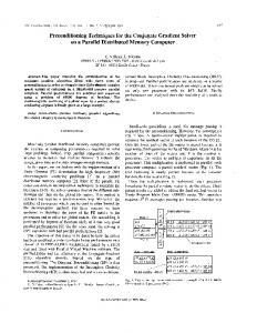
n Figure 1. A void, with respect to destination D, occurs at node S where greedy forwarding fails.
less networks, this problem must be tackled. Although a dense deployment of wireless nodes can reduce the likelihood of the occurrence of a void in the network, it is still possible for some packets to encounter voids that are induced by obstacles, unreliable nodes, the boundaries of a wireless network, and the like. These packets have to be discarded when only a single greedy-forwarding strategy is used, even though a topologically valid path to the destination node may still exist. Thus, it is imperative to design a void-handling technique for geographic routing in an effective and efficient manner. Our contribution in this article is to survey the state of the art of void-handling techniques for geographic routing in wireless networks. We also compare these techniques from different perspectives and discuss directions of future research on this problem. The remainder of the article is structured as follows. We first describe basic concepts of geographic routing and present some general goals for designing a void-handling technique. We then survey void-handling techniques currently available in the literature, followed by a qualitative comparison of these techniques. Finally, we point out some possible directions of future research and conclude the article.
BASIC CONCEPTS AND PROBLEM DESCRIPTION Geographic routing [6] usually consists of two main elements: a location service and a geographic forwarding strategy. The location service is responsible for determining the position of the packet destination, before a packet can be sent from a source node. The position of the packet destination is then carried in the header of the packet so that intermediate hops can learn where the packet is destined for. Geographic forwarding operates in two modes: geographic greedy-forwarding mode and void-handling mode. 3 In the greedy-forwarding mode, selection of a next-hop node for packet forwarding is made according to the positions of the current node, its neighboring nodes, and the destination node. A node can determine its own position either by preconfiguration if the node is stationary, or via a GPS receiver, or through 3 Sometimes
it is called the back up mode or recovery mode in the literature [10, 28].
IEEE Communications Surveys & Tutorials • 1st Quarter 2007
localization algorithms. The positions of the neighboring nodes are accessed either from a centralized neighborhood table at the node [10] or in a distributed fashion via contention among neighboring nodes [29]. The position of the destination is contained in the header of the packet sent by the source node. If any intermediate node happens to know a more accurate position of the destination, it may choose to update the position in the packet header before forwarding the packet. Various greedy-forwarding algorithms [6] differ in the optimization criterion that is applied in the selection of a next-hop node. If a sender needs to forward a data packet and it cannot locate a next-hop node with positive progress toward the packet destination, it switches to the void-handling mode. In this mode, the node attempts to route the packet around the void because it is very likely that a topologically valid path from the source to the destination node exists. For example, as depicted in Fig. 1, there exists a valid path from S to D: S – A – B – C – E – D. However, S is closer to the destination D than any of its neighboring nodes. Thus, it cannot use greedy forwarding to move the packet any further towards D. In this case, the packet is said to have encountered a communications void with respect to the destination D and gets stuck. Node S is called a void node while the shaded region, without any nodes inside, is called a void area. The existence of communications voids is a serious problem and how to handle voids in an effective and efficient manner is an important technical challenge for any viable geographic routing protocol. Due to the unpredictable patterns of node deployment and the uncertain dynamics of timevarying wireless network environments, it is impossible to predict when and where a void will occur. Without an appropriate void-handling technique in place, some data packets may get lost in the network, wasting precious network resources as well as disabling communications between some pairs of nodes in a wireless network. In particular, such network behavior is highly undesirable in mission-critical wireless networks such as sensor networks, because a few failures to detect critical events may defeat the whole mission of sensor network applications. Intuitively, the simplest void-handling technique is flooding, initiated at a void node and executed afterward at all the nodes receiving the stuck packet for the first time. The technique will certainly enable the packet to reach the destination if at least a path exists. However, this technique is effective but inefficient in terms of resource utilization, because every other node in the network has to forward the packet once and the destination node may receive too many unnecessary copies of the same data packet from different paths. In addition, the first copy of the stuck packet arriving at the destination may not follow the optimal path from the void node to the destination. What optimal means depends upon the optimality criterion. For instance, the minimum energy criterion may favor a path with the largest number of hops, while the minimum delay criterion may favor a path with the smallest number of hops (i.e., the shortest path) [8]. An early study in [1] also suggested that the packet should be forwarded to the node with the least negative progress if no next-hop node with a positive progress can be located. However, it is likely to result in the problem of looping of the stuck packet, where this rule forces the packet to oscillate between the void node and the node with the least negative progress. In addition, some studies on geographic routing either proposed not to forward stuck packets at void nodes [2] or circumvented this problem with an assumption of a high node density such as in [30] so that voids are not encountered at all.
51
Thus, some advanced techniques are desireable for handling voids in an effective and efficient manner. Here we present some general goals, which can be applied to the design of a viable void-handling technique for a geographic routing protocol in a targeted wireless network. First, handling a void should involve as few nodes as possible. It would be desirable if voids could be handled at void nodes only. Second, in the absence of data traffic at a void node, it is preferable for a void-handling technique not to incur any overhead. Third, greedy forwarding in geographic routing at most exploits the localized information; it is thus desirable for a void node to exploit as little amount of network information as possible to handle the void. Such a technique will not degrade the inherent scalability of geographic routing. Fourth, the path for the stuck packet to route around a void should not be much worse than the optimal topologically valid path (e.g., the shortest path). Finally, handling voids should be resource efficient, because resources in wireless networks, compared with wired networks, are quite limited.
VOID -HANDLING TECHNIQUES In this section we survey the state of the art of void-handling techniques currently available in the literature. For an indepth understanding of these techniques, we separate these techniques from their relevant geographic routing protocols. That is, we present basic principles and inherent characteristics of these techniques, independent of other components of geographic routing as well as of any wireless network environment with specific network characteristics. Note that a voidhandling technique is invoked only when a data packet encounters a void and greedy forwarding fails at the void node. Once the stuck data packet overcomes the void or reaches a node that is closer to the destination than the void node, greedy forwarding is then reactivated for the packet. We classify the existing void-handling techniques into the following six categories of approaches employed: planargraph-based, geometric, flooding-based, cost-based, heuristic, and hybrid. In the following we discuss each one in detail.
PLANAR-GRAPH-BASED VOID HANDLING Void-handling techniques in this category have attracted a significant amount of research effort and they exploit the properties of planar graphs. The main techniques in this category are some planar graph traversal algorithms such as convex face routing [22], original face routing [9], the face-2 algorithm [12], Other Face Routing (OFR) and Other Adaptive Face Routing (OAFR) in GOAFR [18], and GOAFR+ [19]; some distributed planarization algorithms such as Relative Neighborhood Graph (RNG) [10] and Gabriel Graph (GG) [10]; and some complete void-handling techniques in proposed geographic routing protocols including perimeter routing in Greedy Perimeter Stateless Routing (GPSR) [10], Request-Response (RR) in Beacon-Less Routing (BLR) [28], and bypass in Priority-based Stateless Geo-Routing (PSGR) [33]. Theoretically, it has been shown that a planar-graphbased technique guarantees packet delivery4 [12] because planar graph traversal ensures that a path is discovered if there does exist a topologically valid path.
Basic Principle — In graph theory, a planar graph is a graph that can be embedded in the plane so that no edges intersect. On an embedding of the planar graph, a simple planar graph traversal approach can be used to find a path towards the destination, based on the ancient idea of the right-hand rule, which states that it is possible to traverse every wall in a maze by keeping one’s right hand against the wall while walking forward. In a wireless network, a set of nodes can be considered a unit disk graph in which the nodes are vertices and an edge exists between two vertices if their distance is less than r, where r is the radio range for a wireless node. Here, we assume that all nodes in the network have the uniform radio range of a disk of radius r. Note that the underlying graph formed by a wireless network is usually not planar. Thus, some additional techniques are required to extract a planar subgraph from the original network graph. Otherwise, loops may form in routing paths. It is important to note that the decision as to whether an edge remains in the planar subgraph must be made in a distributed fashion, that is, the decision is made locally by each node. Thus, the performance of a planar-graph-based void-handling technique depends not only on the performance of the planar graph traversal algorithm, but also on the performance of the distributed planarization algorithm. For the former, the main performance concern is the quality of paths discovered by the traversal algorithm, that is, whether the traversed path is optimal such as the shortest path. Two main performance concerns are considered for the latter [22]: one is that a distributed planarization algorithm should be performed in an efficient and effective fashion, while the other is that the quality of topologically optimal paths in the planar subgraph should not be much worse than that in the original network graph. In the following, we review some advances in planar graph traversal algorithms and a few distributed planarization algorithms, as well as the existing planar graph-based voidhandling techniques. Planar Graph Traversal Convex Face Routing: Traversal over a convex planar graph [22] assumes that each vertex knows the circular order of its neighboring vertices and that all faces5 of the graph are convex, except the outer infinite face. Starting from a source vertex, the algorithm walks around the faces of the planar graph, which are progressively closer to the destination vertex. Figure 2 shows how this traversal is carried out. We start in the face of the graph just beyond the source vertex S along the line SD and walk around the face, either clockwise or counterclockwise. Note that once the direction is picked, say counterclockwise, the direction remains fixed during the traversal. The traversal is completed if D is reached. If not, when the line SD is about to be crossed, we cross over into the next face along the line SD. The above process is repeated until D is reached. Original Face Routing: Original face routing [9] works for arbitrary planar graphs. A connected planar graph partitions the plane into faces, not necessarily convex. As shown in Fig. 3, the boundary of each of these faces is bounded by a closed polygon in which we admit some edges of the graph to appear twice. Differently from the rules applied in convex face routing, original face routing traverses each involved face to determine a vertex at which the polygonal bounding edge intersects the line between a source vertex and a destination vertex,
4
Note that the guarantee of packet delivery is ensured only at the topology level, some other factors, e.g., packet collisions at the MAC layer and packet loss due to network congestion, are not considered here.
52
5
Faces are regions bounded by polygons made up of edges of a planar graph.
IEEE Communications Surveys & Tutorials • 1st Quarter 2007
construct an example planar graph for which, when we use the clockwise direction of the right hand rule, the discovered path is much better than the other path when we use the counterD S clockwise direction. An example graph is shown in Fig. 6. Note that curve (1) is the path discovered by the clockwise direction of the right hand rule while curve (2) is the path discovered by the counter-clockwise direction of the rule. Obviously, curve (1) is much shorter than curve (2). In order to find good-quality paths, OAFR was proposed in GOAFR [18] and was later enhanced in GOAFR+ [19]. The basic idea of Figure 2. Traversal over a convex planar graph by walking around faces OAFR is to limit how far away from the line SD counterclockwise. a path is allowed to deviate. For example, if the length of the optimum path is L, then every vertex on the optimum path must lie inside an ellipse with the which maximizes its distance to the source vertex. Then the source vertex and the destination vertex as foci, which defines algorithm continues to traverse and returns to the determined the curve of points whose sum of distances to S and D is L. If vertex, at which time it switches into a new face bordering on the edge. For instance, as shown in Fig. 3 from [9], when the we know L in advance, then we do not allow the path to go algorithm traverses in the face F1, it walks around each edge around the whole face, the algorithm can turn around at a certain vertex and walk around the face using the direction of F 1 and finally switches to the face F 2 from the vertex X opposite to the previously used direction. For instance, an where it has determined the bounding edge XY between F 1 example path discovered by OAFR is shown as curve (3) in and F2 faces. The algorithm repeats until the destination verFig. 6, note that the algorithm turns around at the vertex X. tex D is reached. Curve (3) thus has much better quality than curve (2). Even Face2: The Face2 algorithm [12] and the planar graph when we do not know L a priori, we can easily get around this traversal strategy of perimeter routing in the GPSR protocol [10] are two very similar planar graph traversal techniques. by guessing L [22]. The algorithm can start with a small guess They both employ a traversal algorithm that is similar to conand double it every time it fails to reach D with our current guess, until D is reached. Note that this idea can also be vex face routing, walking along faces of planar graphs and applied to perimeter routing along the same line and this proceeding along the line connecting the source and the destitechnique is called adaptive perimeter routing. In [18, 19], it nation. However, since they have to be applied to arbitrary has been shown that a path discovered in OAFR is efficient planar graphs, as shown in Fig. 4, sometimes the line SD may for practical average-case networks while in theory it is intersect a face more than twice. Face2 needs to determine all asymptotically worst-case optimal. face boundary crossings with SD and selects the one farthest from S. For example, in Fig. 4, when the algorithm traverses to the vertex X, it encounters two face boundary crossings Planarization — In this survey we introduce two popular dis(i.e., the edge XY and the edge XZ), the algorithm then tributed planarization techniques to extract a planar subgraph from the original network graph [10], using only local conselects the edge XY because it is farther from S than the edge XZ. structions. More details about planarization especially spanner Other Face Routing: OFR [18] is a variant of original face properties of planar graph can be located in [11]. The main routing. In OFR, after exploring the complete boundary of a idea of these two techniques is to keep an edge for vertices x face, not necessarily convex, we advance to a vertex on the and y if a geographic region around the edge xy, called the boundary of the face closest to the destination vertex. Then witness region, is free of other vertices. we switch to a new face intersecting the line connecting the In the Relative Neighborhood Graph (RNG) technique, an vertex and the destination. Note that in original face routing, edge is introduced if the intersection of the circles centered at we advance to a vertex at which the bounding edge intersects two nodes is free of other nodes. Figure 7 from [10] illustrates the line between a source vertex and a destination vertex, then the RNG technique. In the Gabriel Graph (GG) technique, it switches into the new face bordering on the edge at the veran edge is introduced if the circle of diameter xy is free of tex. For instance, as shown in Fig. 5, OFR switches at the vertex X from the face F 1 to the face F 4 because the face F4 is closest to the destination vertex D. Instead, original face routing switches at the vertex Y to the face F 2 . Thus, when other face routing is employed, the D traversal walks over faces F 1 , F 4 , Y and F5. Instead, if the original face routing is used, the traversal walks S F1 over faces F1, F2, and F3. F2 Other Adaptive Face Routing: The previously introduced traversal X algorithms cannot ensure that the quality of paths discovered is good in all possible planar graphs. As pointed out in [22], we can easily Figure 3. Planar graph traversal using the original face routing algorithm.
n
n
IEEE Communications Surveys & Tutorials • 1st Quarter 2007
53
request and all neighboring nodes reply with a packet indicating their positions. Then the void node Y extracts a planar subgraph using a Z localized planarization algorithm D such as the GG technique for its neighborhood and forwards the S packet via unicast according to the X well-known right-hand rule. Similarly to perimeter routing in GPSR, the position where greedy forwarding failed is stored in the packet header. As soon as the packet arrives at a node closer to the desFigure 4. Planar traversal using either the face2 algorithm or perimeter routing. tination than the void node, it switches back to greedy forwarding again. Note that the RR technique increases the overall netother nodes. Figure 8 from [10] illustrates the Gabriel Graph work delay, due to its instant request for the information of technique. Note that the GG planar graph is actually a superneighboring nodes. graph of the RNG planar graph. Other distributed planarization techniques include the Bypass: Bypass is the void-handling technique employed in Restricted Delaunay Graph (RDG) [20] and the Localized the PSGR protocol [33]. Similar to the previous planar graph Delaunay Triangulation (LDel) [21]. Note that in [20] it was traversal algorithms, the traversal in bypass employs the wellargued that the RDG planarization extracts better-quality known right hand rule to circumvent a void. Two main differpaths than the RNG planarization and GG planarization techences in bypass exist. One difference is that, in bypass, a node niques both in theory and in practice. moves the stuck packet to another node without exploiting the prior knowledge of network topology or neighboring nodes. That is, a bypass next-hop node is established in a distributed Planar-graph-based Void-Handling Techniques fashion among neighboring nodes instead of in a centralized Perimeter Routing: Perimeter routing, as the complete voidmanner at the sender. The other difference is that the direchandling technique in the GPSR protocol [10], consists of a planar traversal algorithm, a distributed planarization algotion of the right hand rule may be switched between clockwise rithm, as well as some other protocol optimizations. In GPSR, and counter-clockwise during the traversal while the direction a planar subgraph of the original graph is computed during a is fixed in most of the planar traversal algorithms. As shown preprocessing phase using the RNG planarization technique in Fig. 9, bypass separates the whole plane into two sides, by or the GG planarization technique. When a packet gets stuck the line SD connecting the void node S and the destination at a void node in greedy forwarding, perimeter routing is node D. Curve (1) shows that, if the edge XY exists, the stuck enabled and the planar traversal algorithm, similar to the packet gets around the void successfully using the clockwise Face2 routing, is used for the stuck packet to walk around the direction of the right hand rule. If the edge XY is broken, the void. The header of a stuck packet usually carries information stuck packet has to follow curve (2) to cross over the line SD, such as the position of the void node, the position of the last that is, the packet goes into the west side from the east side. intersection that causes a face change, and the first edge traIn this situation, bypass switches the direction of the right versed on the current face. Such information helps each node hand rule from clockwise to counter-clockwise, and the packet make all routing decisions locally. For example, this informathen walks along curve (3). Without changing the direction, tion makes a traversal algorithm terminate appropriately. As the packet has to follow curve (4). The article argued that shown in Fig. 4, if the destination D is not reachable from S, such switch can lead to a routing trajectory that gets around the void from the west side more efficiently. However, the then the packet will loop around an interior or an exterior bypass mechanism implies an assumption that the underlying face of the planar graph. The information about the first edge graph formed in a wireless network must be planar to begin traversed can be used to determine if a packet traverses the first edge on the current face for the second time. Perimeter routing is disabled if a node is encountered that is closer to the destination than the void node. Note that there is no guarantee that perimeter routing will find good-quality paths in the D planar subgraph [22]. Request-Response: RR is the F3 void-handling technique used in the F2 S F1 BLR protocol [28]. In BLR, a comY plete planar subgraph is not conF5 structed for the original network F4 graph but a partial planar subgraph is constructed for nodes around a void node on demand (i.e., only when there is data traffic going through the void node). The void X node, when it needs to forward a stuck packet, first broadcasts a short Figure 5. Planar traversal using other face routing.
n
n
54
IEEE Communications Surveys & Tutorials • 1st Quarter 2007
D
1
3
S
2
X
n Figure 6. An example to demonstrate the quality of discovered paths using different directions of right hand rule.
with. Otherwise, traversal based on the right handle rule cannot function appropriately. The assumption is often invalid in practice, which makes the use of the bypass void-handling scheme somewhat questionable.
GEOMETRIC VOID HANDLING This category exploits the underlying geometric properties of voids by considering some inherent topological structures (i.e., holes), behind the seemingly unorganized nodes. In [13], holes are defined as the regions of the network with boundaries consisting of all the nodes which can possibly become void nodes in greedy forwarding. Thus, when a packet gets stuck at a void node, it must be at the boundary of at least one of the holes. Note that the idea of holes and hole-surrounding paths in this category is mainly used in the context of wireless sensor networks where routing around voids is only one of the possible applications using holes. The seminal work in this category is BOUNDHOLE [13]. When a destination node is outside a bounded hole, BOUNDHOLE guarantees that a stuck packet will always get to the destination. Basic Principle — The main principle behind techniques in this category is to identify holes in a network by making use of the geometric properties of deployed nodes.6 Depending on application requirements, these paths can be found on demand (i.e., only when a packet gets stuck at a void node), or they can be discovered in a preprocessing phase and stored locally along the boundaries of holes. Unlike the planar graph approach, computing and storing the information regarding holes is necessary only for the problematic parts of the network. In order to identify a hole around a void node, a node should first use a rule to detect if it can possibly be a void node. This task is implemented by the TENT rule [13]. As shown in Fig. 10 from [13], for each node p, all its one-hop neighboring nodes are ordered counterclockwise. For each pair of adjacent nodes u and v, the perpendicular bisectors of up and vp intersect at the point O (center of the circle shown). If O is within the communications range of p, the black region must also lie within the range of p. Since u and v are adjacent,
IEEE Communications Surveys & Tutorials • 1st Quarter 2007
there are no nodes inside the black region and p cannot get stuck for any destinations in the direction of upv. Conversely, if O is outside the range, there must be a destination in the plane for which the packet can get stuck at p. After being identified as a void node, node p can initiate the BOUNDHOLE algorithm to bound a hole around it. A hole is a closed region bounded by a non self-intersecting polygonal loop. The basic idea is shown in Fig. 11 from [13]. There are nodes s, p, t1, and t2 bounding a hole. The algorithm starts from p and sweeps over the stuck direction by sending a packet to a neighboring node t1 in a counterclockwise order. Node t1 further passes this packet on to its neighboring nodes bounding the hole, in this case, node t2. The above process is repeated until the packet marks the boundary of the hole and returns to node p after walking over the boundary. Since the boundary of a hole has been cached locally in that region, it provides a conduit for the subsequent stuck packets being routed around the void area in a way similar to that of perimeter routing on a planar graph.
BOUNDHOLE — The following description demonstrates how a geographic routing protocol can exploit hole-surrounding paths discovered by BOUNDHOLE [13] to handle voids. As shown in Fig. 12 from [13], when greedy forwarding is in use, a packet gets stuck at a void node p. According to the BOUNDHOLE algorithm, we know that p must be on the boundary of a hole. The boundary connects the void nodes and possibly some non-void nodes into a cycle bounding an area in a network topology. The void node then routes the packet along the boundary of the hole. When the packet reaches a node closer to the destination q than node p, the packet is greedily forwarded again. Figure 12a shows an exam6
Note that there exist some techniques which identify holes without exploiting any location information of nodes in the literature [14–17]. Since we assume the availability of geographic information in this survey, we do not further discuss such techniques.
W X
Y
n Figure 7. The RNG planarization technique. For edge (x,y) to
be included, the shaded lung area must contain no witness node w.
55
X
W
nodes, a void node remembers the stuck packet ID via an entry in its cache corresponding to a specific destination and refuses to accept the same packet from any of its neighboring nodes. After accepting the stuck packet, every neighboring node of the void node acts independently and exploits greedy forwarding to forward its own copy of the stuck packet. If any of neighboring nodes has to select the void node from which the stuck packet originally came from in its greedy forwarding, the void node, upon the receipt of the packet, initiates a rejection packet back to acknowledge the neighboring node, so that the neighboring node will select the next best node from its own neighboring nodes. If no appropriate node can be selected, the node becomes a new void node. One-hop flooding can again be executed at the new void node and the above process is repeated. Figure 13 shows an example to illustrate how one-hop flooding handles a void. Note that a similar idea can be further extended into an n-hop flooding technique where n is larger than or equal to two. Partial Hop-by-hop Routing: In GRA [25], a packet will be delivered to a destination node by greedy forwarding if no void is encountered. When a packet gets stuck at a void node for a specific destination, it starts route discovery. The routediscovery phase finds a path from the void node to the destination on demand and updates routing tables at all the nodes on the path from the void node toward the destination. After the route discovery is successfully completed, the stuck packet can be routed from the void node to the destination by partial hop-by-hop routing. Flooding, called breadth first search in GRA, is proposed for use in the route discovery phase. The flooding efficiency depends on the duration of communications between the void node and the destination. The longevity of communications allows to amortize the cost of flooding in finding paths, so that the frequency of the occurrence of flooding at void nodes is well controlled. Note that in [24, 25], another class of route discovery technique other than flooding-based techniques, that is, the depth first-search-based technique, is also proposed for route discovery to find good quality paths in an effective and efficient manner. Partial Source Routing: PSR [26] is an on-demand and
Y
n Figure 8. The GG planarization technique. ple where the destination is outside the hole. In this case, such a node which is closer to the destination q than node p must exist (e.g., node u). In fact, if we connect the line pq, it crosses the boundary of the hole at edge uv. Both u and v are closer to q than p itself. Thus, the packet will always get to the destination. Note that BOUNDHOLE tends to impose higher load on nodes near the hole boundaries. Also, in [13] the use of restricted flooding is proposed to handle voids in the case that the destination q lies within the hole, as shown in Fig. 12b, which will be presented in detail subsequently.
FLOODING-BASED VOID HANDLING Void-handling techniques in this category exploit the simplest communications means in a network (i.e., flooding), to get a stuck data packet to get around a void. It includes one-hop flooding [23], Partial Hop-by-hop Routing (PHR) 7 in Geographic Routing Algorithm (GRA) [24], and Partial Source Routing (PSR) in On-demand Geographic Forwarding (OGF) [26]. It is straightforward to show that most of these techniques guarantees packet delivery for connected graphs [23]. Basic Principle: As we know, original flooding, in which every node in the network is supposed to receive a copy of stuck packets, is a simple and effective technique to handle voids. We call original flooding full flooding. However, full flooding is inefficient in terms of resource utilization. Although some efficient full flooding algorithms have been proposed in the literature [27], they still cost too much while handling voids, because only the destination node wishes to receive stuck packets from void nodes. Thus, some advanced flooding-based void-handling techniques are desired to efficiently handle voids. The main goal is to make every effort to control the range of flooding as well as the frequency of occurrence of flooding at void nodes to a desired extent, so that the flooding cost is minimized while effectively handling voids. Such a flooding mechanism is called restricted flooding or partial flooding [45]. One-hop Flooding: One-hop flooding [23] is a kind of restricted flooding and it is used at a void node to broadcast the stuck packet only to its one-hop neighboring nodes instead of flooding to every node in the network as full flooding does. After flooding the packet to all its neighboring 7
This name is called in this survey for our convenience.
56
1 X
S
Y
3 2
4
West side
East side
n Figure 9. Traversal directions in bypass. IEEE Communications Surveys & Tutorials • 1st Quarter 2007
Void-handling techniques in this category exploit a costbased idea to handle voids. This group mainly includes costbased forwarding in Partial-partition Avoiding Geographic Routing-Mobile (PAGER-M) [35] and Distance Upgrading Algorithm (DUA) [36]. It is intuitive that cost-based techniques guarantee packet delivery in connected graphs. Basic Principle — In cost-based void handling, a packet flows from a node with a higher cost to a node with a lower cost [37]. The definition of cost varies between different contexts. When designing a cost-based void-handling technique, each node in the network is first assigned a cost, which may be equal to its Euclidean distance to the destination. A packet is still forwarded greedily until it gets stuck at a void node, then cost-based forwarding is enabled. The void node increases its cost to a value larger than its Euclid distance to the destination, so that the packet can finally be directed by the high-cost-to-low-cost rule along efficient paths to get around the void.
O Black region
v
u p l1
l2
n Figure 10. The TENT rule to detect void nodes. stateless void-handling scheme and it enables a void node to forward any stuck data packet to either a targeted destination node directly or to a node which has a nearer distance to the destination than itself. PSR consists of two phases: partial path discovery and source packet forwarding. In the partial path discovery phase, a void node uses a method similar to expanded ring search [41] to identify a partial path starting from the void node. At first, the void node tries to discover a partial path by flooding a discovery packet within all two-hop neighboring nodes. If the discovery is successful, the phase is complete. If the discovery fails, the void node initiates another discovery to its three-hop neighboring nodes, that is, it extends the flooding range to one more hop than the previous search. The above process is repeated until a targeted node is found or the maximum number of runs for partial path discovery defined by the protocol is reached. In the latter case, the stuck packet is discarded. A study in [42] shows that the majority of voids can be circumvented in four hops or less. In the source packet forwarding phase, the void node knows at least a partial path to the destination or to another better-positioned node if a path exists. The void node includes the source path in the data packet’s header and forwards the packet to the specified next-hop node. All immediate nodes will follow the specified source path and forward the packet over in-between hops. Note that, in PSR, no other nodes except the void node store and maintain any learned paths. An example is shown in Fig. 14 to illustrate how PSR handles a void. Similar to partial hop-by-hop routing, the cost of discovering a partial path by flooding in PSR can be amortized over the relatively long duration of communications.
COST-BASED VOID HANDLING
IEEE Communications Surveys & Tutorials • 1st Quarter 2007
Cost-based Forwarding — Cost-based forwarding in PAGER-M [35] is employed to handle voids. It consists of two phases: the shadow-spread phase and the cost-spread phase. The former is used to identify shadow nodes (i.e., void and potential void nodes) and bright nodes (i.e., nonvoid nodes). Such status information, along with the position information, is exchanged among neighboring nodes by onehop periodic beacons. After this phase, the original network graph is divided into shadow areas with shadow nodes and bright areas with bright nodes, as shown in Fig. 15a. Node A then initiates the cost-spread phase. As Fig. 15b shows, node A finds that all its neighboring nodes have larger costs, A then increases its cost to be larger than the maximum cost of its neighboring nodes by δ (δ is set to 3 here). After this cost is propagated to nodes B and C, nodes B and C find that all their neighboring nodes have larger costs. In response, they also increase their costs to 23 and 25, respectively, as shown in Fig. 15c. This phase ends when A again increases its cost from 22 to 28, as illustrated in Fig. 15d. Now, every shadow node (A, B, and C in this example) has at least a neighboring node with a smaller cost. Figure 15e shows that the void node A can use cost-based forwarding to forward any stuck packets to
Hole
t2 s
t1
p
n Figure 11. Greedy sweeping in BOUNDHOLE. 57
q
u
v
p q u‘
u
v v‘
p (a) The destination q is outside the hole.
(b) The destination q lies within the hole.
n Figure 12. An example to show how a protocol uses a hole-surrounding path. get out of void nodes. Note that cost-based forwarding may not route packets along voids [35]. It tries to route packets originating at other nodes away from void nodes before they get stuck. The article also considered how the technique can adapt to a mobile wireless network [35]. Distance Upgrading Algorithm — DUA, the basic costbased idea similar to cost-based forwarding in PAGER-M, is presented more formally in [36], which also investigated two possible problems caused by such cost-based void-handling idea. The first one is that DUA may produce inefficient routing paths, as shown in Fig. 16b. After distance upgrading, most nodes follow an inefficient path from x, clockwise around the void to reach the destination. The reason is that the cost at node x is upgraded too high. The study proposed a distance downgrading mechanism to bring the cost down to an appropriate level, as shown in Fig. 16c. The second problem is that when a void disappears, the routing graph may need to be modified in order to make use of shorter paths. For example, a newly deployed node may enable some new links around a void node. Routing paths processed by distance upgrading and downgrading algorithms beforehand may remain correct but not optimal in terms of shortest paths. Thus, the distance recovery algorithm proposed in [36] is required to dynamically adjust costs at some nodes, in response to network dynamics, to take advantage of optimal paths available in the network.
HEURISTIC VOID HANDLING Void-handling techniques in this category exploit some heuristics to handle voids. This group includes alternate network [23], active exploration [34], passive participation [29, 31], void avoidance [39], Intermediate Node Forwarding (INF) [38] and Anchored Geodesic Packet Forwarding (AGPF) in terminode routing [40]. Packet delivery is usually not guaranteed. Basic Principle — These techniques are based on some intuitive ideas that are nonamenable to a strict theoretical analysis on their effectiveness and efficiency. The basic principle is either to utilize some extra resources or to directly exploit some inherent properties of network topology and some geo-
58
graphic properties of void areas. Alternate Network — If an alternate network (e.g., a satellite network, etc.), is available for an occasional use, void nodes can exploit such extra network to get stuck packets around voids, using the network as intermediate hops. Note that such a void-handling technique requires each node in the network to be equipped with another alternate wireless networking technique as a backup, which may cost too much. Active Exploration — When a packet encounters a void and gets stuck at a void node, it gradually increases its transmission power, hence increasing transmission range, until a node with a positive progress is located. Such a void-handling technique, called active exploration, was proposed in [34] and was implied in [32]. The technique requires a void node to be equipped with an adjustable power control. In addition, it would increase interference to the neighboring nodes which might degrade the MAC layer network performance. When the power of the void nodes is sufficiently large, finally the void node can communicate with the destination node directly, even though it cannot locate an available next-hop node with a positive progress towards the destination. Passive Participation — The idea of passive participation appears in [29, 31] and it exploits a self-healing property of network topology itself. Once a node identifies itself as a void node, it simply discards the data packet and keeps itself from volunteering to forward any subsequent data packets toward the destination. The node may periodically check if it can locate a neighboring node with a positive progress in order to participate packet forwarding at a later time. This simple strategy has a reverse-propagation effect which eventually informs other intermediate nodes to explore other possible paths in the network, so that those void nodes in some bad zones are avoided on routing paths. A passive participation example is shown in Fig. 17. Node S is sending a packet to node D, and the packet is stuck at node V, which drops the packet and then initiates passive participation. The subsequent packets will automatically be routed to the second bestpositioned node A and they finally reach D via B, C, and E. However, passive participation may not always be effective. For instance, as shown in Fig. 18, source S wants to deliver a
IEEE Communications Surveys & Tutorials • 1st Quarter 2007
A
A
S
S
D
D
B
B
(a) One-hop flooding is executed at the void node S. Nodes A and B receive the stuck packet.
(b) The copy of the stuck packet at node A is delivered back to the destination D by greedy forwarding.
A
A
S
S
D
io ct
B
Re
je
B
n
X
D
C (c) Using greedy forwarding, node B has to send its copy of the stuck packet back to Node S, which then rejects the packet by acknowledging node B with a rejection packet. Node B cannot locate another appropriate node and becomes a new void node.
(d) One-hop flooding is executed at the void node B and greedy forwarding is reactivated again at node C to deliver the copy of the stuck packet back to the destination D.
n Figure 13. An example to demonstrate how one-hop flooding handles a void. sequence of data packets to destination D. The first data packet is greedily forwarded to node V at the first hop. However, node V cannot continue to greedily forward the data packet. Node V drops the data packet and will not participate in forwarding the subsequent data packets for destination D any more. It seems to S that node V does not exist in the topology. However, no other node with a positive progress in its neighborhood can help forward the subsequent data packets. Thus, data packets will have to be discarded although a topologically valid path does exist from S to D: S–V–A–B–C–E–D. It was argued in [34] that passive participation is not effective in a randomly deployed wireless network with a low node density. Void Avoidance — Differently from passive participation, a void node in void avoidance [39] actively sends a packet to its
IEEE Communications Surveys & Tutorials • 1st Quarter 2007
upstream node to signal the existence of a void. As shown in Fig. 19, there is no node to forward packets from node V to node D. That is, node V is a void node. Node V actively sends out a backpressure beacon to signal the upstream node I that node D is not reachable from it. Node I then sets the SendToDelay for node V to infinity and stops sending packets to node V. Instead, Node I reroutes packets to node A. If node A does not exist, further backpressure will occur until a new path is located. It was argued in [39] that it is guaranteed to find a greedy path if one exists, although void avoidance is not guaranteed to find a topologically valid path. Intermediate Node Forwarding — Intermediate node forwarding (INF) [38] is a probabilistic solution for routing around voids via intermediate geographic locations. When a packet is stuck at a void node, the void node discards the pack-
59
B
B C
C E
E
A
A D
V
S
D
V
S
(a) A partial path request packet is initiated at the node V with Time to Live (TTL) is equal to 2, this discovery fails.
(b) Another partial path request packet is initiated with TTL is equal to 3.
B
B C
C E
E
A
A
V
D
S
(c) A partial path reply packet is sent back from node C, which is closer to data sink D.
V
D
S
(d) The stuck data packet is then forwarded to node C by source packet forwarding and a void is resolved. Greedy forwarding is reactivated for the packet at this time.
n Figure 14. An example to demonstrate how PSR handles a void. et and sends a notification to the source node of the packet. The source node of the packet then chooses a single intermediate position randomly for a circle around the midpoint of the line between the source node and the destination node. Packets have to traverse that intermediate position. If the packet is discarded again, the radius of the circle is increased and another random position is chosen. This is repeated until the packets are delivered to the destination or until a predefined value has been reached and the source node assumes that the destination is unreachable. Figure 20 from [38] demonstrates an example of INF. Source A is sending a packet to destination G and their midpoint is m. There exists a topologically valid path: A–B–C–D–E–F–G. The packet initially traverses AB and gets stuck at node C, because C is closer to G than D. C drops the
60
packet and sends an NAK packet back to A. A then initiates INF with a radius of r1, with L1 randomly chosen as the intermediate location. A new copy of the packet traverses AB, and this copy is again dropped at C because C is close enough to L1 to switch the packet out of the INF mode, but still cannot locate a neighboring node closer to G. A has to choose another new intermediate location L2 from the disc with a radius of r2, another new copy of the packet can now pass through C to D, from which the packet is delivered to G via E and F using greedy forwarding. Anchored Geodesic Packet Forwarding — Differently from other void-handling techniques, AGPF in terminode routing [40] is a preventive technique, which tries to prevent a packet
IEEE Communications Surveys & Tutorials • 1st Quarter 2007
20 B
17
20 15
18
17 15
18
B
20
7 A C
A
D C
8
20
7
22
A
D C
8
19
12 23
15
23
7
16
19
B
17
22
D 8
25
12 23
16
(a) Nodes A, B, C are determined as void nodes in the shadow-spread phase.
20 B
20
12 23
16
(b) Node A increases its cost to 22.
17
20 15
23
B
20
(c) Node B and C increase their costs to 23 and 25 respectively.
17 15
23
7 A C
28
7 A
D 8
25
C
28
20
16
(d) Node A increases cost again to 28.
D 8
25
12 23
16
12 23
20
16
(e) Cost gradient is finally set up and any stuck packet can get out of void nodes by cost-based forwarding.
n Figure 15. An example to demonstrate how PAGER-M handles a void using cost-based forwarding. from encountering voids before sending the packet, that is, the technique lowers the probability of the occurrence of a void on the path the packet traverses, while other techniques attempt to detect voids and then handle them. In AGPF, a packet at the sender includes a list of positions of anchors in the packet header, which is used as loose source routing information. The packet must pass by the areas of these anchors on its way to its destination. The packet is forwarded greedily between anchors. If the anchors are correctly set, then the packet will reach the destination with a high probability. Note that the sender needs to acquire the position information of anchors and maintain it periodically. AGPF also suggested to use perimeter routing occasionally when there is a void in terminode distribution between two anchors [40].
HYBRID VOID HANDLING Void-handling techniques in this category combine at least two void-handling techniques together to handle voids more effectively and more efficiently. These techniques may belong to the same category or to different categories. Whether or not a hybrid void-handling technique can guarantee packet delivery depends on specific void-handling techniques combined. Basic Principle — There are two possible situations where a hybrid void-handling technique is needed. One is that a single void-handling technique cannot handle voids effectively for all possible network topologies. For example, in AGPF as introduced in above, its loose source routing technique cannot always prevent a packet from encountering a void in advance. Thus, perimeter routing is also used in cases when a void occurs occasionally. The other is where one technique, when combined with another technique, can enhance the efficiency of handling voids or reduce the required network resources.
IEEE Communications Surveys & Tutorials • 1st Quarter 2007
Next, we demonstrate three hybrid void-handling techniques. Partial Source Routing Plus Passive Participation — In some resource-constrained wireless networks such as sensor networks, passive participation can be incorporated into Partial Source Routing [26] to handle voids more efficiently. For example, if energy reserve at a void node is lower than a threshold value and the node learns from the past, according to the content of data or high-level description, that its own data is more critical than data from other nodes [44], the void node can initiate passive participation to discourage itself from forwarding any data traffic destined for the destination which causes the void. This means that the void node will not forward any data packets for other nodes in favor of sending its own packets. The void node expects that any subsequent data packets at the previous hops automatically follow other possible paths and get around this void node. When a node receives a partial path request packet corresponding to partial source routing, it will not respond with a path reply packet if it is passive for that destination, even though the node is closer to the destination than the void node initiating the partial path request packet. This hybrid void-handling technique can improve resource utilization while ensuring that the critical data traffic can be delivered. BOUNDHOLE Plus Restricted Flooding — BOUNDHOLE [13] cannot handle a void if the destination is inside the hole, because it is possible that all the nodes in the hole are not closer to the destination than the void node is. For example, as shown in Fig. 12b, p is closer to q than all other nodes on the boundary of the hole. q is indeed reachable via nodes v′ and u′. Note that u′ is inside the hole while v′ is outside the hole. However, since u′ is not within the communication range of any node on the boundary of the hole. In this situation, the
61
30
113
35
25
40 20
20 45
X
10
40
D
10
45
X
40
D
35
25
Y 10
45
X
40
D
35 10
30
35 10
30 20
25
(a) The original cost (Euclidian distance to the destination) distribution.
50 20
115
Y
10 20
45
35 111
15
Y
40
112
114
30 20
25
(b) The cost distribution after distance upgrading.
25
(c) The cost distribution after distance downgrading.
n Figure 16. An example to demonstrate how distance downgrade produces efficient routing paths. stuck packet will have to come back to the void node p along the boundary of the hole without being able to locate a node closer to the destination. Restricted flooding, as mentioned above, is initiated to allow each node on the boundary of the hole to broadcast the stuck packet to all its one-hop neighboring nodes. As illustrated in Fig. 12b, node v′ will get the flooded packet and then it can employ greedy forwarding to deliver the packet to the destination q through u′ and other nodes inside the hole. BOUNDHOLE itself cannot guarantee the packet delivery. However, using BOUNDHOLE plus restricted flooding, a packet will always reach the destination.
• Distributed: Does a technique only exploit localized information? • States: What range of states are required to be maintained at a void node? • Complexity: How complex is it for a technique to be implemented and to be executed? • Communications overhead: What amount of communications overheads are required? • Scalability: Is a technique scalable to the number of void nodes in the network?
COMPARISON Active Exploration Plus Passive Participation — This hybrid void handing technique combines the active exploration and the passive participation techniques. It is suitable for a network in which each node has an adjustable power (thus transmission range) but the maximum power is limited. In this scheme, if a node encounters a void, it increases its transmission range gradually until the maximum value. If it still cannot locate a forwarding node during this active exploration, then it switches to the passive participation scheme, discouraging itself from picking up any following data packets for that destination. The advantage of this scheme is that it attempts to overcome the weakness of passive participation in areas of low node density by increasing the transmission range up to a certain limit. This scheme requires a limited node transmission range only and is thus superior to a single voidhandling technique of active exploration in this regard.
Table 1 presents our comparison. Some observations are summarized in the following. Note that each void-handling technique has its advantages as well as its disadvantages. Selecting an existing technique or designing a new void-handling technique depends on the desirable features of a geographic routing protocol as well as on the unique characteristics of a targeted wireless network and its applications. Guaranteed Delivery — From the table, we can observe that planar-graph-based, flooding-based, and cost-based void-han-
B c
QUALITATIVE COMPARISONS In this section we compare the main void-handling techniques discussed previously in a qualitative manner. Key aspects of this comparison are the effectiveness and the efficiency of handling voids. First, we describe some criteria which are used in this comparison and then we present our comparison.
E
A
D
S V
CRITERIA The following criteria are used in this qualitative evaluation. • Guaranteed delivery: Can a technique, in theory, guarantee that a stuck packet is delivered to its destination if a topologically valid path does exist? • Path quality: Is the path traversed by a stuck packet optimal (e.g., the shortest path)? • Reactive: Does a technique handle voids on demand (i.e., is void handling initiated only when a packet gets stuck at a void node)?
62
n Figure 17. An example on passive participation. IEEE Communications Surveys & Tutorials • 1st Quarter 2007
B
tive or proactive.
c
E A
D V
Distributed — Since greedy forwarding in most geographic routing protocols is a localized algorithm (i.e., it at most exploits information from one-hop neighboring nodes), it is desirable that a void-handling technique is also a localized algorithm. Fortunately, several currently available techniques are localized. However, PHR, PSR, INF, AGPF, and PSR plus passive are not localized, because they have to interact with some nodes other than one-hop neighboring nodes.
S
n Figure 18. An example void where passive participation fails. dling techniques guarantee that a stuck packet can be delivered if at least a topologically valid path exists from a void node to the packet destination. BOUNDHOLE can have a guaranteed delivery if the destination of a stuck packet is outside a void. Otherwise, it needs to be combined with restricted flooding to ensure packet delivery. If an alternate network exists, a stuck packet can get around a void using that network. Although other techniques are probabilistic solutions and they cannot guarantee delivery, some of them may have other advantages such as simplicity and efficient resource utilization. Path Quality — For most planar-graph-based void-handling techniques other than AOFR, not much can be said about the quality of paths. We can easily construct an example where, when the stuck packet goes around the faces clockwise, the quality of the path traversed is far better than that of the path by going around the faces counterclockwise. The quality of paths in AOFR has been shown to be asymptotically optimal in [18]. PHP and PSR can also discover an optimal path if they use an optimality criterion such as the shortest path in their routing selection. DUA can dynamically adjust its cost distribution at nodes so that an optimal path is discovered. For the rest of the techniques, they can discover one of the possible paths, but if more than two paths exist, they cannot make sure that an optimal path is always discovered. Reactive — Proactive techniques incur more overhead while reactive (i.e., on demand) techniques introduce an additional delay for handling voids. From the table, most planar-graphbased techniques, excluding request-response and bypass, are proactive, requiring nodes to construct a planar subgraph periodically. Note that the planar graphs are actually not used most of the time. Most of the packets reach their destinations by greedy forwarding only [10]. Thus, keeping a planar graph at every node all the time is very costly. Cost-based techniques also require a preprocessing to propagate appropriate costs around voids. A sender in AGPF needs to acquire some positions of anchors for every packet destination in advance. Most of other void-handling techniques are reactive, that is, void handling is initiated only when a packet gets stuck at a void node. Not that a void-handling technique based on BOUNDHOLE can be designed to be either reac-
IEEE Communications Surveys & Tutorials • 1st Quarter 2007
States — The fewer states that are required to be maintained, the better performance a void-handling technique can achieve in a large-scale and highly dynamic wireless network. All planar-graph-based, geometric, cost-based void-handling techniques are stateless, that is, they only maintain the states of neighboring nodes. PHR, PSR, and PSR plus passive participation need to maintain states with a partial path from a void node to a packet destination. AGPF needs to update the states of anchors periodically. Interestingly, some techniques such as flooding, one-hop flooding, passive participation, void avoidance, and active exploration are state free, that is, they do not maintain global and even local states. Complexity — Complexity indicates how difficult it is for a technique to be implemented, if it requires an extra resource, and how complex its protocol processing is. BOUNDHOLE has a high complexity due to its complex protocol, as do PHR, PSR, and AGPF. Alternate network and active exploration require some extra resources and thus they have high complexity. All hybrid handling techniques are complex, because at least one of their components has high complexity. Most of other void-handling techniques are of medium complexity. Flooding, one-hop flooding, passive participation, and void avoidance are very simple and have low complexity. Communications Overhead — Communications overhead evaluates how many messages are required to be transmitted when handling a void. Face routing has a high overhead because it has to traverse all edges of a face before it enters a new face. In addition, most planar-graph-based techniques require periodic one-hop beacons, which incurs
B C A
E
D S
I
V Back pressure
n Figure 19. An example on void avoidance. 63
r2 A
lations. The results would be able to reveal, under a specified wireless network with unique characteristics, which technique is most suitable for handling voids for geographic routing.
B
r1
NOVEL VOID-HANDLING APPROACHES
m C
L1 G
D
L2 F E
n Figure 20. An INF example. a lot of communications overhead, to construct a planar subgraph. Flooding-based techniques require a large amount of communications overhead due to the nature of flooding. However, note that such overhead can be amortized if a discovered path is exploited for a long-lived communications session. Bypass, passive participation, and active exploration all have a low overhead because their void-handling mechanisms do not require many communications among nodes. Scalability — Most localized void-handling techniques are scalable to the number of void nodes. Exceptions are flooding and one-hop flooding; network performance plummets with an increasing number of void nodes, due to too many flooding packets. Instead, some global techniques, such as PHR, PSR, and INF, are not scalable, either because too many flooding packets are used in discovering partial paths or because too many notification packets are required at void nodes to signal source nodes to restart geographic greedy forwarding. The rest of the void-handling techniques are scalable, which means that the network performance does not deteriorate quickly when these techniques are used to handle a large number of voids in a wireless network.
DIRECTIONS OF FUTURE RESEARCH In the survey it has been shown that there are quite a number of techniques using different approaches for handling voids. However, there still exist some interesting problems that need to be addressed in the future research.
QUANTITATIVE COMPARISON While we have provided a qualitative comparison of the currently available techniques, it is of great importance to compare them quantitatively. To the best of our knowledge, some of these techniques have been studied theoretically at the topology level, while other techniques have been studied implicitly in evaluating the performance of their respective geographic routing protocols by network-level simulations. Note that these studies are limited either to an individual void-handling technique or to a category of void-handling techniques using the same approach. So far, we have not seen any research study dedicated to the evaluation of at least some of them from different categories together on a quantitative level. Further, some appropriate performance metrics need to be defined for evaluating void handling. The quantitative studies may be done analytically or by network-level simu-
64
As we have presented in this survey, six different void-handling approaches — planar-graph-based, geometric, floodingbased, cost-based, heuristic, and hybrid — have been proposed to handle voids. Each void-handling approach has its strengths as well as its limitations. It would be interesting to know if there exist any other void-handling approaches. If so, what are the characteristics of new void-handling approaches, when compared to the existing approaches?
PROBLEMS IN PLANAR-GRAPH-BASED TECHNIQUES In the past study of planar-graph-based techniques, we usually assume that routing takes place much faster than network dynamic change such as node movement, thus a network can be viewed as a static network at the routing layer. While planar-graph-based techniques using the right hand rule are quite mature for static networks, it would be more interesting to gain a better understanding of how these techniques behave when the topology of the network frequently changes. Furthermore, it is important to figure out a reasonable network model for highly dynamic networks, under which these techniques can be further studied. As pointed out in [38], planar-graph-based techniques such as perimeter routing make unrealistic assumptions about radio ranges and neighboring information, the behavior of these techniques should be investigated if these assumptions are violated, for example, if there are obstructions to radio signals in a network. Some fundamental problems in planar-graph-based techniques include if there exists any better distributed planarization algorithm than those introduced previously, in terms of the quality of paths when compared to the topologically optimal paths in the original graph, and if a void-handling technique is able to find these good quality paths, provided that the paths remain in the planar subgraph. Also, as using planarization may disconnect a connected network with particular patterns of obstacles between nodes, such impact on the performance of geographic routing protocols should be carefully evaluated.
CHARACTERIZING HOLES In BOUNDHOLE, holes are discovered in advance for the future use of routing to avoid holes. However, in order to record the discovered path, it requires much greater resources such as memory storage compared to planar graph traversal, especially when holes have a very large boundary. It would be very interesting to know more inherent characteristics of holes under wireless networks of different sizes or node densities, each with an ad hoc deployment of nodes. Such characteristics include distribution of holes in the network, sizes of holes, and so forth. Some preliminary work has been presented in [42]. After an in-depth understanding of the characteristics of holes, a more efficient void-handling technique than BOUNDHOLE can be designed by exploiting such knowledge a priori.
MINIMIZING FLOODING EXPENSE A key aspect of a viable flooding-based void-handling technique is to minimize the flooding cost. Thus, more efficient
IEEE Communications Surveys & Tutorials • 1st Quarter 2007
Technique
Guar. Del.
Optimal Path
Reactive
Distributed
States
Complexity
Overhead
Scalability
Face
Yes
No
Proactive
localized
state-less
medium
high
Yes
OFR
Yes
No
Proactive
localized
state-less
medium
medium
Yes
Perimeter
Yes
No
Proactive
localized
state-less
medium
medium
Yes
AOFR
Yes
Yes
Proactive
localized
state-less
medium
medium
Yes
RR
Yes
No
Reactive
localized
state-less
medium
medium
Yes
Bypass
Yes
No
Reactive
localized
state-less
medium
low
Yes
BOUNDHOLE
sometimes
No
either
localized
state-less
high
medium
Yes
Flooding
Yes
No
Reactive
localized
state-free
low
high
No
One-hop Fl.
Yes
No
Reactive
localized
state-free
low
high
No
PHR
Yes
Yes
Reactive
global
partial-pathstate
high
high
No
PSR
Yes
Yes
Reactive
global
partial-pathstate
high
high
No
Cost-based
Yes
No
Proactive
localized
state-less
medium
medium
Yes
DUA
Yes
Yes
Proactive
localized
state-less
medium
medium
Yes
Alternate
Yes
No
Reactive
localized
state-free
high
medium
Yes
Active
No
No
Reactive
localized
state-free
high
low
Yes
Passive
No
No
Reactive
localized
state-free
low
low
Yes
Avoidance
No
No
Reactive
localized
state-free
low
medium
Yes
INF
No
No
Reactive
global
state-less
medium
high
No
AGPF
No
No
Proactive
global
partial-pathstate
high
medium
Yes
PSR+Passive
No
No
Reactive
global
partial-pathstate
high
high
No
B.H.+Flooding
Yes
No
either
localized
state-less
high
high
No
Active+Passive
No
No
Reactive
localized
state-free
high
low
Yes
n Table 1. Characteristics of void handling techniques. strategies for restricting the flooding range and rate while still being able to circumvent voids are needed. Furthermore, it is possible to develop some efficient methods other than flooding in the route discovery phase of PHR and PSR.
PERFORMANCE OF COST-BASED VOID HANDLING The performance of cost-based void-handling techniques depends on the number of destinations, the number of void nodes, and network dynamics. The currently available costbased void-handling techniques can handle a moderate number of void nodes with a limited number of destination nodes under a relatively static wireless network. Otherwise, network
IEEE Communications Surveys & Tutorials • 1st Quarter 2007
performance will get worse due to too much overhead incurred by cost adjustment and maintenance around void regions. Cost-based void-handling techniques fit into the context of most wireless sensor networks very well, where the number of data sinks are usually limited and routing usually occurs much faster than topology changes. It would be desirable to develop some advanced optimization strategies to reduce the overhead of cost adjustment and maintenance.
FORMAL ANALYSIS FOR HEURISTIC VOID HANDLING Some formal theoretical analyses are required to explain when and where some heuristic techniques are applicable. For
65
instance, although we learn, from simulations, that passive participation does not function well in a relatively low-density wireless network, we do not have a strict analysis to understand the phenomenon as well as the relation between node density and the effectiveness of passive participation. Similar analyses are also desired for active exploration, void avoidance, INF, and AGPF. These results may be derived in the probabilistic sense.
OTHER PROBLEMS It is desirable to design more hybrid void-handling techniques if such combinations can enhance the effectiveness of handling voids or can reduce the required resources in void handling. Also, strategies in order to prevent a very long detour of a stuck packet are desired for the existing void-handling techniques to be efficient in practical average-case network topologies. Further, most existing void-handling techniques are designed with some unrealistic assumptions such as equal node transmission ranges, unidirectional links, precise location information, and the like. It would be interesting to see how these techniques perform, either theoretically or by networklevel simulations, under some more realistic assumptions. Finally, as far as we know, all current techniques have considered voids in a two-dimensional coordinate system. Whether these void-handling techniques are still feasible in a threedimensional coordinate system needs more in-depth research work. Handling three-dimensional communications voids in a realistic environment would be very interesting and challenging.
CONCLUDING REMARKS In this survey article we have reported on the state of the art of void-handling techniques for geographic routing in wireless networks. We have discussed some general goals for designing a viable void-handling technique and have classified the currently available techniques into six different categories of different handing approaches. For each category, we described its basic principle and surveyed almost all existing void-handling techniques each in some detail. These techniques were then compared in a qualitative manner, using eight criteria from different perspectives. Finally, some interesting and challenging research problems in this area were identified in order to stimulate more creative research in the future.
REFERENCES
[1] H. Takagi and L. Kleinrock, “Optimal Transmission Ranges for Randomly Distributed Packet Radio Terminals,” IEEE Trans. Commun., vol. 32, no. 3, 1984, pp. 246–57. [2] T. Hou and V. Li, “Transmission Range Control in Multihop Packet Radio Networks,” IEEE Trans. Commun., vol. 34, no. 1, Jan. 1986, pp. 38–44. [3] P. Misra and P. Enge, Global Positioning System: Signals, Measurements, and Performance, Massachusetts: Ganga–Jamuna Press, 2001. [4] A. Savvides, C. Han, and M. B. Strivastava, “Dynamic Finegrained Localization in Ad-Hoc Networks of Sensors,” Proc. ACM MobiCom 2001, Rome, Italy, July 2001. [5] N. Bulusu, J. Heidemann, and D. Estrin, “GPS-less Low Cost Outdoor Localization For Very Small Devices,” IEEE Pers. Commun. Mag., vol. 7, no. 5, Oct. 2000, pp. 28–34. [6] M. Mauve, J. Widmer, and H. Hartenstein, “A Survey on Position-based Routing in Mobile Ad Hoc Networks,” IEEE Network Mag., vol. 15, no. 6, Nov. 2001, pp. 30–39. [7] J. C. Navas and T. Imielinski, “Geographic Addressing and Routing,” Proc. ACM MobiCom 1997, Sept. 1997. [8] P. Gupta and P. R. Kumar, “The Capacity of Wireless Net-
66
works,” IEEE Trans. Info. Theory, vol. 46, no. 2, 2000, pp. 388–404. [9] E. Kranakis, H. Singh, and J. Urrutia, “Compass Routing on Geometric Networks,” Proc. 11th Canadian Conf. Computational Geometry, Vancouver, Canada, August, 1999. [10] B. Karp and H. T. Kung, “Greedy Perimeter Stateless Routing for Wireless Networks,” Proc. ACM MobiCom 2000, Boston, MA, Aug. 2000. [11] X.-Y. Li, “Topology Control in Wireless Ad Hoc Networks,” chapter in Mobile Ad Hoc Networking, IEEE Press, 2004. [12] P. Bose et al., “Routing with Guaranteed Delivery in Ad Hoc Wireless Networks,” Wireless Networks, vol. 7, no. 6, 2001, pp. 609–16. [13] Q. Fang, J. Gao, and L. J. Guibas, “Locating and Bypassing Routing Holes in Sensor Networks,” Proc. IEEE INFOCOM 2004, Hong Kong, Mar. 2004. [14] S. P. Fekete et al., “Neighborhood-based Topology Recognition in Sensor Networks,” Proc. ALGOSENSORS 2004, Turku, Finland, July 2004. [15] S. Funke, “Topological Hole Detection in Wireless Sensor Networks and its Applications,” Proc. ACM DIALM-POMC 2005, Cologne, Germany, Sept. 2005. [16] A. Kröller et al., “Deterministic Boundary Recognition and Topology Extraction For Large Sensor Networks,” Proc. ACM SODA 2006, Miami, Florida, 2006. [17] Y. Wang, J. Gao, and J. S.B. Mitchell, “Boundary Recognition in Sensor Networks by Topological Methods,” Proc. ACM Mobicom 2006, Los Angeles, CA, 2006. [18] F. Kuhn, R. Wattenhofer, and A. Zollinger, “Worst-case Optimal and Average-case Efficient Geometric Ad-hoc Routing,” Proc. ACM MobiHoc 2003, Annapolis, MD, June 2003. [19] F. Kuhn et al., “Geometric Ad-hoc Routing: of Theory and Practice,” Proc. ACM PODC 2003, 2003. [20] J. Gao et al., “Geometric Spanners for Routing in Mobile Networks,” Proc. ACM MobiHoc 2001, 2001, pp. 45–55. [21] X-Y. Li, G. Calinescu, and P-J. Wan, “Distributed Construction of Planar Spanner and Routing for Ad Hoc Wireless Networks,” Proc. IEEE INFOCOM 2002, 2002, pp. 1268–77. [22] F. Zhao and L. J. Guibas, Wireless Sensor Networks: An Information Processing Approach, Morgan Kaufmann Publishers, July 2004. [23] I. Stojmenovic and X. Lin, “Loop-Free Hybrid SinglePath/Flooding Routing Algorithms with Guaranteed Delivery for Wireless Networks,” IEEE Trans. Parallel and Distributed Systems, vol. 12, no. 10, Oct. 2001. [24] R. Jain, A. Puri, and R. Sengupta, “Geographical Routing Using Partial Information for Wireless Ad Hoc Networks,” IEEE Pers. Commun., Feb. 2001, pp. 48–57. [25] I. Stojmenvoic, M. Russell, and B. Vukojevic, “Depth First Search and Location Based Localized Routing and QoS Routing in Wireless Networks,” Computers and Informatics, vol. 21, no. 2, 2002, pp. 149–65. [26] D. Chen and P. K. Varshney, “On Demand Geographic Forwarding for Data Delivery in Wireless Sensor Networks,” Elsevier Computer Commun. J., special issue on Network Coverage and Routing Schemes for Wireless Sensor Networks, 2006. [27] S. Ni et al., “The Broadcast Storm Problem in a Mobile Ad Hoc Network,” Proc. ACM MobiCom 1999, Seattle, Washington, Aug. 1999. [28] M. Heissenbüttel et al., “BLR: Beacon-Less Routing Algorithm for Mobile Ad-Hoc Networks,” Elsevier Computer Commun. J., vol. 27, no. 11, July 2004. [29] M. Zorzi and R. R. Rao, “Geographic Random Forwarding (GeRaF) for Ad Hoc and Sensor Networks: Multihop Performance,” IEEE Trans. Mobile Computing, vol. 2, no. 4, Oct.–Dec. 2003. [30] B. M. Blum et al., “IGF: A Robust State-Free Communication Protocol for Sensor Networks,” Technical report CS-2003-11, CS Department, University of Virginia, 2003. [31] D. Chen, J. Deng, and P. K. Varshney, “A State-Free Data Delivery Protocol for Wireless Sensor Networks,” Proc. IEEE WCNC 2005, New Orleans, LA, Mar. 2005. [32] D. Ferrara et al., “MACRO: An Integrated MAC/Routing Protocol for Geographic Forwarding in Wireless Sensor Networks,” Proc. IEEE INFOCOM 2005, Miami, LA, Mar. 2005.
IEEE Communications Surveys & Tutorials • 1st Quarter 2007
[33] Y. Xu et al., “PSGR: Priority-based Stateless Geo-Routing in Wireless Sensor Networks,” Proc. IEEE MASS 2005, Washington D.C., November, 2005. [34] D. Chen, J. Deng, and P. K. Varshney, “On the Forwarding Area of Contention-Based Geographic Forwarding for Ad Hoc and Sensor Networks,” Proc. IEEE SECON 2005, Santa Clara, CA, Sept. 2005. [35] L. Zou, M. Lu, and Z. Xiong, “PAGER-M: A Novel Locationbased Routing Protocol for Mobile Sensor Networks,” Proc. Broadwise 2004, San Jose, CA, Oct. 2004. [36] S. Chen, G. Fan, and J. Cui, “Avoid ‘Void’ in Geographic Routing for Data Aggregation in Sensor Networks,” Int’l. J. Ad Hoc and Ubiquitous Computing (IJAHUC), special issue on Wireless Sensor Networks, vol. 2, no. 1, 2006. [37] F. Ye, A. Chen, S. Lu, L. Zhang, “A Scalable Solution to Minimum Cost Forwarding in Large Sensor Networks,” Proc. IEEE ICCCN 2001, 2001. [38] D. S. J. De Couto and R. Morris, “Location Proxies and Intermediate Node Forwarding for Practical Geographic Forwarding,” Technical report MIT-LCS-TR-824, MIT Laboratory for Computer Science, June 2001. [39] T. He et al., “SPEED: A Stateless Protocol for Real-time Communication in Sensor Networks,” Proc. Int’l. Conf. Distributed Computing Systems, Providence, RI, May 2003. [40] L. Blazevic, S. Giordano, and J. Y. Le Boudec, “Self Organized Terminode Routing,” J. Cluster Computing, vol. 5, no. 2, Apr. 2002. [41] C. E. Perkins and E. M. Royer, “The Ad Hoc On-Demand Distance Vector Protocol,” C. E. Perkins (Ed.), Ad Hoc Networking, Boston: Addison-Wesley, 2000, pp. 173–219. [42] M. Fayed and H. T. Mouftah, “Characterizing the Impact of Routing Holes on Geographic Routing,” Proc. IEEE ICW 2005, Montreal, Canada, Aug. 2005. [43] A. Rao et al., “Geographic Routing without Location Information,” Proc. ACM Mobicom 2003, San Diego, CA, Sept. 2003.
IEEE Communications Surveys & Tutorials • 1st Quarter 2007
[44] S. Bhatnagar, B. Deb, and B. Nath, “Information Assurance in Sensor Networks,” Proc. WSNA 2003, San Diego, Sept. 2003. [45] H. Frey, “Scalable Geographic Routing Algorithms for Wireless Ad Hoc Networks,” IEEE Network Mag., July/Aug. 2004, pp. 18–22.
BIOGRAPHIES
DAZHI CHEN (
[email protected]) is currently a Ph.D. candidate in the Department of Electrical Engineering and Computer Science at Syracuse University. He received B.E. degree and M.E. degrees, from Nanjing University of Posts and Telecommunications, in 1998 and 2001, respectively. His research interests are in wireless networking, mobile computing, and network security. His current research focuses on the design and evaluation of network protocols and algorithms for next-generation wireless multi-hop networks. He is a member of the IEEE and the ACM. PRAMOD K. VARSHNEY (
[email protected]) received a B.S. degree in electrical engineering and computer science (with highest honors) and M.S. and Ph.D. degrees in electrical engineering from the University of Illinois at Urbana-Champaign in 1972, 1974, and 1976, respectively. Since 1976 he has been with Syracuse University, where he is currently a professor of electrical engineering and computer science and the research director of the New York State Center for Advanced Technology in Computer Applications and Software Engineering. His current research interests are in distributed sensor networks and data fusion, detection and estimation theory, wireless communications, image processing, radar signal processing and remote sensing. He is a Fellow of the IEEE and has received numerous awards. He serves as a distinguished lecturer for the IEEE Aerospace and Electronic Systems Society. He was the 2001 president of International Society of Information Fusion.
67